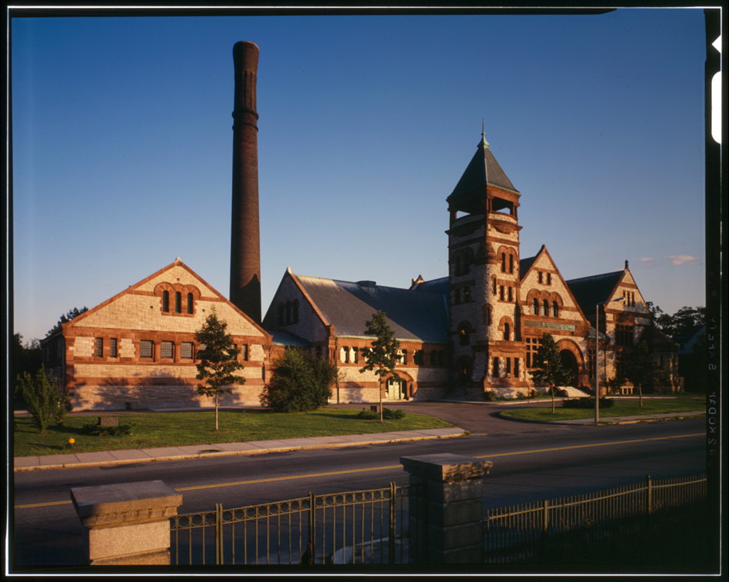
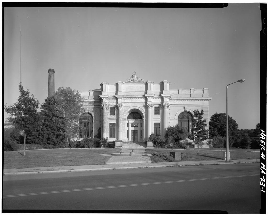
Boston Water Works, Leavitt Pumping Engine, 2450 Beacon Street, Boston
Boston Water Works, Leavitt Pumping Engine, 2450 Beacon Street, Boston, Suffolk County, MA. Surveyed as HAER MASS,13-BOST,75A-, with 1 photograph and a 1,953-word written history.
From the record
“Designed by Erasmus Darwin Leavitt, this machine is an unusual triple-expansion, three-crank rocker engine, high-capacity unit which provided outstanding performance for the Boston Water Works Corporation.”
Written record, HAER MASS,13-BOST,75A- survey. Machine-read text.
surveyed by the federal HAER program as HAER MASS,13-BOST,75A- · the record runs 1953 words · one of 264 surveyed structures published for this county.
Source document
Quoted word for word from HAER MASS,13-BOST,75A-.
Not written, edited or summarised by this site.
Designed by Erasmus Darwin Leavitt, this machine is an unusual triple-expansion, three-crank rocker engine, high-capacity unit which provided outstanding performance for the Boston Water Works Corporation. In it was installed in a high-service pumping facility on the south side of the Chestnut Hill Reservoir in Brighton. This engine was designated an Engineering Landmark in December of by the American Society of Mechanical Engineers. Authors: Historical data taken from American Society of Mechanical Engineers' Landmark dedication ceremony pamphlet prepared by: James J. Matera, P.E., Metropolitan District Commission of Massachusetts, Robert F. Metcalf, P.E., Stone & Webster Engineering Corporation Chestnut Hill, Leavitt Engine HAER No.
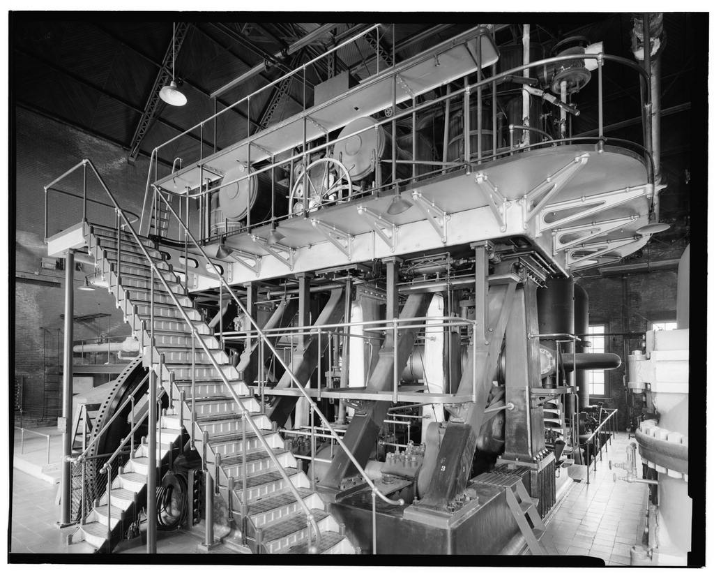
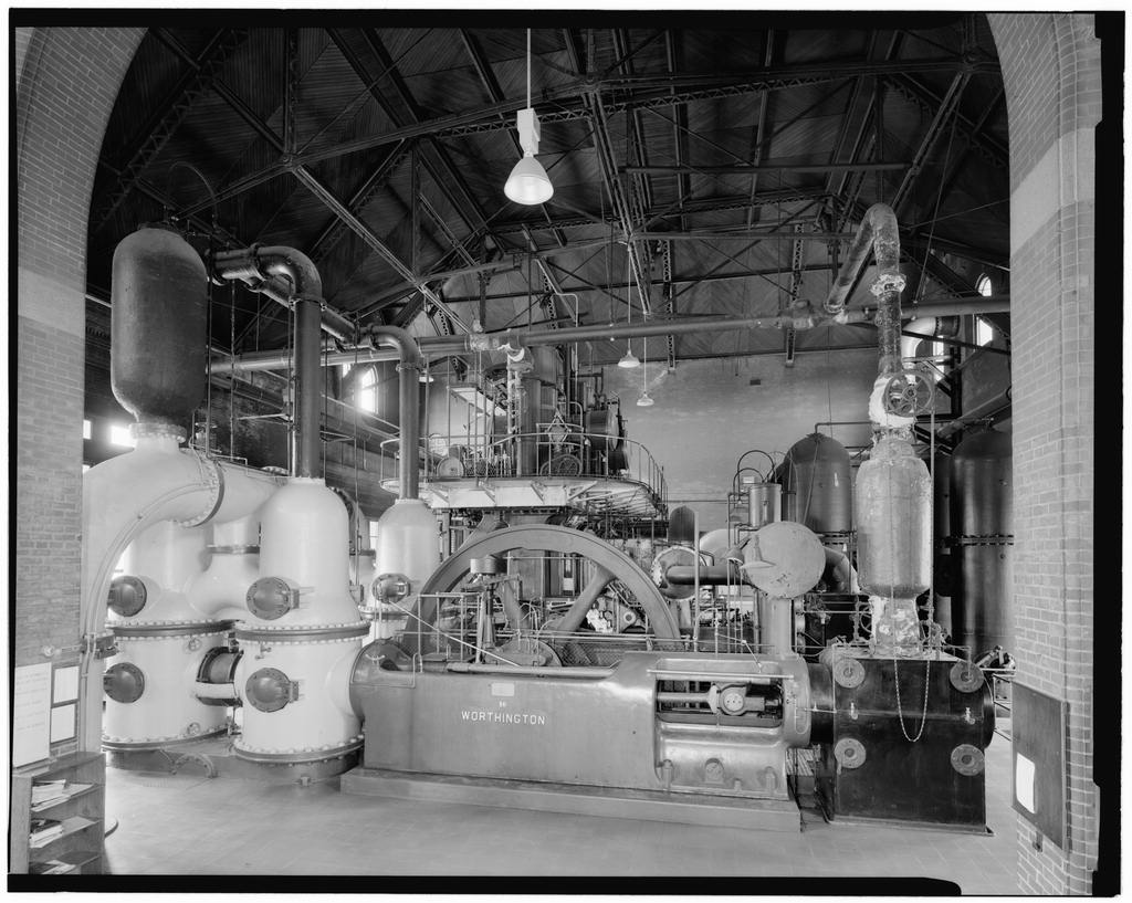
MA-24A (page 2) The Leavitt Pumping Engine was installed in as Engine No. 3 of the Chestnut Hill Station to provide added capacity to the existing pumping units in order to meet the increased demand in the high service areas of Boston. This engine was of unusual design and its performance attracted much attention in the field of steam engineering and municipal water systems. This triple expansion, three-crank rocker engine has three cylinders with diameters of and by a 6-foot stroke. The cylinders are vertical and inverted, and are carried, together with the valve gear, on an entablature supported by six vertical and diagonal columns rising from the bed plate. The engine connecting rods act upon rockers somewhat like bell-cranks, carried in pedestals on the bed plate.
From each rocker, two additional connecting rods run, one to the shaft of the flywheel, this rod being nearly horizontal when the crank is at its highest point. The other connecting rod runs in the other direction at an angle of about 30 degrees, from the horizontal to the plunger rod of the pump proper. The leverage of the various pins in the beams is such that the stroke of six feet, in the case of the steam pistons, is reduced to four feet for the pump plungers, which is also the amount of the double throw of the cranks. The crankshaft has three cranks set at angles of 120 degrees, the low pressure crank leading, followed by the intermediate and high pressure cranks. The shaft is carried on four adjustable four-box pedestals with overhung end cranks.
Between two of these pedestals is the flywheel, and between the other two, the gear for driving the camshaft. The steam and exhaust valves of the engines are gridiron slides worked by cams on a horizontal shaft, which is driven by gearing from the crankshaft. The cut-off of the high pressure cylinder is regulated by the governor through the agency of a hydraulic cylinder, which advances or retards the cut-off cam by means of a spiral sleeve; the cut-offs of the other cylinders are fixed. Steam enters the high pressure cylinder through a separator forming a part of the inlet pipe. After expanding in this cylinder, it passes through a tubular reheater to the intermediate cylinder, and thence through another similar reheater to the low pressure cylinder.
The reheaters have steam of boiler pressure, or about 185 psi, on the inside of the tubes and the working steam on the outside. All the cylinders are steam-jacketed on head and barrels, the low pressure cylinder at 100 psi and the other two at 185 psi. Drains from high pressure jackets and reheaters are returned to the boiler and low pressure jacket drains and water removed from the steam by the separators are discharged to the hotwell. There are three double-acting inclined pump plungers, each of four-foot stroke and inches in diameter. The pump foundation is below the floor of the engine room, the pump chambers being tied to the engine bedplates by horizontal girders, as well as by the pump crosshead guides, which are inclined 30 degrees to the horizontal.
This peculiar arrangement of inclined pumps was found necessary to suit existing conditions of the engine house, pumpwell, etc. By reduction of stroke from that of the engine, as well as by the relation of diameters, an increased capacity for pressure is obtained. -tfe Chestnut Hill, Leavitt Engine HAER No. MA-24A (page 3) The pump bases or suction chambers, six in number, one for each end of each pump, are connected together and the bases of each pump are connected by a separate suction pipe. The lower or working pump chambers are surrounded by annular spaces throughout their height, forming vaccuum chambers. The upper pump chambers contain the delivery nozzles, and above these are the air chambers, all six of the latter being connected by pipes.
The pump valve mechanism, somewhat similar to the valve rod system of a Corliss engine, is one of the characteristic features of the engine, based on the invention of Professor Riedler of the Royal Polytechnic School of Berlin, Germany. This engine was designed to run easily at 60 revolutions per minute, pumping against a head of 128 feet, a speed made possible only by the use of the Riedler valve gear, introduced to the United States in the design of this machine (actually, another Leavitt-Reidler engine began operation a year earlier). At the normal speed of 50 revolutions per minute, the pumping capacity is gallons in 24 hours. The pump valves consist of a number of rigidly connected rings, each closing an annular opening in the valve seat.
The upper valves are delivery valves and the lower are suction valves. The diagonal rods running from the center cam, Corliss engine fashion, and moved by the connecting rods leading from the main rockers, operate to close each valve positively at the exact moment of the reversal of the stroke. As soon as the valves are closed, the mechanism moves out of the way, leaving the valves free to open automatically. This feature makes possible the high velocity. Water is taken from the air chambers to the force main by a horizontal pipe branching into them, also to the square foot surface condenser, where the pumped water passes through the tubes and condenses the engine exhaust steam. After passing through the condenser, the water is delivered to the force main.
Directly below the condenser is the air pump with a 24-inch diameter cylinder and 12-inch stroke, worked by an arm from one of the rocker shafts operating the pump valve gear. Steam for the engine was furnished by a Belpaire fire-box boiler with two separate furnaces and a common combustion chamber. This boiler, no longer in existence, was 34 feet, 4 inches long, with a minimal internal shell diameter of 90 inches. The boiler tubes were 201 in number, 3 inches in diameter and 16 feet long. A Green economizer heated the feed water by flue gases before the water entered the boiler. In a large group of engineering students, under the direction of Professor Edward F.
Miller of the Massachusetts Institute of Technology, conducted a detailed performance test on the engine, principal results of which are tabulated below: Duration, hours .. 24 Total expansion 21 Revolutions per minute Steam-pressure above atmosphere, pounds per square inch '* * Chestnut Hill, Leavitt Engine HAER No. MA-24A (page 4) Barometer, pounds per square inch ..
Vaccuum in condenser, inches of mercury Pressure in high and intermediate jacket and reheaters, pounds per square inch Pressure in low-pressure jacket, pounds per square inch Horsepower Steam per horsepower per hour, pounds Thermal units per horsepower per minute Thermal efficiency of engine, per cent Efficiency for non-conducting engine, per cent Ratio of efficiencies, per cent 74 Coal per horsepower per hour, pounds Duty (foot-pounds per 000 B.T.U.) Efficiency of mechanism, per cent Although most of the engine, including the principal castings, was produced in the United States, Leavitt believed that forgings produced by the Krupp works in Germany were the best obtainable.
In keeping with his high standards, he specified Krupp forgings in the Chestnut Hill pumping engine, and that name appears on several critical parts. The workmanship shown in these components was a point of interest to visiting engineers and students. The nameplate of the engine bears these words, "Boston Water Works, Riedler Pumping Engine, Designed by E. D. Leavitt, Built by N. F. Palmer Jr. & Co., Quintard Iron Works, New York." The engine is still in its original location, retired in though kept in operating condition for some years thereafter. BIOGRAPHICAL
Sketch of the Designer
Erasmus Darwin Leavitt, was born in Lowell, Massachusetts, on October 27, After early education in the Lowell public schools, he served a three-year apprenticeship in the machine shop of the Lowell Manufacturing Company. Following a year's employment with the firm of Corliss and Nightingale, Providence, Rhode Island, he became assistant foreman at the City Point Works (South Boston) of Harrison Loring, where he had charge of construction of the engine of the U.S.S. Hartford. From to Leavitt was Chief Draftsman for Thurston, Gardner & Co., steam engine builders of Providence, Rhode Island, leaving to enter the U.S. Navy at the start of the Civil War. In he was made instructor in Steam Engineering at the U.S. Naval Academy, Annapolis, Maryland.
In Leavitt resigned to resume private practice as a Mechanical Engineer, specializing in pumping and mining machinery. Sixteen patents were issued to him between and in this field. A pumping engine of his design, installed at Massachusetts, and tested in brought him into prominence in the engineering world. He became well acquainted with leading engineers of several European countries, including Professor Riedler of the Royal Polytechnic School, Berlin, Germany, from whom he acquired the right to use the Riedler pump and valve gear in the - ! Chestnut Hill, Leavitt Engine HAER No. MA-24A (page 5) United States.
One of his best known and most successful designs including the Riedler features was that of the twenty million gallon per day pumping engine, installed at Chestnut Hill in and operated for over thirty years by the Boston Water Works and the Metropolitan District Commission. In addition to serving as a consultant for cities and pump and engine builders, Leavitt was mechanical engineering consultant for the Calumet and Hecla Mining Company from to during which time his reputation and fame in the field of mechanical engineering were further recognized as having done more than any other American engineer to establish sound principles and propriety of design.
Leavitt was granted an honorary degree of Doctor of Engineering from Stevens Institute of Technology in the first recipient of this degree from the Institute. Prominent in many engineering societies in this country and England, Leavitt was an original member of the American Society of Mechanical Engineers and its president in He was also a Fellow in the American Academy of Arts and Sciences. He served on the Boston and Cambridge Bridge Commission, the Visiting Committee of the Engineering Department of Harvard University and of the observatory, and was greatly interested in the Cambridge Young Men's Christian Association. Leavitt died on March 11, at Cambridge, Massachusetts, where he had lived for many years.
References
Fitzgerald, Desmond, A Short Description of the Boston Water Works, Boston. Peabody, Cecil H., Thermodynamics of the Steam Engine. 6th edition, Michigan Institute of Technology. The Technology Quarterly, Vol. IX, Massachusetts Institute of Technology Archives. ^
The original filed report, and the sheets the survey produced. Those published here appear above.
Also surveyed in Brighton
4 records
The federal surveyors worked through Brighton building by building. These are the other structures
they measured and filed a report on, longest report first.
 Block
Block