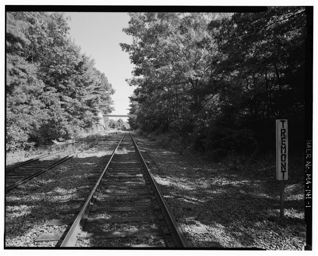
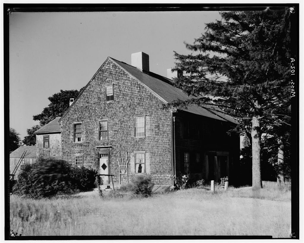
This documentation was initiated as an emergency mitigation measure during the Federally-funded rehabilitation of the Tremont Station Bridge by the Massachusetts Highway Department. During its dismantling for rehabilitation, the bridge was discovered to be far more seriously deteriorated than had been anticipated. This documentation has been prepared to mitigate the effect of the unexpectedly extensive repair work now required. This documentation was prepared between August and August by: Lola Bennett, Historian McGinley Hart & Associates Architects and Planners 77 North Washington Street Boston, Massachusetts Martin Stupich, Photographer 25 Mayhew Street Dorchester, Massachusetts
Boston-Provincetown Bridge No. (Pierceville Road Bridge) HAERNo.MA-141 (Page 2) Site Description The Tremont Station Bridge1 (now more commonly known as Pierceville Road Bridge) is located in the northwest corner of Wareham, Massachusetts in the village of West Wareham, historically known as Tremont. The bridge carries Pierceville Road over the tracks of the former Old Colony Railroad (later used by the New York, New Haven & Hartford Railroad; presently used by Conrail). The surrounding area is wooded and occupied primarily by mid- late twentieth century suburban tract houses, with a scattering of nineteenth century houses.
The segment of Pierceville Road on which the bridge is located is less than one-quarter mile northwest of the former site of Tremont Station, and links Main Street on the north to Pierceville Road, Paper Mill Road and Route 58 on the south. The approaches to the bridge are steep and drop off sharply on either side, as they were built to eliminate a grade crossing at this site. Bridge Description The Tremont Station Bridge is a single-span structure comprised of a pair of pin-connected, wrought-iron Pratt pony trusses measuring long (center-to-center of bearing pins), 0" wide (center-to-center of trusses) and high (center-to-center of upper and lower chord pins). Prior to being disassembled, the bridge rested on granite masonry, straight-wing abutments with stepped wingwalls.
The clear span between the abutments is and the distance from the tracks to the floorbeams was Each six-panel truss is comprised of a built-up upper chord and an eyebar lower chord, connected by vertical and diagonal members. The upper chord of each truss is comprised of two channels connected with a plate on the upper side and lacing and tie plates underneath. The inclined endposts are built up in the same manner. The bottom of each inclined endpost is riveted to a plate with curved ends. These curved plates appear to have been designed as the upper plates of four roller bearing assemblies.
Although Massachusetts Highway Department inspection reports mention roller bearings as late as no rollers or other bearing assembly elements could be locaTed on site in September of The bottom chord is comprised of pairs of 6"x upset-ended eyebars in the outer panels and double pairs of upset-ended eyebars in the two center panels. The members are connected at each upper panel point with a diameter pin fastened with a diameter nut, except at the hip verticals which are connected with a diameter pin fastened with a diameter nut. The members are connected at each lower chord point, including the bearing points, with a diameter pin fastened with a 6 Ml" diameter nut.
All of the upset-ended eyebar heads gain in thickness over the body of the bar and are thickest over 1 This name has been inferred from the earliest documentation found in Old Colony Railroad records and town reports. Since the bridge was apparently moved at an early date, an official "historic" name for the structure could not be documented with absolute certainty. The bridge is located at the site historically referred to as Tremont Station, and has been located here since early in its history. The next earliest citation making reference to the bridge appears to be a record plan of the structure, entitled & Boston to Provincetown Bridge No.
Wareham Road." While this was the official designation of the bridge when it was under the railroad's purview, the bridge has been more commonly referred to by the station name or the modern {Pierceville Road) street name. TREMONT STATION BRIDGE Boston-Provincetown Bridge No. (Pierceville Road Bridge) HAERNo.MA-141 (Page 3) the pin. The upper and lower chords are connected by means of hip verticals (loop-welded eyebars) and vertical posts (paired channels laced back-to-back). Diagonals angling up toward the ends are comprised of paired upset-ended eyebars. Diagonal counters (square rods with turnbuckles and loop-welded eyes) pass between the pairs of diagonal eyebars in the two center panels.
The floor system as originally built consisted of built-up transverse floor beams, comprised of a web plate top and bottom flange plates which are doubled over the central portion of each beam, and flange angles The floor beams were hung from the verticals by U-bolts which looped over the pin at each lower panel point. The U- bolts passed through the flanges of the floor beams, and were secured underneath with a plate and two nuts. The floor beams extended beyond the trusses to support outrigger sway braces, comprised of 3 T-bars, which braced the upper chords of the trusses at each panel point. Timber stringers ran perpendicular to the floor beams and rested on shelf angles (originally riveted to the webs of the floor beams.
The floor beams were rebuilt in at which time the lower lateral system (1" diameter rods) was removed to make room for new shelf angles which were riveted to the webs of the floor beams.2 The floor beams still have anchor brackets for the lower lateral rods. In the stringers and timber plank deck were replaced with new stringers, timbers and 2" thick bituminous concrete pavement. There is a founder's mark: "Union Iron Mill, Pittsburgh, PA," on the upper chord, and a small iron plaque bearing what appears to be the number "7" on the southeast endpost. A town water main also spans the tracks between the abutments, and is presently supported on a steel beam.
When the bridge was in place, the water main rested between the lower chord and the sway braces on the east truss, and was supported on the outer ends of the extended portions of the floor beams. Local History Early in Wareham's history, a number of iron foundries were established when an abundance of iron ore was discovered in the ponds and marshes that surround the town. One such enterprise was the Washington Iron Works, established in by Colonel Bartlett Murdock and George Howland in what is now West Wareham. "This was a large rolling mill and nail factory containing thirty-five machines.
A year later they erected a second dam and built a forge for making bar iron out of scrap iron by a rolling process."3 In Washington Iron Works was purchased by the Tremont Iron Company, whose foundry was located in Wareham center. The company enlarged their works by constructing a second stone dam at Tremont and building "a large storehouse for nails... east of the branch track of the Cape Cod Branch Railroad Company, at Tremont, [as well as] a number of tenements."4 Thus, a 2 See & Boston to Provincetown Bridge No. Wareham Road, Repairs, December, Massachusetts Highway Department, Bridge Section files. 3 Frederika A. Burrows, "Nail-Making in Wareham," Cannonballs and Cranberries (Taunton, MA, p. 38.
4 Noble Warren Everett, "History of Wareham," in History of Plymouth County Massachusetts. Duane Hamilton Hurd, compiler (Philadelphia, p. TREMONT STATION BRIDGE Boston-Provincetown Bridge No. (Pierceville Road Bridge) HAERNo.MA-141 (Page 4) small village was established and became known as Tremont. In the Tremont Iron Company sold its entire assets to the Tremont Nail Company which gained a national reputation for manufacturing cut nails. The West Wareham plant was out of service by the late but the main plant in Wareham Village continues to this day and is reputed to be the country's oldest nail manufacturer. Railroad History In the Cape Cod Branch Railroad received a charter to construct a railroad line from Middleboro to Sandwich on Cape Cod.
This line was completed in and ran through West Wareham and Wareham Village. The following year, the Fairhaven Branch Railroad was chartered to construct a line southward from the Cape Cod Branch Railroad at West Wareham to the town of Fairhaven. This line was completed in Tremont Station was located just east of the junction of these two lines, appearing on historic maps as early as although it was possibly built much earlier. In the two railroad lines became part of the Old Colony Railroad system, a network which at its peak in encompassed over 600 miles of track in eastern Massachusetts.
The Old Colony Railroad was leased by the New York, New Haven & Hartford Railroad in After World War I, passenger service declined and all service was terminated on the Old Colony lines in Conrail presently uses the tracks as a spur line through West Wareham for local freight deliveries on an intermittent basis. Construction of Tremont Station Bridge Early in Pierce of Rochester (the town adjoining Wareham to the west) petitioned the Plymouth County Commissioners for a grade separation at the point where Carver Road crossed the Old Colony Railroad tracks at Tremont Station, and for the alteration of highways over land of the Tremont Nail Company.
A hearing was held at Tremont Station on May 4, as indicated in the annual town report of which states: The railroad company desired that the Carver road should be discontinued at the existing crossing, and that far north of the crossing a highway bridge should be erected twenty feet above the tracks, and new roads be constructed on each side of the railroad to connect this bridge with the existing highways.6 Local citizens expressed concern about "circuitous travel and much new road making," while the Tremont Nail Company was concerned for its lands and tenements, "especially because communication with the mill, and between its two villages would be daily impeded by elevated and winding roads." The town selectmen were largely interested in financial matters, as "the total expenditure was to be considerable-estimated by some computations to aggregate 5 Louis P.
Hager and A.D. Handy, History of the Old Colony Railroad from to the Present Time (Boston, p. 6 Town of Wareham, Selectmen's Apical Report on the Finances of the Town of Wareham for the Year Ending Feb. 1. (Middleboro, MA, TREMONT STATION BRIDGE Boston-Provincetown Bridge No. (Pierceville Road Bridge) HAERNo.MA-141 (Page 5) $15,000-and likely to fall largely upon Wareham."1 Further meetings were held with town and county officials to hear the concerns of all parties. Finally, on November 15, The County Commissioners located the railroad bridge about 500 feet northerly from the Carver crossing, laying out at each end a rising embankment about 200 feet in length for approaches.
They also laid out a new highway easterly from the railroad from the Carver road to the old Middleboro road, connecting with the easterly end of the embankment, or approach, of the bridge. They also laid out a highway from the westerly embankment, or approach, near the Union Chapel, leading southerly through the woodland to the Pierceville road.
And they discontinued the Carver road at the level railroad crossing, and also discontinued the old Middleboro road from the Union Chapel northerly to the house owned by Savary Morse, including another level railroad crossing.^ Special Commissioners appointed by the Superior Court decreed that the bridge, its abutments and embankments were to be built and maintained by the railroad; the roads and highways were to be built and maintained by the town; and the county was to pay all the land damages.9 After advertising for bids, the town selectmen chose local contractor Charles McDermott to build the required roads and approaches.
Town reports indicate that McDermott was paid for this work and that the bridge and abutments were completed in the fall of Whether or not the railroad recycled a bridge from another location is unclear. However, records of the New York, New Haven & Hartford Railroad, the subsequent owners of the structure, indicate that this bridge was originally built in and was rebuilt at its present location just nine years later, in Old Colony Railroad reports from the late nineteenth century indicate that beginning in the the railroad made every effort to eliminate as many grade crossings as possible on its lines. A company report from stated: The work of abolishing grade-crossings has been continued.
Two grade- crossings at Tremont have been avoided by the construction of a new highway in Wareham, partly paid for by this company, and arrangements have been made by which two other highways in Wareham, now crossing at grade, shall be brought together and carried over the railroad by a bridge. ... It is the purpose of the directors wherever a grade crossing of any kind can be abolished, at a reasonable expenditure, to use every effort to remove it.11 7 Ibid., pp. 8 Ibid., p. 8. 9 Ibid., p. 9. 1Q New York, New Haven & Hartford Railroad Bridge List, Massachusetts Highway Department, Bridge Section files. 11 Old Colony Railroad. Twentv-fourth Annual Report of the Directors of the Old Colony Railroad Company to the Stockholders. November (Boston, p. 6.
TREMONT STATION BRIDGE Boston-Provincetown Bridge No. (Pierceville Road Bridge) HAERNo.MA-141 (Page 6) Structural evidence, including missing and/or non-matching rivets at all upper chord splice plates, suggests that the trusses may have been disassembled and moved at an early date. In addition, the heavy proportions of the truss members suggest that the bridge was originally designed to carry railroad loadings, not the much lighter highway loadings of the period.
It has been theorized that the bridge was built in as a railroad bridge at some other location and the trusses were moved and re-erected at their present location in Wareham in The conversion of the bridge from a railroad span to a highway span was possibly prompted by the collapse of the Bussey Bridge in Dedham on March 14, This catastrophe caused many railroad companies to reconsider the adequacy of their metal truss roadway bridges, and to begin replacing those whose adequacy was at all questionable.12 Thomas Pratt and the Pratt Truss The Tremont Station Bridge is a Pratt truss, a common type of short-span bridge at the tum- of-the-century.
Historian Carl Condit has called Thomas Pratt "the creator of...the first scientifically designed truss, [and]...tfte most thoroughly educated American bridge builder at the beginning of the railroad age "u Born in to Boston architect Caleb Pratt, Thomas Pratt was educated early in the field of building construction. He studied architecture at Rensselaer Polytechnic Institute, and went on to work for the United States Army Corps of Engineers. In he began his career designing bridges for railroads and was employed as a structural engineer by a number of New England railroad companies.
In Thomas Pratt and his father Caleb jointly patented the Pratt truss which featured diagonal members in tension and vertical members in compression, thus reversing the truss system patented by William Howe in "The design was superior to Howe's mainly in the more functional distribution of tensile and compressive stresses in the various members."14 The Pratt truss was not particularly popular in the early years for timber bridge construction, but by the standard Pratt truss "was becoming a common feature on the Pennsylvania Railroad and its numerous affiliates. "15 By the turn of the century, the Pratt truss became one of the most common bridge truss types for shorter spans, as noted by J.A.L. Waddell in The Pratt truss...
is the type most commonly used in America for spans under two hundred and fifty feet in length. Its advantages are simplicity, economy of metal, and suitability for connecting to the floor and lateral systems.16 12 Stephen J. Roper, Massachusetts Highway Department Historic Bridge Specialist, "Massachusetts Historic Bridge Inventory: Bridge Pierceville Road Bridge, 13 Carl W. Condit, "Pratt and Whipple Trusses," American Building Art, the Nineteenth Century (New York, p. 14 Ibid., p. 15 Ibid. 16 J.A.L. Waddell, Bridge Engineering, vol. I (New York, p. TREMONT STATION BRIDGE Boston-Provincetown Bridge No. (Pierceville Road Bridge) HAERNo.MA-141 (Page 7) Jacob H.
Linville, Andrew Carnegie and Keystone Bridge Company The Tremont Station Bridge is one of the earliest known examples in Massachusetts of an iron truss incorporating the "weldless," or upset-ended, eyebar patented by Jacob H. Linville and John L. Piper (dates unknown). Linville was a civil engineer who had been employed as chief bridge engineer for the Pennsylvania Railroad and pioneered the use of wide, upset-ended eyebars for tension members. Piper was chief mechanic for the Pennsylvania Railroad shops at Altoona, Pennsylvania. Both men had professional dealings with industrialist Andrew Carnegie who served as Superintendent of the Western Division of the Pennsylvania Railroad Company from until In Jacob H. Linville and John L. Piper received U.S. Patent No.
for an "Improvement in Iron Truss-Bridges," which in part consisted of the use of a series of wide, thin eyebars connected by pins for the lower chord. Three years later, in the two men received a second patent, No. which made certain improvements upon their first patent, including the use of wide, thin eyebars with enlarged ends, formed by upsetting the iron by compression "for the purpose of increasing the density, toughness, and strength of the eye of the rod, and enlarging the eye without diminishing its transverse section."11 The specifications for the lower chord of the bridge truss described within the patent read as follows: The lower chords...
consist of wide, thin rolled iron bars, with enlarged ends, which are made by upsetting the rolled bars by compressing them into the desired shape in molds, into which the heated iron is forced under immense pressure, thereby increasing the density, toughness, and strength of the enlarged ends, and permitting the holes or eyes for the connecting pins... to be cut out without rendering the transverse section at the eye less than that of the other parts of the bar or diminishing the transverse or longitudinal strength of the chord-bar.1* In Linville and Piper, along with Andrew Carnegie and Aaron Shiffler (a bridge supervisor for the Pennsylvania Railroad) were organizing Piper & Shiffler, the predecessor of the Keystone Bridge Company, in Pittsburgh, Pennsylvania.
In his autobiography, Carnegie wrote of the company's formation: When at Altoona I had seen in the Pennsylvania Railroad Company's works the first small bridge built of iron. It proved a success. I saw that it would never do to depend further upon wooden bridges for permanent railway structures. An important bridge on the Pennsylvania Railroad had recently burned and the traffic had been obstructed for eight days. Iron was the thing. I proposed to [sic] Linville, who had designed the iron bridge, and to John L. Piper and his partner, Mr. Schiffler [sic], who had charge of bridges on the Pennsylvania line, that they should come to Pittsburgh and I would organize a company to build iron bridges. It was the first company of its kind. I asked my friend Mr.
[Thomas] Scott, [Vice-President] of the Pennsylvania Railroad, to go with us in the venture, which he did. Each of us paid for a one fifth interest, 17 Jacob H. Linville and John L. Piper, "U.S. Patent No. p. 3. 18 Ibid. TREMONT STATION BRIDGE Boston-Provincetown Bridge No. (Pierceville Road Bridge) HAERNo.MA-141 (Page 8) or My share I borrowed from the bank. Looking back at it now the sum seemed very small but "tall oaks from little acorns grow." In this way was organized in the firm of Piper and Schijfler [sic] which was merged into the Keystone Bridge Company in 1863-a name which I remember I was proud of having thought of as being most appropriate for a bridge-building concern in the State of Pennsylvania, the Keystone State.
From this beginning iron bridges came generally into use in America, indeed, in the world at large so far as I know. ... In Linville, Piper, and Schijfler [sic], we had the best talent of the day- Linville an engineer, Piper a hustling, active mechanic, and Schiffler [sic] sure and steady.19 In anticipating the growing demand for iron railway bridges, Carnegie began to reorganize Piper & Shiftier as the Keystone Bridge Company, a move that was completed by Linville served as President and Chief Engineer, Piper served as General Manager, and Shiftier was Assistant General Manager of the new company.
Keystone Bridge Company initiated the use of wrought iron for all principal truss members and advertised as its specialties: "Linville & Piper Patent Wrought Iron Bridges for Railways, Highways, Parks, Cities & c. Improved Wrought Iron Turn-Tables, Iron Roofs, Patent Tubular Columns and Weldless Eye Bars.,flx These weldless eyebars were also referred to in advertisements as "Upset Chord Links" and were said to be available in any length up to 50 feet and any head width up to 20 inches.22 The company soon obtained many large contracts for railroad bridges, including a 300-foot span over the Ohio River at Steubenville and the Eads Bridge at St. Louis.
By the company had enlarged its works to include: "machine shops, smith-shops, riveting-sheds, bolt-cutting and testing houses, pattern-shops, a large iron building for a foundry, offices, stables, and all the accessories of a first-class establishment. "23 A promotional booklet from enumerated 275 iron truss spans, 110 iron girder spans, and 343 wooden spans, totaling feet in length, which Keystone Bridge Company had constructed for railroads.24 In the demand for all shapes and sizes of iron for bridges led to the erection of a large iron foundry adjacent to the Keystone Bridge shops. Carnegie wrote of this enterprise: !9 Andrew Carnegie. Autobiography of Andrew Carnegie fBoston / New York. pp. 20 Joseph Frazier Wall, Andrew Carnegie (New York, p. 21 Illustration in Victor C.
Darnell, A Directory of American Bridge-Building Companies Society for Industrial Archeology, Occasional Publication No. 4 (Washington, DC, p. 68. 22 Keystone Bridge Company, Illustrated Album. p. 45. 23 Ibid., p. 7. 24 Ibid., pp. TREMONT STATION BRIDGE Boston-Provincetown Bridge No. (Pierceville Road Bridge) HAERNo.MA-141 (Page 9) The Keystone Works have always been my pet as being the parent of all the other works. But they had not been long in existence before the advantage of wrought- over cast-iron became manifest. Accordingly, to insure uniform quality, and also to make certain shapes which were not then to be obtained, we determined to embark in the manufacture of iron.15 Originally known as Carnegie, Kloman & Co., the firm was later known as the Union Iron Mills.
By the ironworks contained: " thirty-seven puddling furnaces, fourteen heating furnaces, seven trains of three-high rolls, and one 'Universal Plate Mill,'" the latter of which was designed and patented by Andrew Kloman for rolling heavy flat bars up to 36 inches in width.26 The immense capacity and success of this company is evidenced by a statement made by J.A. L. Waddell in the introduction to his work The Designing of Ordinary Iron Highway Bridges: "The sections of iron employed [throughout this book] are those rolled at the Union Iron Mills, for the reason that...
[there is] more iron rolled in these mills than anywhere else in America."21 Carnegie continued to invest his profits in his companies and stated in his autobiography that by the mid-1880s Union Iron Mills had become, "the leading mills in the United States for all sorts of structural shapes,"2* A Union Iron Mills founder's mark is visible on the upper chord of the west truss of the Tremont Station Bridge. The Keystone Bridge Company's contribution to the field of engineering technology was undeniably their extensive use of wrought iron for all principal truss members in bridges.
The company was also successful in incorporating many of Linville and Piper's design innovations into their bridges, particularly the use of upset-ended eyebars for lower chords, a feature which would become standard in late-nineteenth century pin-connected trusses. From its inception, the company was an important and prolific late-nineteenth century bridge manufacturer, of which it was said: "In the completeness, extent and adaptation of all the tools and appointments required for heavy bridge construction, these works are unrivalled in this country.,r29 In later years, Carnegie himself wrote of the Keystone Bridge Company's success: The Keystone Bridge Works have always been a source of satisfaction to me.
Almost every concern that had undertaken to erect iron bridges in America had failed. Many of the structures themselves had fallen and some of the worst railway disasters in America had been caused in that way. Some of the bridges had given way under wind pressure but nothing has ever happened to a Keystone bridge, and some of them have stood where the wind was not tempered. There has been no luck about it. We used only the best material and enough of it, making our own iron and later our own steel. We were our own severest inspectors, and would build a safe structure or none at all. When asked to build a bridge which we knew to be of insufficient strength or of 25 Ibid., p. 26 Edwards, p. 27 Ibid. 28 Carnegie, p.
29 Manufactories and Manufacturers of Pennsylvania of the Nineteenth Century (Philadelphia, p. TREMONT STATION BRIDGE Boston-Provincetown Bridge No. (Pierceville Road Bridge) HAERNo.MA-141 (Page 10) unscientific design, we resolutely declined. Any piece of work bearing the stamp of the Keystone Bridge Works (and there are few States in the Union where such are not to be found) we were prepared to underwrite.30 Between and the Keystone Bridge Company became a subsidiary of Carnegie Steel Company and changed its name to Keystone Bridge Works.
In the Keystone Bridge Works was absorbed by Morgan's American Bridge Company, along with 24 other firms representing "fifty percent of the nation's fabricating capacity."31 One year later, American Bridge Company became a subsidiary of United States Steel. At the present time, there are only two other known Keystone-built bridges in Massachusetts: a single-span plate girder highway bridge in Montague and one span of a former three-span Whipple through truss railroad bridge between Montague and Deerfield, both of which were built in for the Turners Falls Branch of the New Haven & Northampton Railroad. Keystone-built bridges were not particularly common in Massachusetts, where many local firms competed for business. 30 Carnegie, p. 31 Darnell, pp.
I TREMONT STATION BRIDGE Boston-Provincetown Bridge No. (Pierceville Road Bridge) HAERNo.MA-141 (Page 11) Sources of Information A. Engineering Drawings New York, New Haven & Hartford Railroad. Boston to Provincetown Bridge No. Record Plan. [Massachusetts Highway Department, Bridge Section files.] B. Historic Views "Bridge No. East Elevation," July [Massachusetts Highway Department, Bridge Section files.] "Bridge No. Field Photos," October [Massachusetts Highway Department, Cultural Resources Section files.] C. Bibliography American Society of Civil Engineers. "Linville, Jacob Hays," biographical sketch in A Biographical Dictionary of American Civil Engineers. ASCE Historical Publication No. 2. New York: American Society of Civil Engineers, Atlas of Surveys.
Plymouth County, and Town of Cohasset. Richards Co., Boiler, Alfred P. Practical Treatise on the Construction of Iron Highway Bridges. 4th edition. New York: John Wiley & Sons, Carnegie, Andrew. Autobiography of Andrew Carnegie. New York: Houghton Mifflin Co., Condit, Carl W. American Building Art, the Nineteenth Century. New York: Oxford University Press, Cooper, Theodore. "American Railroad Bridges," Transactions of the American Society of Civil Engineers, vol. 21, pp. Edwards, Richard, ed. Industries of Pittsburgh: Trade Commerce and Manufactures- Historical and Descriptive Review. Pittsburgh, Everett, Noble Warren. "History of Wareham," in History of Plymouth County Massachusetts. Duane Hamilton Hurd, compiler. Philadelphia: Lewis & Co., Hager, Louis P. and A.D. Handy.
History of the Old Colony Railroad from to the Present Time. Boston: Hager and Handy, Harlow, Alvin F. Andrew Carnegie. New York: Julian Messner, TREMONT STATION BRIDGE Boston-Provincetown Bridge No. (Pierceville Road Bridge) HAERNo.MA-141 (Page 12) Karr, Ronald Dale. The Rail Lines of Southern New England. A Handbook of Railroad History. New England Rail Heritage Series. Pepperell, Mass.: Branch Line Press, Keystone Bridge Company. The Keystone Bridge Company's Illustrated Album. Pittsburgh, Linville, and Piper. "U.S. Patent No. Improvement in Iron Truss-Bridges, January U.S. Patent Office Records, microfilm copies at Boston Public Library. Linville, and Piper. "U.S. Patent No. Improvement in Wrought-Iron Bridges, October U.S.
Patent Office Records, microfilm copies at Boston Public Library. Livesay, Harold C. Andrew Carnegie and the Rise of Big Business. Boston: Little, Brown & Co., Lovell, Daisy Washburn. Glimpses of Earlv Wareham. Wareham Historical Society, The Manufactories and Manufacturers of Pennsylvania of the Nineteenth Century. Philadelphia: Galaxy Publishing Company, Massachusetts Board of Railroad Commissioners. Special Report... in Relation to the Disaster on Monday. March on the Dedham Branch of the Boston & Providence Railroad. Boston: Wright & Potter Printing Co., Massachusetts Highway Department, Bridge Section. Records. Nason, Elias. A Gazetteer of the State of Massachusetts, revised and enlarged by George J. Varney. Boston: Russell, New York, New Haven & Hartford Railroad Bridge Lists.
Massachusetts Highway Department, Bridge Section Records. Old Colony Railroad. Annual Reports of the Directors of the Old Colony Railroad Company to the Stockholders. Pratt, Thomas W. and Caleb Pratt. "U.S. Patent No. Truss-Frame of Bridges, April 4, U.S. Patent Office Records, microfilm copies at Boston Public Library. "Pratt, Thomas Willis," National Cyclopedia of American Biography, vol. XXII, Rider, Raymond. Life and Times in Wareham over 200 Years. Wareham Historical Society, Roper, Stephen J. Massachusetts Department of Public Works [now Massachusetts Highway Department] Historic Bridge Inventory, Bridge revised TREMONT STATION BRIDGE Boston-Provincetown Bridge No. (Piercevillc Road Bridge) HAERNo.MA-141 (Page 13) Stone, OrraL. History of Massachusetts Industries. Their Inception.
Growth and Success. 3 vols. Boston-Chicago: Clarke Publishing Co., Thompson, Elroy S. History of Plymouth. Norfolk and Barnstable Counties. Massachusetts. New York: Lewis Historical Publishing Company, Inc., Tyrell, Henry Grattan. History of Bridge Engineering. Chicago, Waddell, J.A.L. The Designing of Ordinary Iron Highway Bridges. New York: John Wiley & Sons, Waddell, J.A.L. Bridge Engineering. 2 vols, New York: John Wiley & Sons, Walker, George H. Atlas of Plymouth County Massachusetts. Boston: George H. Walker & Co., Wall, Joseph Frazier. Andrew Carnegie. New York: Oxford University Press, D. Likely Sources Not Yet Investigated All likely sources of information have been investigated. TREMONT STATION BRIDGE Boston-Provincetown Bridge No.
(Pierceville Road Bridge) HAERNo.MA-141 (Page 14) Location Map, showing site of Tremont Station Bridge. Source: U.S.G.S. Snipatuit Pond, Mass. Quad., TREMONT STATION BRIDGE Boston-Provincetown Bridge No. (Pierceville Road Bridge) HAERNo.MA-141 (Page 15) Tremont Village * ?- Source: George H. Walker, Atlas of Plymouth County Massachusetts. Historic maps showing roadway changes at site of Tremont Station Bridge. Tremont Village Source: Richards Co., Atlas of Surveys. Plymouth County. TREMONT STATION BRIDGE Boston-Provincetown Bridge No. (Pierceville Road Bridge) HAERNo.MA-141 (Page 16) i Ires: Truss Bridcss, ?.- F!f.A _O__^_A. \) T Patent Drawing, Sheet 1, "U.S. Patent No. October Linville and Piper [U.S.
Patent Office Records, microfilm copies at Boston Public Library.] I TREMONT STATION BRIDGE Boston-Provincetown Bridge No. (Pierceville Road Bridge) HAERNo.MA-141 (Page 17) . LinvtUcfyPi/isr. Iran Trus? Bridge?. Patentee GcLu.ms. s*t j a ~ .a Patent Drawing, Sheet 2, ,r U.S. Patent No. October Linvffle and JX. Piper [U.S. Patent Office Records, microfilm copies at Boston Public Library.] TREMONT STATION BRIDGE Boston-Provincetown Bridge No. (Pierceville Road Bridge) HAERNo.MA-141 (Page 18) UNITED STATES PATENT OFFICE. JACOB H. LI2TVILLE, OF PITTSBffRG, XXD L. PIPER, OF ALTOOlfA, PE^2T3TLVA^IA.
Spttiileation running port of Lett en Paunt So. dated Oetolxtr To all whom it may and capitals connected by rivets to the post; Be it known that we, JACOB H. LISTILLE, second, instead of making the chords of of PUtabnrg. In the county of Allegheny nod hollow cast-iron sections or short to hea, we con- Stata of Pennsylvania, anil JoHX L.
PlTER, of struct our upper chords of a combination of Altoono, in the county of Blair anil State of wrooght-iron I-abaped beams or channel-bars, Pennsylvania, bare invented a new and use- or both, connected by wrooght-iroa plates, so ful Improvement iu.Wrought-Iron Bridges or as to form cellular chords of great strength Other Trasa-Frames; and we do hereby de- and capacity of resisting, either transverse clare the following to bo a full, clear, and exact strain or longitudinal compression ^third, the description thereof, reference betug liad Co the use of bottom chords of thin wrought-iron accompanying drawing!), forming part of this plates, the eye of which, at each end.
instead speciflcation, iu which of ueiug cnt out of a rolled plate and drilled Figure 1 fs a aide elevation of two panels of or forged into shape, is upsetnuderstrongcom- a wroagbt-iron truss-bridge with double inter- pression, so as to give at the eye of the bora secting diagonal ;euaion-jurs. Fit*. 2 ia a degree of dtreagth equal or superior to tlincof transverse seciicu of theaaraa. Fij. i \s a aide ! the bar ac say point 'METSKM! the errs. elevation of the wrought-iron upper chord. To enable others skilled in the art to eoo- . Fig. 4 is a top vie* of the same. Fig. 5 is a and use our improvements, wo will pro* transverse section of the upper chord through ceed to describe them more particularly.
the center of the angle-block in the piano of Inonr bridge the uprigbtpostsAAaro placed the center of the pose Fig. C is a horizontal at regular intervals iu each spau, aud opposite section through the base of the pose aud lower to each other on each aide, so that the traas- chard-bora. Fig.7isnnend vicwof the wrought- verse struts G may be placed across and at right iron base of the post. Fig. 3 is a side view of angles to the roadway, betweeu th* upper the base of the post. Fig. 9 a cross-section chords itnmediately above the capitals of the through the center of a post. opposite posts, and transverse struts H simi- The same letters are used in the several Og- larly placed between the bases of the opposite area to indicate similar parts of the bridge.
posts, the ends of the struts &andJi beutgat- Our invention consist* of certain improve- tached to tho connecting-pins M and if, which ments in the construction of the wrought-irou pass through the npper chords immediately truss-bridge for which Letters Patent of the above the capitals and throngh the bases of United States were granted to us on the the posts respectively, as shown in Fig. . January, lSffil. To a plate.
d\ on the inner end of the con- In the traaa-bridge shown in the nccompnuy- nectiog-pin 31, is attached the end of a diago- ing drawings, the general arrangement of the nal brace, e\ of which there are four in each parts is similar to that shown in our previous panel of the bridge on a level with the tipper pnieiitjuat referred to, the improvements form- chords meeting in a ring, r\ in the center, to ing the subject-matter of this invention relat- -which tbey are screwed, and roursimilar braces, ing to the folio wingparticulurs: First,tbe posts, c, are attached to theconuectiug-pinsN'aetas iustead of beingmadeof two rolled platesofiron bottom of the pouts A iu each ptutel, aud meet of semi-polygonal transverse section united by iu a ring, r, in the center, to which they are .
rivets passed tbrongh tho ccutcrof the polygon screwed in the same manner. Tbe-baswof and sprung apart,by diatance-plates, are made tho posts A are counected at their bases lon- of two or more plates of wrougbt-iron with gitudinally by the lower chords, D, of which flanges at tho edge, the plates being HO united may bo placed parallel to each other on auah aido nf uaeu panel.
They ore mode of thin the danges, aud each plate being arched Ion* barsofrolladirouofsuucient depth and placed gitudinally by means of ferrules placed at in- on edge, 30 as to support the roadway, and ore tervals between the flanges and around the riv- attached to the bases of the posts by the con- ets, and instead of castiug the bases and capi- necting-pins 3, which puss through tho hole tals onto the ends of the posts we use bases or eye near the end of these ban. Patent Text, Page 1, "U.S. Patent No. October LinvOle and Piper [U.S. Patent Office Records, microfilm copies at Boston Public Library.] I TREMONT STATION BRIDGE Boston-Provincetown Bridge No. (Pierceville Road Bridge) HAERNo.MA-141 (Page 19) jO.7113 The top chords, B.
composed of wrougbt-iron the distance- between the opposite faces of tbe beams and plates, riveted together, as heroin- . flanges, this distance being greatest ac the cen- ailer described, ore mode in sections or lengths ter of the post and gradually diminishing to* rescuing from center to cantor of tho poses A ward each end. thus making tho pose A thick- length wise of the bridge, and are placed on tbe est in tbe middle. capitals of tiio posts and are bold in position The capital and base may be made of wrought / $ by projections or pins on tlio capital of tbe or cost iron, but we prefer the former, as less post wuich eater boles e in tlie lower surface liable to fracture. The capital consists of a or plate, e*, of tbe chords.
cap-plate, m, placed on top and riveted to tbe On top of the upper chords, B, and jnse over post, and supported by brackets n, of wrought- each post A, and covering; tbe joint or meet- iron, placed between the flanges of tbe plates jng-pointof tho ends of tbe chords, is an angle- ft composing the pose in place of the ferrules', block, X, which may be made hollow and of and also riveted to tbe flanges of the plate ' case-iron, as seen in section in Fig. 5. These The bases are mode in the same manner, a base* angle-blocks form die upper bearing of tbe place, ?,{see Fig.",) being nuited to the plates nuta n*, ac Che ends of the tensiou-bracca E and k of the post by brackets ', passing between the counter tension-braces F, which support the flanges of tho plates and riveted thereto.
the bridge. Each rensiou-braee E starts t'rom Tbe ends of the base- plate .jr (which, may also die angle-block X ac top of one pose passes be made of wrought-iron) :irs turned down, through the upper chord and downward diag-- forming ribs t (see Fig. 7) and intermediate or onally, passing oatside of Clio next pose, cross* mid ribs,ff, are added between the ribs tt by ing it at midway from its top and bottom, and riveting to the nnder side of the base-plate. thence extends to the bottom of tbe third pose These ribs rand mid-ribs, f, have semicircular where a loop or eye ac tbe end of tbe brace E, notches cat in them, as seen in Fig.
3, so as to receives the connecting-pin 3", two such braces straddle die connecting-pin 2T, and they serve B being used side by side, one passing on each to separate and keep in place tbe diagonal A sideofthepoets A. Taecouutcr-tension braces tension-braces E, tho counter-braces FT and the F (which ran diagonally in the opposite direc- eye-bars or lower chords, D, as seen in Figs. 1 tion to tbe braces Elstartfroin the angle-block aud G. I ac :op at each post A. pass :;ircuicii ;;ie up- The cap-plate /.* of :>osc :nav be turned per ciion'.
3, and thence '.hroug^ '-^ -JSHter a;; it :i-.a ddg , .-o : :;; Vjcs-ia placu tbetcp of the next or second pose and thence to tbe chords; or this may be effected by pins in the bottom of the third posr, where the connecting- cap*plateentering die bolesx in tbe underside ptit 2f pusses through the eye or loop at I he ' of tbe lower plate, < -, of tho upper chords. * lower extremity of the counter-brace F. It is obvious that the shape of tbe cross-sec- The roadway is composed of sills/, placed tion of the posts maybe varied from chat shown transversely on top of tbe lower chord-bars, in Fig.
0 by adding to or reducing the number D, and the string-pieces <j, which sustain the of places i, so as to make acircnlar or polygo- rails t, ore placed longitudinally on the sills, nal post of any number of sides. as shown in Fig. 1; or, if a deck-bridge is re- The.top chords are made by nniting by riv- qaired, the sills/are placed ou top of the up. ets j'any convenient num ber of X-shaped beams. perchords,B,ftsshown by dotted linesin Fig. J. b, of rolled iron, to an apper plate, e, and lower Having thus described the general construc- plate, both also of rolled iron.
The oatside tion and arrangementofotir bridge, we will pro- beams may be cbaouel-bars instead of I beams, ceed to explain more minutely the peculiar fea- as in Fig.3- or either chaonet-bars or I-beams tures of tlio posts, upper chord*, and lower may be used, if desired. These top chords ore chords. made in lengths equal to the distance between The posts consist of throe principal parts, the the poscA from concerto center, and are framed shaft*, tbe base, and the capital. The shaft is together at the shop before being bniltinto the made of pieces of rolled iron k. of sufficient bridge. The semicircular holes at the abut- length to extend from the topof the capital to ting ends of these upper chords formed in the ttie base.
In the drawings these |>ost3 arc rep- ends of the channel-bars and I-beams r resented as madeof four sachpiecesofirou: but the passage of the connecting-pin J , to which tbe namber is not material, as two would the lateral eye-plate tl aud lateral diagonal admit of uce if they ant bent or curved so as. to .form a bracesd'arcnttacbeil. (See Fit:. 2.) Tbe roiled hollow pose Tho etlfpa of these pieces k are I-beams and channel-bora afford transverse i tnnicfl outward, so as to form a Range on each strength to sustain tbe door-timbers//(when edge. Xustead of uniting Uicse pieces or plates.
a deck-bridge is to bo bnilt) without the aseof k -by bringing tbe flanges together, they are auxiliary beams, and they also prevent the separated by ferrules I or small tubes of suffi- vertical strain caused by the diagonal tension, cient diameter to rcceh-u the rivets *. These braces E from crushing; tlio chords over the ferrules aro placed between tiionpporii to Han BOS posts; antl by reason of their peenllnr cellular of the plates k, and tben a rivet, . , passed construction the sectional area of these cam* through the flanges and ferrule and fastened bined chords can bo graduated in each, panel in the usual manner, by npacttiog, unites them of tbe bridgo in proportion to the comprenive irmly. The length of tbe ferrates i determines strain to be resisted.
The width of Che top Patent Text, Page 2, "U.S. Patent No. October Linville and Piper [U.S. Patent Office Records, microfilm copies at Boston Public Library.] I TREMONT STATION BRIDGE Boston-Provincetown Bridge No. (Pierceville Road Bridge) HAERNo.MA-141 (Page 20) and bottom plates, combined aa described, af- 1 to the posts and leave space for the passage fords great lateral stiffness and the cellular of connter-braces without catting away or form is moat effective in resisting forces of com- weakening the pose, such posts being com- pression. pleted by bases and capitals of wrought arenas Tba lover chords, J>, consist of wide, thin iroo riveted thereto, substantially sa and for rolled iron bars, with enlarged ends, which, the purposes hereinbefore described.
are made byapaettinff the rolled burs by com- 3.
The use of upper chords or compression- pressing them into the desired shape fa molds, beams, formed by a combination of I-shaped into which the lieated iron is forced nnder im- rolled beams or channel-bars, or both, riveted mense pressure, thereby increasing the density, at top and bottom to plates of wrought-iron, toughness, and strength of the enlarged ends, so as to form in each chord or beam a series of and permitting the boles or eyes for the eon- rectangular tubes or calls, for the purpose of nectiug-ptns 2T to be cutoat without rendering affording great transverse strength to support the transverse section at the eye less than that the weight of sMsingtraioi in railroad or other of other para of the bar or diminishing the bridges, combined with great resistance to.
transverse or longitudinal strength of the compressive force, substantially as hereinbe- uuonl-bar. fore described. We do not claim the upsetting of iron bars 3. The one for ihe lower chords of truss* in the manner described ' nor any peculiar frames of wide and thin rolled bars with en* mode of performing the operation, bat merely larged ends- formed by upsetting the iron.' the use of chord-bars for bridges, the ties of when beared; by compression into molds of which are formed so as to give additional the required shape for the purpose of increas- strength to the bnr where it Is so much needed. ing the density, toughness, and strength, of Having thus described our improvements in the eye of the rod.
and enlarging the eye with- wrougbt-iron truss-bridges, which are applica- out diminishing its transverse section, sub- ble also to trass-frames for other purposes, stantially as hereinbefore described. what -va claim as oar invention, and desire to In testimony whereof we, the said JACOB H. scenes jy Letters Patent, is LPTTTLI.?. and JOK:*L. PIPSB, bavs hereunto L. The osa of posts for wrought-iron truss* set onr hands. frames having a curved or polygonal sections JACOB H. LtTOLLE. composed of two or more places of rolled or JOH2T L. PIPES. wrought iron with flanged edges, secured to* gether by means of rivets passing: through In presence of ' such flanges aud through ferrules interposed A. 3. 2frCHOL30N, between them to give any desired enlargement W. D. Lawis. Patent Text, Page 3, "U.S.
Patent No. October Linville and Piper [U.S. Patent Office Records, microfilm copies at Boston Public Library.] TREMONT STATION BRIDGE Boston-Provincetown Bridge No. (Pierceville Road Bridge) HAERNo. MA-141 (Page 21) GO w u pi 01 en en &3 E- 2 <= GO o 2 2 i C=2 to c 2 Q S E- *> 5 5 oo o io O CO to I a: c^ o 3 c D c ffi 5 C/J < ^ O en <; 3' < _ c >L'Eb i ^w * ' E oo Q wg > P=3 Z c <c < O X S3 3 < Q U G ) * ^2 <J P^ O o C P2 Ed C H c c e Pi O > < < J* I 5 < o > en b0 z >* p P^ K o e CO J: -S > CO KS 2? H CO Sy Ex3 at > 8 1 GO P-H
 Block
Block