MAJOR BIBLIOGRAPHICAL REFERENCES 10 GEOGRAPHICAL DATA ACREAGE OF NOMINATED PROPERTY less than 1 acre VERBAL BOUNDARY DESCRIPTION LIST ALL STATES AND COUNTIES FOR PROPERTIES OVERLAPPING STATE OR COUNTY BOUNDARIES NAME / TITLE Barbara Howe / Regional Preservation Officer 29 June 1978 STREET & NUMBER CITY OR TOWN 12 STATE HISTORIC PRESERVATION OFFICER CERTIFICATION THE EVALUATED SIGNIFICANCE OF THIS PROPERTY WITHIN THE STATE IS NATIONAL - As the designated State Historic Preservation Officer for the National Historic Preservation Act of 1966 (Public Law 89-665).I criteria and procedures set forth by the National Park Service.
STATE HISTORIC PRESERVATION OFFICER SIGNATURE FOR NPS USE ÖNLY GPO 921-803 CODE STATE ORGANIZATION DATE Tiffin LOCAL COUNTY NORTHING TELEPHONE Ohio Because the barn is the only interesting building left from the farm, this nomination UTM REFERENCES from Ohio State University School of Agriculture Library) ZONE EASTING hereby nominate this property for inclusion in the National Register and certify that it has been evaluated according to the KEEPER OF THE NATIONAL REGISTER includes the/barn building and 15 feet of land on each side of the barn. Specifications of Patents, Drawings of Patents. December 26, 1876; September 4, 1877 The History of Marion ountz, Ohio. J. Wilbur Jacoby- QUADRANGLE SCALE 1:24000 CHIEF OF REGISTRATION ZONE Heidelberg College Combined Seneca County Atlasos of 1874 and 1896. 419-448-2804 QUADRANGLENAME Flat Rock 1671480 Form No.
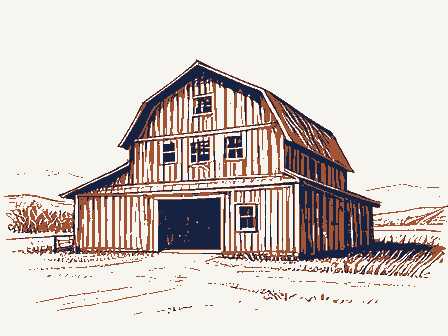
10-300a UNITED STATES DEPARTMENT OF THE INTERIOR NATIONAL PARK SERVICE RECEIVED AUG 2 1 1979 NATIONAL REGISTER OF HISTORIC PLACES NOV 6 1979 INVENTORY -- NOMINATION FORM Henny Barn, Flat Rock Vicinity, Seneca County, Ohio ITEM NUMBER died in infancy so there are no direct descendants. Eliza Ann Henny died in 1881, but, of under the initials "S. Henny" and "E.A. Henny." The Heter and Hankhammer family history for some reason, the 1896 atlas seems to show part of the farm that this barn was part but it is not really clear how she fits into the picture. The barn was probably built by Samuel Henny (family name also spelled Henney DATE ENTERED FOR NPS USE ONLY lists one other possible child for Samuel and Eliza Ann Henny,Amanda Collins by other members of the family),who owned the land from at least 1874 to his death in PAGE SPECIFICATIONS OF PATENTS - SEPTEMBER 4, 1877.
verse section and a horizontal section on lines nouth, Nebr. view, and horizontal section on line z z, Fig. 4, ofa corner-post, showing connection with J. E. MORRISON, Cass and off into horizontal pipes F', at right angles line o c, Fig. 8, of a post that is not tied to the building, and a rear view of the same. water is adjusted by a valve, F', at the in- Similar letters of reference indicate corre- The and thereby the ressel is steered in either di- This invention relates to improvements in the method of constructing frame buildings Similar lateral pipes G, with adjustable valves G' at the point of intersection with thickness, (for which Letters Patent havehere- pipe E for steering the vessel when propelled cember 26, 1876, and numbered 180,690,) so that the entire building may be finished in its and without the use of timber for the posts, beams, rafters, &c.
zles of various discharge-pipes, together with The inrention consists, essentially, of the frrtive propelling and steering capacity. also, of the connection of the posts with the ratter-bearing plates and siding-strips; and, finally, of the construction of a post that is I claim as new is- In combination with the water-supply tank, not tied to the building by a girder or beam. By referring to the drawing, A represents the supporting-posts, which are made of two branching off at right angles from pipes F valves for steering the vessel in either direc- tance from each other and bolted firmly to the beams B, which are made of several planks WILLIAM FRANCIS MORRISON. interposed between the upright planks of the W.J. DESPAIN, t the water J. N. WISE, The lateral post connecting girders F are Tank J. W. JOHNSON, passed through mortises of the plank-posts. JOHN W.
HAINES, and secured rigidly at the meeting ends or *l. but at J. W. JENNINGS. post and then placed in position, the girder ends being then inserted and connected by a which keys are both spiked to the girder ends, and J. Slanser, La Ruo, Ohio. [Filed July of the ves- the plank post by two wedge-keys, a, running To all echom it may concern: in opposité directions to each other, as shown Be it known that we, WILLIAM R. MORRIS in Fig. 1.
and JosEPa SLANSER, of La Rue, county of The girders Fare connected to the corner- Marion and State of Ohio, have invented new and Improved Frame Baikding, of which inserted, turned, and placed in position in the Ihehes off the following is a specitication: nection with the drawings, and then pointed ne, being Figure 1 represents a front elevation, and ends on the ratter-bearing plates D, which are 9,1877.1 Witnesses: against the closed end of the pipe caused by rigidity to the building. the discharge of the water along throngh the plank posts with the girder-joints and ends; erected in cheap manner,entirely of planking, substantially as deseribed. The invention will first be deseribed in con- girders and rafters; and Figs.7and 8 are, re- The planks are placed at some dis. The keys and girder-joint in backward direction.
tersection with pipe F above the water-line, the closed end of the pipes, gives a very ef are finally rigidly locked to the mortises of posts A bya similarly-recessed key,a,that is and y y,Fig.1,of a post and girder-joint. is more or tion of the vessel. out in the claims. ELLING VES- joint of two girders by a recessed key,a,that harges the r pipe D, Figs. 4, 5, and 6 are a side elovation, end An additional pipe, F, extends at a suit- able inclination from tank A, and brancles a new and thereto, thrrough which the outflow of the sponding parts. pipes E, are applied near the forward end of tofore been granted to us nnder date of De- The water surrounding the vessel is but lit- dle agitated, as the operation of supplymg the wate?
to the tank and the discharging of the produces ouly a small effect on the same, the water being discharged at a very slow motion, The recoiling force of the confined water on Having this described my invention, what and E, and being regulated by adjustable posts, so as to form therewith a compound C. P. MOORE, mortises of the hling pipe sccond recessed top key, b, of less width, Ihe body of 194,836. FRAME BUILDINGS. W. R. Morris to unite the same. pipe ver by the bolted to the girder, which is lually locked by wedge-keys, as shown in Pigs. 4, 5, and 6.
te Vertieal vater may is first passed through the mortises of the ie rraction ereaetion this manner be shipped to any point,and and steering purposes tion during its forward and return motion, several parts and finallyputup in strong and Farm and other buildings of all kinds may in plank construetion that gives strength and by the use of planks of suitable length and vertical transverse section on cording to the size of the building tobe upper or gonneeting. end view, of my device. A represents a piece of sheet metal, cu valed with tenons e, that enter mortises of the rafter bearing plates D, so an to prodace tangs b b, to which are soldered the wires The piece A is somewhat curved, as shon Fig. 4, in order to conform to the shap erive the horizontal siding-boards H.
at right angles in opposite directionn, bu A horizontal niding-strip, G, runs below the C represents the pin for attaching the A suitable piece of elastic wire is pointes one end, and the other is bent, as showi not tied to the building by a girder or beam, in which cases thé post A is strengthened by thereafter at about sixty degreex, in order a brace construction, A', as showu in Figs. ings are made in the same plane, but the tl and attached to a central bolt and nut, g, and is inclined thereto, as illustrated in Pig.
4, end e' thereby constituting the spring for h- ing the pin iu its normal positiou away fi The binge and catch for the pin are sti pound plank-frame buildings is perteeted and up from the body of the piece A by detach rectangular pieces e c of the same on thre their sides, the attached side of the binge ing one of those at right angles to the len terx Patent- of the piece A, and that of the cateb be 1. The combination of the recessed and ene of the sides parallel to the axis of tenoned upper end of the plank-post A with the mortised rafter-plate D and lateral sup- simply bent as shown in Figs. 4 and »,: porting piece DY, substantially as and for the subserve the functions above named. 2.
The combination of a compound plank- galvanized, tinned, or plated, if made of b a trussed brace, A', resting on end shoes and center stiffening-bolt g, substantially as speci- of the pin to the cuff, and the latter is inser within the sleeve of the dress or coat. On WILLIAM R. MORRIS the pins a is caused to enter as tar as it go into the fabrie of the sleeve, care bei Witnesses : taken to prevent its appearance on the o The fabrie is then made a little sla between the pius a a, and the otber pin is serted, thereby securely attaching the cuff In order to release the cuff, the fabric simply pinched up between the points of t pins until the same are uncovered, when t cuff may be withdrawn from the sleeve.
My derice in especially adapted for attar ing ladies cufts to the sleeves of the dres: Troy, Rensselaer county, State cf New York, when the absence of a suitable under-garme necessitates the pinning of the cuff to t provements in Cufl-Pasteners; and i hereby the glittering bead of the ordinary pin is t actly described, as follows. comfort, if inside, to the wearer; if outside, porarily but securely attaching linen cuffs to some one else. the sleeves of dresses or coats; and it con The tendency of gentlemen's cuffs, when : tached to the shirt-sleeve, either to fall or combinations of parts, as hereinafter set forth the hand or disappearnp the coat-sleeve, re ami claimed ders my device of nearly as great utility Having thus described my invention, wha claim as new, and desire to secure by Lette the male sex. the sleeve. JOSEPH SLANSER. rendered stronger and more durable. purpose described.
DAVID BAUGHMAN. JOHN A.HAWK, the same plane. This invention relates to devices for tem the rigid interloeking of the posts and rafter- In using the deviceit is attached byme the piece A. its point is liable to canse d In the aecompanying drawings,Figure 1 struck up into the form shown, ad has vice to the cuff, and is constructed an follo Fig. 2, once at about thirty degrees and to fori a triangular shank. The first two bo the posts, to form thus a rigid stiffening of Im this manner the construction of our com- piece A. The portious so cut away are tl post, A, which is not tied to the building, with Troy, N. Y. [Filed July 24, 1877.1 To all ichom it may concern: dress-sleeve from the outside, in which ci attached; Figs. 3 and 3.
plan views, respect- ively, of the lower aud upper sides of the I P'atent; is- seated at the ends against shoes g',bolted to inelined rafter.bearing plate D from post to the cnff.The wires a a are pointed and1 represents a part of a enf'baving my fastener fiedl. DRAWINGS OF PATENTS, SEPTEMBER 4, 1877. W.7. KORRISON. WITHESSES: No. 194,837. Fig.1. SPECIFICATIONS OF PATENTS - DECEMBER 26, 1876. My invention consists of'a sealp for covering passed throngh the face-plate it is only neces- the face-plate of a lock. naid sealp having a sary to make a hole in the scalp at the proper point of a size that will admit the body of the flange at the other, all as bereinatter deseribed.
In the accompanying drawing, Figure 1 is a hook or lock, a, at both edges, and slipped a perspective view of a casket-lock which em- on over the face-plate d in the same manner The of the same, with the scalp and face-plate de- view of a door lock which embodies my inven- heads, are formed in the face-plate, and the face-plate and scalp of said lock, and Fig. 5 is enough to only partially uncover the serew- an end view thereof, showing the face-plate holes in the face-plate, as clearly shown in In the class of locks shown in Figs. 1 and 2, when desired to have the face-plate silver- cnre the lock the metal composing the scalp is so thin that the portion of it immediately plated, the whole angle-plate A, which consti- tutes one side and face-plate of the lock, is made of brass, or sometimes a piece of brass screw, which will not only make a neat finish.
the whole lock_is attached to said angle-plate, but will permanently secure the scalp to said the face-plate is polished, and the entire struc- The face-plate A silver-plated scalp for a face plate of this thereby necessarily depositing silver apon all class of locks can be furnished cheaper than parts of the lock, the interior as well as those a plain brass face-plate can, and besides cheap- parts which are exposed to view, and consum- ness has all the advantage of furnishing the ing a large amount of silver or other plating lock at completion with an unsoiled, newly- polished face-plate, which cannot be the case is then burnished or polished in any proper where a face-plate is made and tinisbed when manner, atter which the keys and link or sta- which requires much manipulation to attach less handling of the lock, so that the polished 1 claim as ms invention- 1.
In locks hraving a finished face-plate, the somewhat soiled, so that it reguires furbish- scalp B provided at one edge with a hook or J make the entire lock of iron or other snit- halt-lock, a, and at its opposite edge with the able material, and fit the keys and links to angular tlange, substantially as described, and the lock, so that there is no occasion for fur- for the purposes set forth. ther hanlling, except as hereinafter mentioned. 1 form a thin covering of brass or other ma- halt-lock,a, in combination with the edge of terial suitable for plating, which covering I the face-plate proper, substantially as de- sealp 1 turn a hook or halt of a tinsmith's scribed, and for the purpose set forth. lock, a, which hooks over, or locks on, the FRANK W. MIX. the angle of the lock a, fully equal to the O. D. HUNTER, width of the face-plate b, 1 form an angle in N. TAYLOR BALDWIN.
the sealp by turning down a flange, as clearly for the link or staple to enter the lock is also kealp is then polished, plated, and burnished Morris and Joseph Slanser, La Rue, Ohio. in any proper and usoal manner, after which [Filed Sept. 2, 1876.] it is slipped endwise on the lock so as to cover its face-plate, as shown in Fig. 4, the lock a firmly seeuring one edge in place, and two Be it known that we, WILLIAM R. MORRIS small pins or rivets, c o, are added to perma- counts, and State of Ohio, hare invented a new and Improved Frame Building, of which resents an end view of our improved construc Simila and scalp detached. ing np before shipping. over the countersunk holes will be swaged For that class of loeks which have serews and JoSEPH SLANSER,of Ia Rue, Marion angular and useful Improvemeuts in Loeks, of which tinished surface.
the following is a specitication: book or balf lock at one edge ani an angular screw. In Figs. 3, 4, and 5 a lock of this bodies my invention. Fig. 2 is an end view tached from each other. Fig. 3 is a front Fig. 4 is a longitudinal section of the quiring - down into said holes by the head of the ing-po 1- ture is immersed in the bath for plating portion of the plating necessarily becomes term the scalp B. Upon one edge of this Witnesses : To all ichom it may concern: br to all other locks, such as sewing ma- In the accompanying drawing, Figure 1 rep screw-holes,countersunk to fit the serew. 728 formed in the scalp at the proper point.Tbe posts. and vert largrol SPECIFICATIONS OF PATENTS - DEOEMBER 20, 1876. together, as shown and describod. 2. The combination of the recessed posts with the lateral girders, and with smooth and aml vertical sections of a post and girder- WILLIAM R. MORRIS.
Similar letters of reference imdicate corre. The object of onr invention is to provide an E. P. COZER, improved method of erecting frame buildings thickness, from which the posts, beams, joists, enabled to put up such buikdings with great 185,69l. GoVERNORS. James M. Napier, facility, a saving of timber, and without re- Lambeth, England. (Filed Oct. 7, 1876.] quiring ekilled help. To all ichom. it may concern: posts abd beams of several plauks that are Be it kuown that 1, JAJES MURDOCH NA- bolted together, and locked to the girders Dr PIER, of York Road, Lambeth, in the county The posts support the roof by of Surrey, England, have invented new and usefil Improvemeuts in Speed Regulators or Gorernors, which improvements are fully set In the drawing, A represents the support- forth in the following specification, reference ing-posts nsed for our improved frame build.
being had to the accompanying drawings. ings, which posts are made of two or more planks of suitable dimensions, according to lating or governing of the speed of motive- the size of the buikding to be erected. Smalier houses require planks of less thickness, while erned by the opening and closing of a valve, or by other equivalent means. tween the upright planks of the posts; and if only one beam-plank in used, the space be- tween the remaining planks of the posts is This vessel is rotated by being placed in con- nection, by suitable wheels, pulleys, or other convenient mechanical means, with the en- bolted together at the points of connection, gine, the speed of which is to be regulated or Figs. 6 and 7.
The joist» O are seeured on the beams B, and suitable bearing-strips b of end or portion of this tube or vessel passes into the rotating vessel at its upper end and vessel a hollow arm projects toward and ter- posts in the same manner as the beams, the minates near the inner circumference of the top part of the post is cut toa tapering angle to support at one side the rafter-bearing plates pieces D' that are spiked together add to the the sotating vessel, finds its lerel in the sta- to is so placed that, when motion in given to the rotating vessel, a portion of the fluid in it parts, is obtained at a considerable saving of in forced in at the oritice of the stationary timber and labor.
Weareuware that frames of dwellings have at the orifice increases, by an increase in the been constructed of horizontal planks laid to- speed of rotation, the fluid rises higher in the gether at the corners, as in patent 140,943; speed of rotation given to the rotating vessel we claim as new, and dosire to secure by Let- 1. The combination of the ports made of a Huid as completely as possible in conformity with that of the vessel by internal projections 729 Witnesses: forth. MYRON ELLIS. sponding parts. JOSEPH SLANSER. wedge-pieces. fposts and The invention consists in constructing the 1;and Figs.6 and 7are detail horizontal that constitute the beams are interposedbe by the use of planks of suitable length and and to the fluid contained in it.
able flnid.placed on a spindle or in bearings &e.,are formed,so that any person may be 5 are detail horizontal sections of the posts, recessed wedge-pieces, substantially as set augular plates and plate-bearers spiked to other engines which are capable of being gov- larger structures, as barns, stables, dc., re- quire planks of greater strength. The planks 1 employ a vessel formed to contain a suit- governed by it, amd the tuid, when placed within it, rotates with it. diagonally stiffened by suitable brace-pieces The sills E are applied to the base of the hollow arm, at or near its extremity, is an D, ani at the ofher side the plate-bearing tube or vessel, and as the pressure of the doid statiouary tube or ressel, and so the beight of but we do not claim such constrnction.
the tluid raries more or less according to the Having thux described our invention, what ters Patent, ix- number of plankk, and the beams and sills The planks of posts and beams are tirmly and the post-connecting girders F are firmly secured by outer grooved or dovetailed and 1inforce and sustain the rotation of the inner smooth wedge-pieces a,as shown in orsupports,so that it can be easily rotated. filled by a short piece plaeed therein. DRAWINGS OF PATENTS, DEO. 28, 1876, J. C. MERRILL. No. 185,691 No.185,688 185,689. W. R. MORRIS & J. SLANSER. J. M. NAPIER. No 185,690 Patenied Dec. 26, 1876. THE GRAPHIC CO.N.Y WITNESSES: TO HAER BRANCH CHIEF Send-back _ Re-submit .
OTHER ARCHEOLOGIST KEEPER TECHNICAL CONTROL Maps HISTORIAN National Register Write-up Property Federal Register Entry United States Department of the Interior-Heritage Conservation and Recreation Service REVIEW UNIT CHIEF State 11.6.79 Working Number 8. 21. 75. 1758 auept Wm. Drown, 8531 N. C.R. 29, Bellevue, Ohio Photo number / AUG 2 1 1979 northwest Thompson Twp, Seneca Co., Ohio (vic. Flat Rock) March 1978 East and south sides of barn; camera pointing Henny Farm Barn William Drown NOV 6 1979 William Drown Photo number 2%10 NOV March 1978 Henny Farm Barn North and west sides of barn; camera pointing southeast wm. Drown, 8531 N. C.R. 29, Bellevue, Ohio Jim Boroff, 194½ Riverside Drive, Tiffin, Oh. 44883 in, Ohio AUG 2 1 1979 Historic Preservation Office, Heidelberg College, Tiff- Mompson Twp., Seneca Co., Ohio (vic.
Flat Rock) Henny Farm Barn anuary 1979 Photo number 3Q10 South wall and roof of barn; camera pointing Southeast OVERLAY FOR #3 of 1O beam Ltruss dias Interior of barn showing bolting system; east and Tiffin south walls shown; camera pointing southeast January 1979 Henny Barn Historic Preservation Office, Photo number 44/0 January 1979 AUG 2 1 1979 Photo number 5//0 Joints between girders and posts; barn interior, south Historic Preservation Office, Heidelberg College, Thompson Twp., Seneca Co., Ohio (vic. Flat Rock) Henny Barn Jim Boroff, 194 Riverside Dr., Tiffin, Oh. 44883 wall tenon on girder B fenon on OVERLAY FOR plank of Wedge B Tiffin Interior of barn; girder and post joint at southeast January 1979 Henny Barn corner of building Photo number 6q/0 mortised Jim Boroff, 194½ Riverside Dr., Tiffin, Oh.
44883 Tiffin Historic Preservation Office, Heidelberg College, Thompson Twp., Seneca Co., Ohio (vic. Flat Rock) Henny Barn January 1979 on south side Interior of barn; girder and post joint at doorway S 1979 AUG 2 1 1079 Photo number 79/0 OVERLAY FOR # 7 of 10 Hompson Iwp., Seneca Co., Ohio (vic. Flat Rock) Jim Boroff, 194½ Riverside Dr., Tiffin, Ohio 44883 NOV on south wall Photo number 8%/0 Tiffin Interior of barn showing post and rafter construction Historic Preservation Office, Heidelberg College, January 1979 Henny Barn 6 I9ANG 2 1 1979 bracepie ca of post Sideboard. Siding shrip Jim Boroff, 194½ Riverside Dr., Tiffin, Oh. 44083 January 1979 corner Tiffin Historic Preservation Office, Heidelberg College, Interior of barn showing brace pieces at southeast Henny Barn So979AUG 2.
1 1979 NOV AUG 2 1 1979 Tiffin Historic Preservation Office, Heidelberg College, January 1979 plankof beam Henny Barn Jim Boroff, 194½ Riverside Dr., Tiffin, Ohio 44883 Photo number 10g/ Thompson Twp., Seneca Co., Ohio (vic. Flat Rock) Interior of barn showing patent dates stencilled on UNITED STATES GEOLOGICAL SURVEY FLAT ROCK QUADRANGLE STATE OF OHIO 7.5 MINUTE SERIES (TOPOGRAPHIC) DEPARTMENT OF HIGHWAYS DEPARTMENT OF THE INTERIOR 6 1979 Honorable John H. Glenn, Jr. Mr. David Brook Columbus, Ohio 43211 Location STATE Seneca County Name Knox County Fredericktown 11/8/79 Flat Rock vicinity NOV Date Entered Byers/bjr Honorable John M. Ashbrook Henny Barn Fredericktown Multiple Resource Area Also Notified Honorable Howard M. Metzenbaum The Ohio Historical Society Honorable Delbert L.
Latta OHIO State Historic Preservation Officer ENTRIES IN THE NATIONAL REGISTER Interstate 7l at 17th Avenue For further information, please call the National Register at (202)343-6401.
 Block
Block