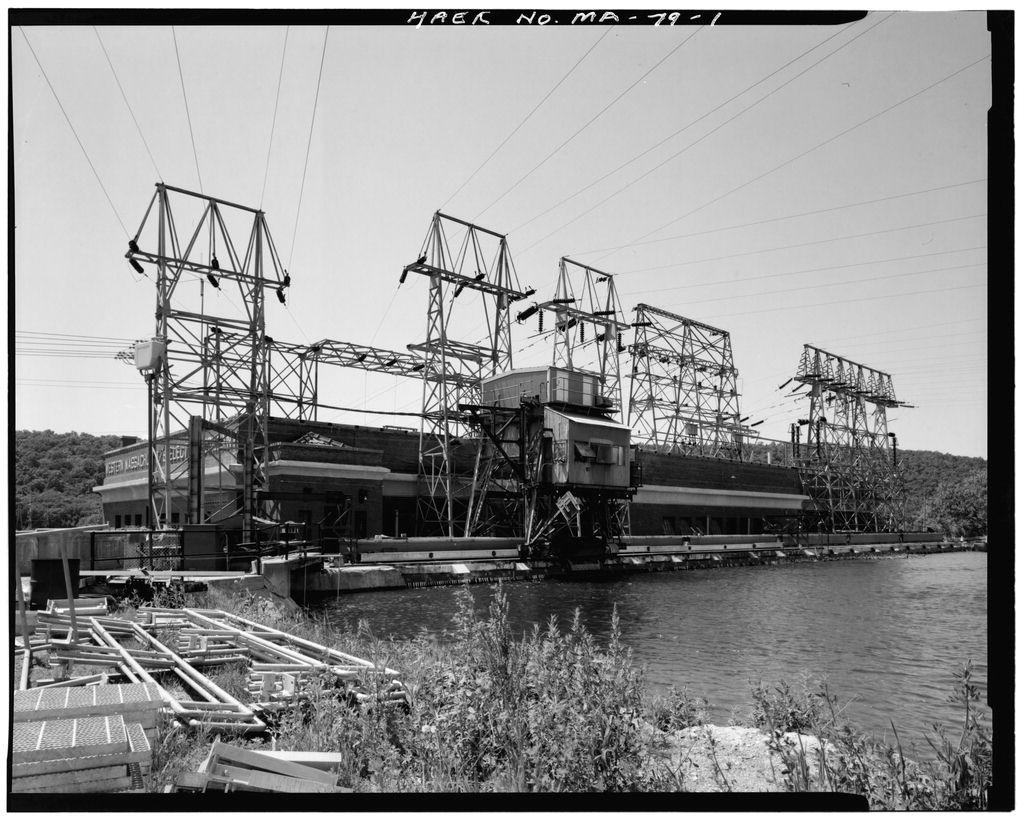
This documentation was undertaken in June by the owner at the suggestion of the Massachusetts State Historic Preservation Office. Prepared Bruce Clouette Senior Historian Historic Resource Consultants 55 Van Dyke Avenue Hartford, Connecticut Cabot Station Electric Generating Plant, Gantry Crane HAER No. MA-79 (Page 2)
The Cabot Station Electric Generating Plant was built in by the Turners Palls Power and Electric Company. Located two miles below the dam on the Connecticut River, the station required a 1-1/2-mile extension of the existing power canal. It utilized 54 feet of head, high by New England standards. Its six turbine-generator sets produced kw, making it the largest hydroelectric facility in New England at the time. Raising the canal embankment in allowed an increase to kw. The plant was considered a notable example of up-to-date hydroelectric engineering, and it received considerable notice in the technical publications of its day (see Bibliography). Descriptions of the plant appeared in major engineering textbooks of the period, including both the Wiley and McGraw-Hill series.
Contemporary technical writers focused on such features as the Broome gates, the arrangement of components within the powerhouse, the smooth inside finish on the concrete penstocks and, consistently, the crane and rack cleaner. Barrows made especially heavy use of the Turners Palls facility in his textbook rev. ed. pp. The crane and rack cleaner were in large part made necessary by the size of the plant. Its Broome gates, weighing five tons each and difficult to lift because of their inclined position when seated, were at the upper limit of conventional rack-and-pinion gate lifters. The alternative to a single movable hoist was therefore 18 separate substantial mechanisms, each with its own motor and gears.
Similarly, the trash racks, 225 feet long and 30 feet high, were a challenge to keep free of debris. A mechanical rake which could travel the length of the rack was one solution; others were a series of fixed conveyor-belt rakes, each dedicated to a portion of the rack, or racks which could be raised and flushed (Rushmore and Lof, p. 97) The mechanical rake was a very inexpensive choice, given the need for the gantry to raise the gates. Neither was it particularly labor-intensive, except for periods of very heavy debris, when the crane could be moved and the rake operated by one person. Sometimes an additional person assisted with dumping the trash out of the rake and keeping it moving in the trough.
In addition to making its way into engineering textbooks, the arrangement at Cabot Station attracted the attention at other hydroelectric companies. The files at Northeast Utilities contain several inquiries regarding the gantry and rack cleaner. In replying to the United Hudson Electric Corporation of Poughkeepsie, the superintendent of stations for Turners Palls Power and Electric Company noted that the trash rake worked quite successfully, sometimes hauling out several hundred tons of trash a day. He nevertheless recommended a greater slope to the trash racks and a wider trough as improvements (Northeast Utilities Service Company files, Document December 21, Cabot Station Electric Generating Plant, Gantry Crane HAER No.
MA-79 (Page 3) Together, the gates, crane, rake and trash trough illustrate the point that Cabot Station was a carefully thought-out, completely designed facility. Reported to be one of the lowest-cost plants of the period (Electrical World, p. its components work together to provide effective and economical solutions to the standard problems of hydroelectric generation. Examples abound, showing the functional integration of components, such as the formation of the penstocks and trash trough integral with the powerhouse foundation, and the water-level tubular gauges which signalled trash-rack obstructions inside the powerhouse.
The crane is significant as another well-designed, original component of a facility that was large for its day and was the subject of much contemporary engineering interest. The crane and rake was fabricated by Exeter Machine Works of Pittston, Pennsylvania, a major producer of large mechanical structures, such as cranes and operating mechanisms for swing bridges. The company also provided the original gates and roller chains for Cabot Station. Cabot Station and all of its components were designed by the engineering staff of Turners Palls Power and Electric Company. P. L. Hunt was chief engineer, assisted by H. M. Turner (hydraulic engineer), and H. A. Moody (powerhouse). The company consulted with A. T. Safford of Lowell and F. P. Stearns of Boston.
The contractor for the gates, penstock and powerhouse was Fred T. Ley of Springfield, Massachusetts, a large regionally-important construction firm. The wider historical context for understanding the features of Cabot Station is the consolidation of the electric power industry, which made possible such large plants. Turners Palls Power and Electric Company was the successor to a company that had built a dam and canal for industrial power at Turners Palls in In the company extended its canal by 800 feet and built a kw electric generating station, but for two years the plant had but a single customer, the Franklin Electric Light Company, and most of the potential power went unused.
Around this time, a group of Boston financiers, under the leadership of Philip Cabot, gained control of the stock of the Turners Palls company. Cabot became president, just as he had assumed the leadership of several nearby utilities that the same interests had purchased, including the Greenfield Electric Light and Power Company, the Amherst Gas Company, the Amherst Power Company, the Easthampton Gas Company, the Agawam Electric Company, and the Ludlow Electric Light Company. Cabot revamped plans to build a low-head, kw plant at the Montague site, instead choosing a larger plant to exploit the full head of a lengthened canal. The new plant, eight times larger than the one built only ten years earlier, supplied power to all the towns in the region.
There was no repetition of the experiences, when 8C# of the available power went unsold. Cooperative agreements with utilities such as the New England Power Company, United Electric Light Company (Springfield), Springfield Street Railway, Northampton Lighting Company, and Northern Connecticut Light & Power made the electricity produced at Turners Cabot Station Electric Generating Plant, Gantry Crane HAEP No. MA-79 (Page 4) Falls available to a wide area. When Cabot retired in the company's board named its flagship station after the departing president.
The gantry crane at Cabot Station consists of a large hoist, with a design capacity of 20 tons, mounted within a tall, electrically-propelled tower of riveted steel construction. The crane travels along rails straddling the 18 headgates on the east (forebay) side of the large brick power station. In addition to its primary function of raising the penstock gates, the crane also has an electrically-powered rake to clear debris from the approximately 225 linear feet of trash rack in front of the penstock openings. Hoists, gearing, motors and controls are protected from the weather by corrugated-metal siding which encloses a housing at the top of the crane and an operator deck about half way up its height. The crane is an original feature of the power station.
Despite some alterations, it retains most of its historic form and materials. The crane's superstructure has four legs, each built of box-section lattice girders. The legs slant forward, so that in plan the crane measures 14 by feet at the bottom and by feet at the top of the legs. The legs are joined at the top by heavy plate girders and at the bottom by latticed box girders. The bottoms of the legs are not joined on the north and south sides, leaving the tower open in the direction of travel. The legs are braced in both directions with latticed paired angles. On the east side of the crane is the open-grill operator deck with a partial enclosure framed out of steel angles. The deck is supported by I-beams riveted to the two east legs.
Measuring 10 feet wide, the deck extends 5.5 feet beyond the east legs, with a shed roof for the overhanging portion. At the top of the tower is a second deck and the 6-foot-high housing for the main hoist and the drive motor. The housing is framed out of steel angles. Its shallow-pitched roof is now covered with corrugated fiberglass panels (originally corrugated steel). A ladder on the north side of the crane provides access to the operator deck, from which the top deck may be reached by a second ladder mounted on the south side exterior. The crane travels on four pairs of 18-inch-diameter, cast-iron, double-flanged wheels, running on 75 pound rails spaced feet on center. The motor for crane movement is located at the northeast corner of the top housing.
Power is transmitted to one wheel in each set by a series of 3-l/2-inch shafts and bevel gears mounted on the outside of the tower. Power for the drive motor, the hoist motor, and the trash-rake motor comes from a trolley attached to the southwest leg; the crane runs on 5-phase, 60-cycle, 550-volt current. Cabot Station Electric Generating Plant, Gantry Crane HAER NO. MA-79 (Page 5) The main hoist is mounted on I-beams atop the plate girders joining the legs; steel-plate frames support the motor, gearing, and drums for two wire ropes. The wire ropes are looped twice around double-sheave blocks on either side of the large hoist hook. The hoist raises the intake gate for the six penstocks within the concrete foundation of the powerhouse.
Each penstock has three gates, for a total of 18 gates ranged in a continuous row between the crane's rails. The original gates, replaced in the were steel-plate, Broome-type gates, running on roller chains. They weighed about five tons and measured 10 feet wide by 16 feet high. Metal covers (not seen in an early photo of the crane) protect the present gates. To raise the gate, the covers are removed, the crane is moved along the rails to a position over the gate, and the hook lowered to engage an eye atop the gate. Large eyebar links are sometimes used between the hook and fate. The gates drop by gravity. In addition to raising the gates to their fully-open position, the crane can raise them completely out of their guides.
The 6-foot-wide rake of the mechanical rack cleaner has 15 teeth, formed from forged steel bars. The rake is shaped like a cupped hand, with teeth mounted 5 inches apart on two rods and held in place by pipe spacers. The rods also carry two sets of 8-inch-wide guide rollers for the rake. The rollers initially run in a segment of curved track extending from the bottom girder on the east side of the crane outward to the top of the trash rack. Then, as the rake descends along the face of the rack, which typically is submerged 30 feet under the surface and is slanted outward at an angle 16 degree from vertical, the rollers are guided by the trash-rack bars themselves. Two sets of wire rope run from the rake to machinery on the operator deck.
One set is for raising and lowering the rake along the racks; the other is for lifting the front of the rake and then lowering it, so it can scoop up debris. A single motor powers both motions, with a lever-actuated clutch to lift or lower the front of the rake. Between the top of the trash racks and the crane's east rail is a continuous trough. When the rake is pulled out of the water, after have been dragged along the rack, accumulated debris falls into this trough for disposal. The operator deck, in addition to the motor, gearing, and drums for the rack-cleaning mechanism, also includes controls for the main hoist and crane-travel motors.
Two of these appear to be original and are marked "General Electric Patented October 19, and February 2, The other controls and cut-off switches are later modifications. Cabot Station Electric Generating Plant, Gantry Crane HAER No. MA-79 (Page 6) The crane has a small boom made up of welded angles mounted on the upper part of the southeast leg. This "jib crane" is a later replacement for a similarly-sized wooden crane which originally was mounted on the northeast leg. Its function is to lift large pieces of debris or sections of trash rack. Another addition is a wood and steel ice-boom, a paddle-shaped device attached to the bottom girder at the crane's southeast corner.
When lowered into the forebay in front of the trash racks with the crane moving, the boom sweeps ice away from the intakes toward a sluice originally intended for passing logs. The crane today is substantially in good condition. Some minor modifications have already been noted the replaced jib crane, added ice boom, replaced controls, and fiberglass roof panels. The trash-rake hoisting mechanism incorporates a modern reduction gear. A large I-beam has been added to the inside of the east legs for holding sections of trash rack being removed for service. Formerly, there were small, square, steel pivot-sash windows on the east side of the top housing, similar to those still extant on the east side of the operator deck enclosure. They have been replaced by doors.
The outside catwalk for the top deck has been extended on the south and east sides. The corrugated-metal siding has been renewed. Sheet-metal covers over the wheels' bevel gears have had their seams welded. The 72-year-old crane continues to perform all of its original functions. However, it does not conform to present-day code standards, and ongoing repairs are required to keep it operational. Replacement spare parts are no longer available.
Abercromie, Fred C. The Turners Falls Power and Electric Company, A Public Facility Since Turners Falls: Turners Falls Power and Electric Company, Barrows, H. K. Water Power Engineering. New York: McGraw-Hill Book Company, 3rd rev. ed., Connell, B. R. "The Hydroelectric Development of the Turners Falls Power & Electric Company at Montague City, Mass.," General Electric Review 20 (March Engineering Society of Western Massachusetts. "Inspection of Turners Falls Power & Electric Company's Hydro-Electric Development at Turners Falls, Mass., November 22, Typescript, Northeast Utilities Service Company, Berlin, Connecticut. "Largest Hydroelectric Plant in New England." Electrical World 69 (June 21, Cabot Station Electric Generating Plant, Gantry Crane IT A WD HAEE UTrt Ho.
J*A TO MA-79 (Page 7) Hortheast Utilities Service Company. Berlin, Connecticut. Correspondence, contracts, and drawings files, Cabot Station, Rushmore, David B. and Eric A. Lof. Hydro-Electric Power Stations. New York: John Wiley # Sons, 2nd rev. ed., Turner, Howard M. "Hydraulic Redevelopment at Turners Falls, Mass." Engineering News 74 (July 29,
 Block
Block