Post-Cold War downsizing has resulted in a number of necessary changes to Cold War era facilities. Two of the PAVE PAWS sites (Texas and Georgia) are no longer operational and have been partially dismantled. Several engineering projects required at the Cape Cod site have been determined to have adverse effects on the historic integrity of the radar facility. The Air Force, State Historic Preservation Officer, and the Advisory Council on historic preservation entered into a Programmatic Agreement, which calls for documentation of the Cape Cod site before any adverse action. This package fulfills the stipulation for HABS/HAER documentation noted in that agreement. Prepared by: Mandy Whorton, Environmental Scientist, Argonne National Laboratory, 200 Union Ste.
Lakewood, Colorado 17 April CAPE COD AIR STATION, TECHNICAL FACILITY/SCANNER BUILDING AND POWER PLANT (Cape Cod Air Station, Building 002 and HAERNo.MA-151-A (Page 2) Cape Cod Air Station, Technical Facility/Scanner Building and Power Plant The Technical Facility/Scanner Building (Building and attached power plant (Building is the central component of the PAVE (Air Force program name) PAWS (Phased Array Warning System)4 complex and, for this reason, it is the only facility on Cape Cod Air Station eligible for the National Register of Historic Places. The self-contained radar and power plant perform all the functions required for the SLBM-detection and tracking mission, including detection, processing, and characterization.
(Although the radar has been generally powered by commercial power, the attached backup power plant can provide power in case of power outages or interruptions.) Technical Facility/Scanner Building (Building History Planning for the construction of the Technical Facility/Scanner Building began in (although initial planning for the PAVE PAWS program dates back to The U.S. Air Force's Electronic Systems Division (ESD) (under the leadership of LtCol Paul T. McEachem) was the program manager for PAVE PAWS and responsible for the construction, testing, and initial operation of the Technical Facility/Scanner Building. On 23 May ESD announced the selection of Otis AFB, Massachusetts as the east coast site for PAVE PAWS.
(The PAVE PAWS site became a stand-alone installation and was renamed Cape Cod Air Station after it became operational.) On 12 April ESD awarded a million contract to Raytheon's Equipment Division, Wayland, Massachusetts, for the procurement of the east coast PAVE PAWS radar system, which included construction of the technical facility and required electronic and radar equipment. The contract was supplemented in May when ESD exercised options worth an additional million. (General Electric unsuccessfully protested the award.) Raytheon awarded a subcontract to the Gilbane Construction Company, Providence, Rhode Island, for the Technical Facility. Groundbreaking ceremonies were held at the Flat Rock Hill radar site at Otis AFB with approximately 40 people in attendance.
Work on the foundation was completed in March Structural steel was in place by May. In November, Gilbane Construction Company completed the installation of the steel electromagnetic pulse (EMP) shield and aluminum exterior siding. By March all plumbing, heating, ventilation, air- conditioning, and electrical work were completed on the building, and Raytheon began to move 4 Early reports translate the PAVE acronym as Precision Acquisition Vehicle Entry. It is also referenced in some documents as Perimeter Acquisition Vehicle Entry. Recent Air Force materials on the system, however, distance themselves from these designations and characterize it instead as an inconsequential program name.
CAPE COD AIR STATION, TECHNICAL FACILITY/SCANNER BUILDING AND POWER PLANT (Cape Cod Air Station, Building 002 and HAERNo.MA-151-A (Page 3) radar and computer equipment on site. (Testing of equipment occurred at Raytheon's Massachusetts offices concurrent with the construction of the Technical Facility.) System performance testing of the Technical Facility began in early April and was completed 16 January On 12 April ESD accepted the site from Raytheon with minor abnormalities to be corrected. On 29 February Site 1 radar facility was turned over to Air Defense Command for operation. Description The Technical Facility/Scanner Building is a ten-story building having a trapezoidal base or footprint with two walls tilted 20 degrees from vertical, narrowing to an equilateral triangular roof.
The metal-framed building is protected with steel paneling to provide an electromagnetic protective (EMP) shield. Foam-filled aluminum ribbed panels finish the exterior. Radar plates on two sides are welded to the EMP shield. Its roof is steel-framed, sheathed with composite stone aggregate and a rubber membrane. The building's total height is 105 ft (plus an 11-in steel fascia). There are six elevations on the building. Faces A and B (elevations B and F) contain the radar faces. Face C (elevation D) is the large wall on the back of the building that attaches to the power plant. Elevations B, F, and D are square: 105 by 105 ft. Elevations A, C, and D are triangular to accommodate the tilt of elevations B and F.
Elevation A is shaped as an isosceles triangle, and elevations C and D are shaped as right triangles. The windowless building contains entrance/exit doors located on elevations A and D. There is a single louvered vent on rear face (elevation D) and no other fenestration. On each of the array faces, the radar is arranged in a diameter circular pattern of crossed dipole antennas. Each of the two array faces is composed of antennae, of which are active and the rest are dummies. The design of the dummy antennae is identical to the active antennae; the only difference is the activation of power and electronics. Dummy antennae could be activated to increase the overall radar capability. Each antenna unit measures 12-in by 8-in and is set into a rectangular aluminum panel.
Each panel is designed to hold 32 units, although many are not full based on the thinning of elements away from the center (boresight). The units are lined up symmetrically at a 45-degree angle. Dummy elements are configured with transmitter/receiver capability but are not connected to power. The active antennae are connected to a complex network of electronic equipment visible from the on the back of the radar faces, including drivers, exciters, signal processors, radar controllers, data processors, receivers, beam steering units, and communication equipment. The PAVE PAWS radar the AN/FPS-115 represented the first design of a two- faced phased array radar facility.
Because a phased array antenna will receive signals from space CAPE COD AIR STATION, TECHNICAL FACILITY/SCANNER BUILDING AND POWER PLANT (Cape Cod Air Station, Building 002 and HAERNo.MA-151-A (Page 4) only in the direction in which the beam is aimed, the maximum practical deflection on either side of the antenna center is 60 degrees. The overall coverage of the phased array radar system is, therefore, 120 degrees. The facility was constructed in the shape of a triangle to provide coverage that is more complete. The two building faces supporting the arrays cover a total of 240 degrees, with each face having a 120-degree coverage. The array faces tilt back 20 degrees to allow for an elevation deflection from 3 to 85 degrees above the horizon.
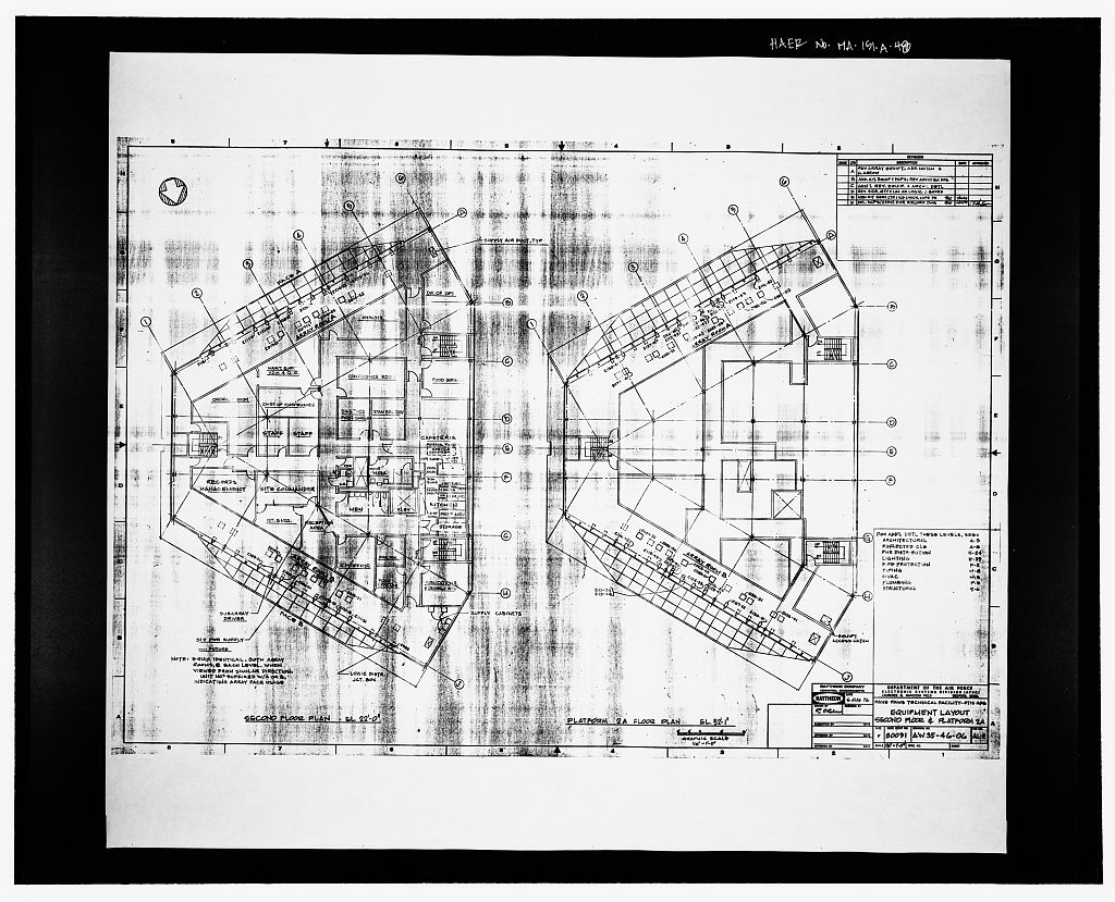
The lower limit is set to provide receiver isolation from signals returned from ground clutter and to protect the local area from a potential microwave radiation hazard. The interior space is divided into 10 floors, including five working levels and 5 mezzanine platforms providing access to the rear array elements. The height of all floors (floor to ceiling) is 10 ft. 1 in except the first and top floors, which measure 11 ft 11 in. The first floor contains the main entrance and several administrative offices, maintenance rooms, and storage spaces. The second floor contains the main administrative and office spaces for the facility, including the commander's office and includes a small employee lounge area.
(A kitchen area was part of the original construction, but equipment was removed, and the area is now a lounge with only a microwave oven and coffee pot.) The third floor houses the computer and radar electronics equipment. The computer room is a secured facility with locks and alarms to detect unauthorized entry. The computer equipment is connected to two Exide 400KVA solid-state uninterruptible power supply units as backups. The fourth floor contains the Missile Warning Operation Center (MWOC), which is the center of PAVE PAWS operation. Original computer equipment in the MWOC was replaced in facilitating other minor revisions of this space.
The MWOC's computer system is designed to rapidly discriminate between vehicle types, calculating their launch and impact areas in addition to the scheduling, data processing, and communications requirements of the launch response. The operation is entirely automated and requires only a few personnel for monitoring, maintenance, and providing a final check on the validity of the warnings. Three people are on duty 24 hours a day, seven days a week to monitor potential missile launches. Simulated missile launches are run on magnetic tapes to test the personnel and the equipment. In addition, approximately one missile is launched from Cape Canaveral, FL per month and tracked by the PAVE PAWS at Cape Cod. The fifth floor houses air conditioning equipment.
The Technical Facility/Scanner building has been owned and managed by the Air Force since its construction. It has undergone improvements, but no major structural changes. The exterior of the building remains unchanged from its original construction. There has been some modification to the interior spaces of the facility to accommodate upgrades to the electronics equipment. CAPE COD AIR STATION, TECHNICAL FACILITY/SCANNER BUILDING AND POWER PLANT (Cape Cod Air Station, Building 002 and HAERNo.MA-151-A (Page 5) Power Plant (Building History The U.S. Navy Facility Engineering Command (NAVFACENGCOM) located in Philadelphia, Pennsylvania, was responsible for the design construction of the power plant in addition to all ancillary structures, utilities, roads, security fence, etc.
at Cape Cod AS. NAVFACENGCOM awarded a contract to the Jefferson Construction Company, Cambridge, Massachusetts, for the power plant structure on 27 September It was of similar construction to the Technical Facility and was completed in April The six original kW generators were acquired from excess Naval equipment in U-Tapao, Thailand. They arrived in September and November and required overhaul before installation at Cape Cod. Cracks discovered in the generator units delayed by two months the operational date for PAVE PAWS Site 1 (Dymond Dymond 1980a; Dymond The original generators were later replaced with more reliable, higher capacity units Space Warning Squadron, Description The radar facility requires immense power to operate; each antenna element annually requires 145 kW.
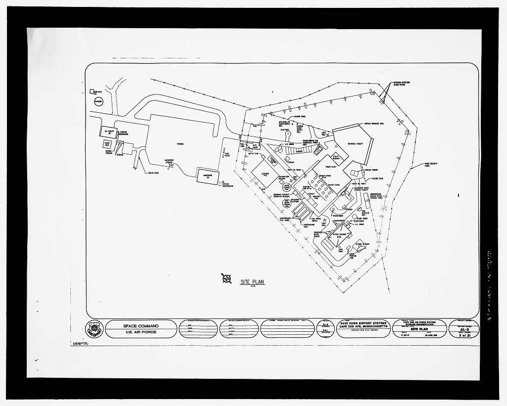
Power to run the radar is supplied primarily through commercial power sources; but a power plant was constructed on site to ensure continuous operation of the radar facility. Commercial power is provided via a substation located approximately one-half mile southwest of the technical facility and is fed from an 115KVA Commonwealth Gas and Electric commercial power line. A second 23KVA commercial power line is provided from the town of Sandwich to the technical facility. Electricity bills of $1 million constitute approximately one-third of the operating budget of the site Missile Warning Squadron, The backup power plant is a steel-framed building with steel paneling, finished with insulated aluminum panels resting on a concrete pad. It measures 143 by 87 ft.
The roof is a steel-framed gable finished by standing seam and stands 55 ft. at the center, sloping to 45 ft. A 28 by 52 ft. walkway connects the power plant to the radar facility. The windowless structure has three single, cyber-locked metal doors: one at the walkway and the other two on the short ends of the building. The power plant currently has five kW generators, with a total site capacity of 7.2 mW. Two generators provide enough power to run the site; a third is kept on line during power generation; and the other two are reserved for backup.
CAPE COD AIR STATION, TECHNICAL FACILITY/SCANNER BUILDING AND POWER PLANT (Cape Cod Air Station, Building 002 and HAERNo.MA-151-A (Page 6) Sources of Information/Bibliography Engineering drawings 134 Architectural, Structural, and Mechanical Construction drawings, dated August 6, by Raytheon Company, are the property of the United States Air Force, Space Command, Cape Cod Air Station. 21 Architectural Site Baseline Documentation drawings, dated 25 June by the US Air Force Space Command, are the property of the United States Air Force, Space Command, Cape Cod Air Station. Historic Views Nine (9) historical photographs, ca. (the photographer unknown) are the property of the United States air Force, Space Command, Cape Cod Air Station. Interviews: Capt.
Jeffrey Cloutier, Support Officer, 6th Space Warning Squadron, Cape Cod Air Station, May Ms. Nancy Fisher, Raytheon Support Services Company, Environmental Coordinator, PAVE PAWS Site 1, Cape Cod Air Station, June Mr. John P. Diehl, Raytheon Support Services Company, Civil Engineering Manager, PAVE PAWS Site 1, Cape Cod Air Station, June Mr. Les Easton, Raytheon Support Services Company, PAVE PAWS Site 2 Civil Engineering Manager, Beale AFB, November Dr. Coy Cross II, 9 RW/HO Historian, Beale AFB, November Mr. Bill Head, Robins AFB Historian, November Mr. Ray Hartsell, Raytheon Support Services Company, PAVE PAWS Site Manager, Site 3, Robins AFB, November Mr. Jim Newton, Raytheon Support Services Company, PAVE PAWS Civil Engineering Manager, PAVE PAWS Site 3, Robins AFB, November Dr.
Richard Sturdevant, AFSPC Historian, Peterson AFB, Colorado, September January and March and Dr. Richard Ekert, AFSPC Historian, Peterson AFB, Colorado, September and March Bibliography Dymond, History of 6th Missile Warning Squadron, December Originally published by Strategic Air Command but now available from the Air Force Historical Research Agency archives (K-SQ-AW-6-HI) located at Maxwell AFB, Alabama. Dymond, 1980a. History of 6th Missile Warning Squadron, January-March Originally published by Strategic Air Command but now available from the Air Force Historical Research Agency archives (K-SQ-AW-6-HI) located at Maxwell AFB, Alabama.
CAPE COD AIR STATION, TECHNICAL FACILITY/SCANNER BUILDING AND POWER PLANT (Cape Cod Air Station, Building 002 and HAERNo.MA-151-A (Page 7) Dymond, History of 6th Missile Warning Squadron, April-June Originally published by Strategic Air Command but now available from the Air Force Historical Research Agency archives (K-SQ-AW-6-HI) located at Maxwell AFB, Alabama. 6th Missile Warning Squadron, Comprehensive Planning Framework: Cape Cod Air Force Station, Massachusetts. Cape Cod AFS: 6th Space Warning Squadron. Likely sources not yet investigated: None Supplemental material: None.
 Block
Block