N. E. Hawkins John S. Lewis City of Youngstown 26 S. Phelps St. Youngstown, OH Storage Facility The Pump House forms the nucleus of the Youngstown City Water Works Complex, a historically significant industrial complex in Mahoning County. The facility was in operation from through and served as Youngstown's only pumping and water filtration station during this period. The complex was critical to the development of Youngstown during the early twentieth century, and is an important record of an early pumping and purification plant. The Pump House, which includes the main pump house and boiler room, dispensed water into the main water lines that sustained residential homes and industrial complexes in the Youngstown City area.
The facility commenced operation in and remained in use until The former Youngstown City Water Works will be redeveloped by the City as an office complex for city use. The three original buildings - - the pumping station, filtration house, and the machine shop - - will be altered or demolished. Documentation of the water works complex to the standards of the Historic American Engineering Record prior to alteration or demolition was undertaken by the Center for Historic Preservation in April and May in an effort to record the municipal history of the city of Youngstown. The report will be donated to the Library of Congress. Center for Historic Preservation Youngstown State University 518 DeBartolo Hall Youngstown, OH YOUNGSTOWN CITY WATER WORKS PUMP HOUSE HAERNo.
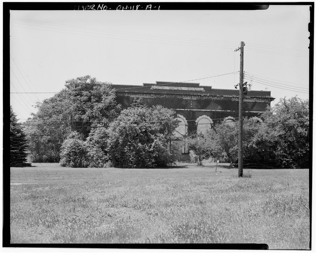
OH-118-A (Page 2) Architectural Description Constructed between and the Youngstown City Waterworks main pump house was an elaborate example of a structure influenced by the Second Renaissance Revival. Designed by John S. Lewis and N. E. Hawkins, the structure was the focal point of the Water Works complex. 1 Today, the Youngstown City Waterworks pump house, located at 160 North West Avenue, stands vacant and awaits reconstruction by architect Anthony Hayak. 2 The pump house is a multi-storied structure with a rear ell which stands on a concrete foundation. The primary facade faces east.
Because the front half of the pump house is the portion most likely to be seen and toured by the public, it sits closest to the road and is more ornamental than the rear ell and the other buildings of the complex. There have been no notable additions to the outside of the structure; however, a smokestack on the north side of the building was removed in as was a greenhouse, formerly located on the building's south side. 3 The pump house is constructed of a modern extruded brick laid in a running bond. The east side, or primary facade of the building, has a brick stepped parapet roof line which also runs along the north and south roof lines of the main pump house. A white glazed terra cotta banner containing the words "City Water Works" is located within the primary facade parapet.
The roof line that is continued on the rear ell is simply a straight line parapet. A white glazed terra cotta coping located above the parapet outlines the entire structure. Below the parapet on the primary facade is a white glazed terra cotta cornice extending around the structure. Below this cornice is a broad band of bricks with two designs composed of three terra cotta diamonds vertically placed over the main archway and one design of three vertically placed terra cotta diamonds in the south and north corners. The primary facade of the building contains a symmetrical group of arched windows and a centered doorway with a concrete staircase. Each arch, constructed with one large keystone, forms a semicircle to each side of the window until it reaches a brick impost.
The center window is 9 feet, 9 V* inches wide and 12 feet, 4 inches high. All other windows are 9 feet, 9 1 >4 inches wide and 19 feet, 11 inches high. 4 Brick pilasters surround these seven arched windows and stylized pilasters are located under each of the diamond designs. Between each plain brick pilaster and above the windows is a set of corbelled bricks. The main entrance, located within the center arch, is more ornamented. White glazed terra cotta extends to the bottom of the x The Mahoning Valley Historical Society. Builders of Youngstown, Youngstown City Waterworks, City Water Works Department: A Souvenir of Opening Days, May 2 Eugene Leson, Engineer in Charge, Youngstown Water Department, Interview by Erin Pogany. Youngstown, Ohio.
14 April 3 T/?e Youngstown Vindicator, 21 September p. 13, col. 2. 4 Blueprints of Primary Facade. City of Youngstown, Ohio. Proposed New Pumping Station, North West Ave. February YOUNGSTOWN CITY WATER WORKS PUMP HOUSE HAERNo. OH-118-A (Page 3) imposts. The doorway itself mimics this theme. The lintel, of the same material, is very decorative with a highly ornamented supporting bracket on either side. Eight concrete steps lead up to this doorway. They are sided by concrete handrails, painted brick red, and topped with a saddlebacked coping, ending with a large concrete newel post. The north side of the pump house continues the same window theme as the primary facade but contains only three windows.
Just below the center window, a brick lined ramp begins at ground level and leads into the basement. The north side of the rear ell contains three windows to either side of where the smokestack once stood. The windows vary in size from 11 feet 1/4 inch wide and 9 feet 5 inches high to 12 feet 3/4 inches wide and 11 feet 4 inches high. 5 The windows each have 54 panes. Brick pilasters separate the windows as on the primary facade but are smaller in width. A concrete coal bunker is located on the south side of the pump house. After three arched windows which imitate the opposite side, this coal bunker begins and runs the length of the south side of the rear ell onto the B&O Railroad. 6 The bunker is 100 feet 7 inches long.
The part of the bunker which is attached to the structure is completely enclosed on its south side. The top of the bunker is open, allowing coal to drop in. A series of small doors lead from the coal bunker to the inside of the rear ell which housed the boilers. The portion of the bunker which runs off the building also has a flat top, but underneath there are three arched openings. Above the coal bunker are six square windows. These windows have the same dimensions and number of panes as the windows on the north side of the rear ell. The west side of the pump house has three arch windows, the center window, originally located over a double door, has a dimension of 9 feet 9 34 inches wide and 10 feet 7 inches high.
The west side of the rear ell, or the apex, contains three square windows equal in size to the windows found to the north and south. The center window sits directly above a large entrance way which was originally a double door. 7 The interior of the pump house is more elaborate than the interior of the rear ell, or boiler room. The walls are constructed of a white enameled brick veneer while the walls of the boiler room are red extruded brick. Within the pump house is a concrete balcony which originally sat over the pump pit. It is 3 feet wide on the east and west sides and 9 feet 6 inches wide on the north and south sides. 8 A wood floor currently covers the pump pit opening where the equipment once stood. Between the arched windows are pilasters replicating those on the outside.
They climb just above the height of the windows and end in a corbelled style. All of the window vents within the structure are operated by a hanging chain. 5 Blueprints of North Side. City of Youngstown, Ohio. Proposed New Pumping Station, North West Ave. February, 6 Sanbom Map, 7 Blueprints of West Side. City of Youngstown, Ohio. Proposed New Pumping Station, North West Ave. January, 8 Blueprints of Interior Pump Pit. City of Youngstown, Ohio. Proposed New Pumping Station, North West Ave. December - Revised YOUNGSTOWN CITY WATER WORKS PUMP HOUSE HAERNo. OH-118-A (Page 4) The small structure connected to the west side of the primary facade orginally contained an engineer's bathroom, a firemen's bathroom, and an oil and storage room. The structure is 15 feet wide and 28 Vi feet long.
9 A white terra cotta coping tops the straight lined roof. The west side of this building has three twelve paned windows with an unadorned pilaster connecting the west side to the north side. On the east side, located just left of center, there is a 6 paned wooden door with 3 panels. A white glazed terra cotta cornice and corbelled bricks top the windows and door. The walls inside are also constructed with white enameled brick veneer while the ceilings are beaded. Historical Evolution The pump house was constructed between and and replaced the original pump house constructed in on the north side of the Mahoning River. The new structure was built to better service the growing city with filtrated and softened water.
10 Operation of the Younqstown City Water Works Pump House, The Pumping House and Station was completed and put into use on May The station was built in order to accommodate the future expansion and growth of the city's water needs. When the facility opened, the station had a combined pump capacity of roughly thirty-five million gallons of water per day. By when the Youngstown City Water Works closed, the pumping system had a combined capacity of million gallons per day.
The equipment in the station in included: one William Tod Company vertical triple expansion pumping engine, three Worthington centrifugal pumps and two Allis-Chalmers electric generators directly connected to the Kerr turbine engines, one General Electric Switchboard, four 500 horse power Stirling water tube boilers fitted with Green chain grate stokers and Foster superheaters, two DeLaval three-stage centrifugal boiler feed pumps with Cochrane feed water heaters, one Hyle & Patterson coal handling device, one Girtanner-Davies ash handling device, one Euclid Crane and Hoist Company and oneTen-ton traveling crane. Finally, the pump house had one reinforced concrete chimney 238 Vz feet high with an exterior base of 30 square feet and an inside diameter of 10 feet.
11 Water received from the filtration house was distributed throughout the main system. It was necessary to divide the total load of the pumping station between the various units, or pumps, for maximum pumping efficiency, 12 Water entered the pump house through a class "A" 9 lbid. J0 Joseph G. Butler History of Youngstown and the Mahoning Vailey, Ohio, Chicago: American Historical Society, pp. "The Mahoning Valley Historical Society. A Souvenir of Opening Days. 12 Haro!d Babbit and James Dolan, Water Supply Engineering, New York: McGraw Hill Book Co. p. YOUNGSTOWN CITY WATER WORKS PUMP HOUSE HAERNo. OH-118-A (Page 5) 48 inch suction header pipe on which a Tod Triple Expansion pumping engine was installed, it had an individual capacity of 7.5 million gallons per 24 hours at 220 feet head.
Head is the force or pressure exerted by a liquid or a gas. It is equal to the amount of energy per unit weight of water. Two 18 inch single-stage DeLaval Centrifugal Pump powered by a horsepower DeLaval Turbines connected by helical reduction gears were also installed on the Suction Header. The capacity of these pumps were 15 million gallons of water per 24 hours at 380 feet head. Two 16 inch single stage DeLaval centrifugal pumps powered by 900 horsepower DeLaval Turbines connected by helical reduction gears were added to the Header as well. Their capacity was 10 million gallons of water per 24 hours at 380 feet head. Pumps were operated either in a series or parallel thus allowing for more flexibility in the service.
If two identical pumps are operated in a series the effect will be an equal/same discharge of water yet the head will be enhanced by two. Identical pumps operated in parallel have a reverse effect. The head remains the same while discharge will be greater by two. 13 When steam turbines are connected to centrifugal pumps, reduction gears are necessary. The gears equalize the speed of the driving mechanism to the pump, allowing it to power the pump. The centrifugal pumps rely on centrifugal force to create a partial vacuum to draw in water and are considered the best pumps for water works use. 14 The water was forced by the Tod triple expansion and DeLaval pumps into a Discharge Header.
The Discharge Header forced the water out through one of the four service mains, two of which were high pressure 30 inch mains and two of which were low pressure 36 inch mains. The Discharge Header was aided by two additional Worthington Centrifugal Pumps directly connected to Kerr Turbines with a combined capacity of 16 million gallons per 24 hours - 8 for each Worthington Centrifugal Pump - at 240 feet head for each pump. The four service mains are necessary for the water to travel. The 30 inch high- pressure main was smaller to obtain greater pressure thus allowing the water to be distributed over a greater distance. The low pressure 36 inch main was large and provided distribution to lower lying areas requiring less force to distribute the water.
Power for the plant was provided by the boiler room. Four 500 horsepower Sterling boilers provided the steam necessary to power the various pumps and equipment of the pump house. The boilers required a continuous supply of fuel - coal - and water in proportion to the amount of power needed. It was necessary to build the pump house near a coal supply, whether it be a mine or a railroad spur, to effectively maintain a constant coal supply. 15 The city of Youngstown built a large bunker to hold the coal supply and also constructed a coal switch trestle which brought the coal to the bunkers. After installing a spur line to the bunkers, the city ,3 Daughtery, Centrifugal Pumps, New York: McGraw Hill Book Co. p. 42. l4 Babbit and Dolan, Water Supply Engineering, p. 15 Ibid., p.
YOUNGSTOWN CITY WATER WORKS, PUMP HOUSE HAERNo. OH-118-A (Page 6) filled the slag to level the line of the bunker. In the B&O Railroad laid the track used on the line. 16 The coal reached the bunker by a Hyle Patterson bucket conveyor system traveling on a monorail with no hopper. To handle the water supply to the boilers two Cochrane feed water pumps were installed. The boilers were fueled by Green chain grate stokers which were first used in These mechanical stokers maintained a continuous supply of coal, thus maximizing efficiency. The Green chain grate stokers consisted of an endless chain or conveyor that travels over sprockets or drums. It was mounted on wheels to allow easy access for inspection and cleaning.
Coal was fed into a hopper at the end of a continuous series of lining surfaces that moved the coal along until the fuel was completely consumed within the combustion chamber. It moved between 1 and 12 inches per minute. 17 The burnt coal fell off the end of the grant into an ash receptacle and was removed by a Girtanner Davies ash blower that was connected to a pipe that discharged outside. Foster superheaters were fixed in the boilers to help reach higher temperatures and greater pressure to increase the efficiency of power production. The boilers steamed the engine and pumps through and 8 inch Steam Loop. Because of the possibility of the failure of the electric supply, it was desirable to install standby power equipment.
Two Allis-Chaimers 250 KW 2 phase 60 cycle 220 volt generators were directly connected to Kerr Economy steam turbines to supply additional or emergency power if needed. The Youngstown City Water Works Pump House Closes When the Youngstown City Water Works closed in and the Mahoning Valley Sanitary District became the sole provider of Youngstown City water, the pump house continued to be used in a limited capacity. When construction of the South Side booster station was completed in the pump house permanently closed. Water Commissioner Dan Parish initiated plans to sell the equipment contained in the pump house as well as the structure itself. He believed that the pump house would make an excellent building for a brewery or a municipal power plant.
18 However, a committee of engineers recommended that the equipment be kept, though admitting that the pumping station did not meet contemporary standards. They believed that the pump house was not modern in design andwas costly to operate and maintain. 19 The issue was closed when Mayor Mark Moore decided to retain the pumping station and suggested that it be used as an experimental municipal power plant. 16 Blueprints of Pumping Station Showing Location of Pumps. Division of Water, Youngstown, Ohio. 17 E. A. Allcut, Introduction to Heat Engines, Toronto: University of Toronto Press, p. 35 l *The Youngstown Vindicator, 5 February p. 1A, col. 1. 19 The Youngstown Vindicator, 8 February p. 2, col. 1. YOUNGSTOWN CITY WATER WORKS, PUMP HOUSE HAERNo.
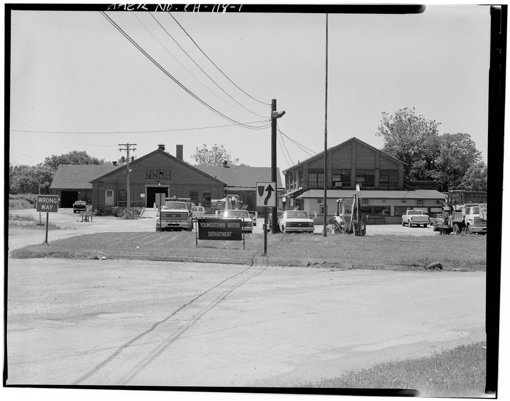
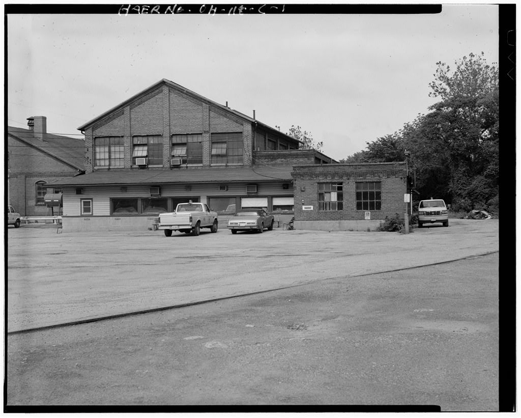
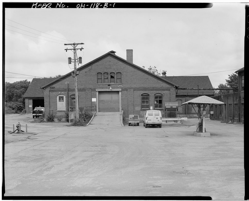
OH-118-A (Page 7) Post World War II Younqstown City Water Works Pump House Use From the mid to the early the pump house was used by the Youngstown City Police Department as a shooting range. 20 During this time, the boiler room was used as a storage facility for trucks by the Youngstown City Sanitary District. The pump house was also used as a general storage facility by the Youngstown City Water Department. 21 In September of the smokestack was removed from the exterior of the structure. 22 Contemporary Use of the Younqstown City Water Works Pump House From the early to the present the pump house has been used primarily as a storage facility by the Youngstown City Water Department, in the abandoned pump house was considered to anchor the Spring Common Riverfront Park.
However, by it was determined that the pump house should undergo massive reconstruction to become an office complex for municipal use. 20 Randall Wellington, former Youngstown City Chief of Police. Interview by Amy Clapsadle. Youngstown, OH. 30 April 21 Gene Leson. Interview by Erin Pogany. Youngstown, OH. 14 April 22 The Youngstown Vindicator, 9 September p. 13, col. 2. YOUNGSTOWN CITY WATER WORKS PUMP HOUSE HAERNo. OH-118-A (Page 8) Sources of Information/Bibliography A. Engineering Drawings Drawings in the collection of the Youngstown City Water Department January. Youngstown Water Works, Plan of Pumping Station Showing Location of' Pumps, Youngstown City Water Works. One Sheet. January. Proposed New Pumping Station (Primary Facade), Division of Water Works, Youngstown, Ohio. One Sheet.
February. Proposed New Pumping Station (North Side of Pumping Station), Division of Water Works, Youngstown,. Ohio. One Sheet. January. Proposed New Pumping Station (West Side-Double Doors), Divisionof Water Works, Youngstown, Ohio. One Sheet. December, revised Proposed New Pumping Station (Interior Pump Pit- Balcony Floor), Division of Water Works, Youngstown, Ohio. One Sheet. B. Interviews Eugene Leson, interviewed by Erin Pogany, Younstown, Ohio, 14 April Randall Wellington, former Youngstown City Police Chief, interviewed by Amy Clapsadle, Youngstown, Ohio, 30 April.1997. C. Bibliography Primary and unpublished sources: City Water Works Department, A Souvenier of Opening Day, May Howard C. Aley Collection, Mahoning Valley Historical Society.
Sanborn Maps, Secondary and published sources Books Allcut, E. A.; An Introduction to Heat Engines; University of Toronto Press; Toronto, Canada, Babbitt, Harold & Doland, James; Water Supply Engineen'ng, Morgran Hill Book Company, New York, New York, YOUNGSTOWN CITY WATER WORKS PUMP HOUSE HAERNo.OH-118-A (Page 9) Butler, Joseph G. History of Younstown and the Mahoning Valley Ohio Volume I, Chicago: American Historical Society, Daugherty, R. L, CerntrifugalPumps, McGraw-Hill Book Company, First Edition, New York, New York, Newspapers The Youngstown Vindicator, February and September m
 Block
Block