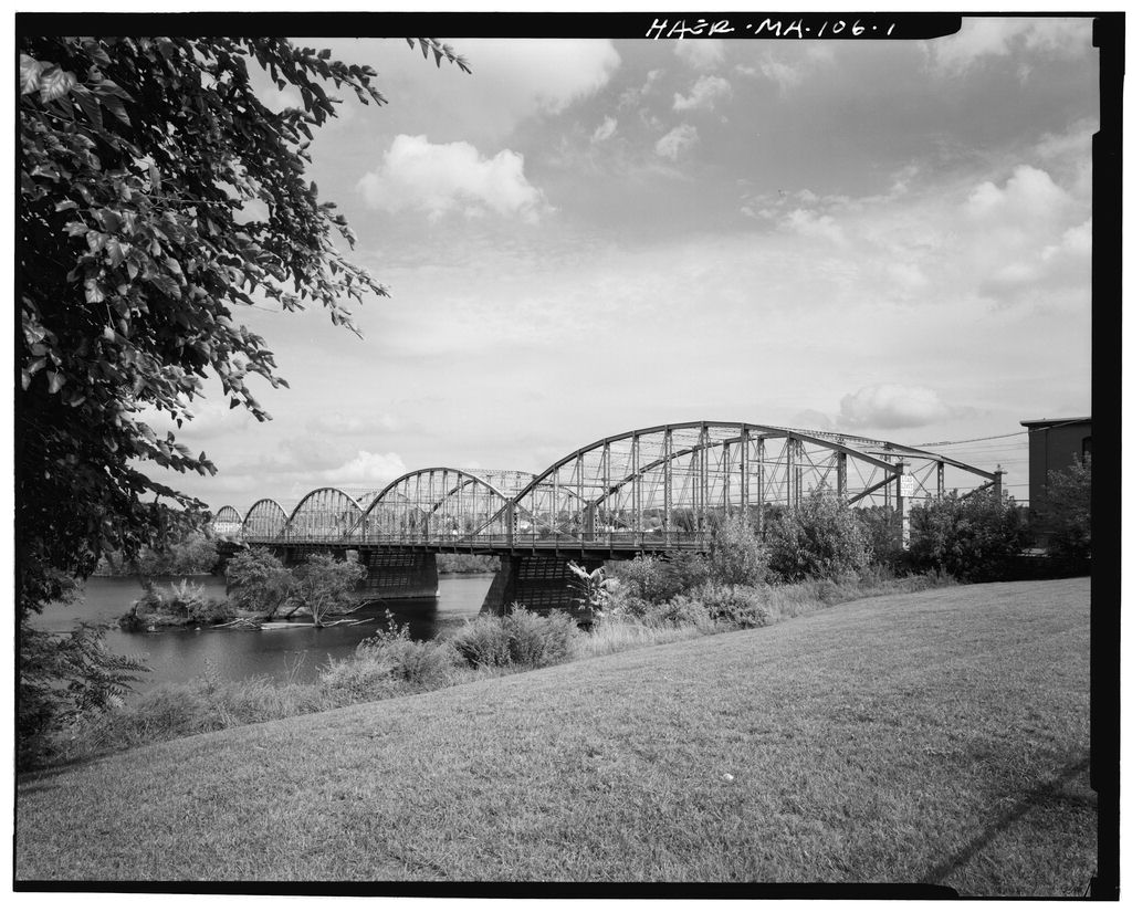
Documentation of the Aiken Street Bridge is part of the Massachusetts Historic Bridge Recording Project, conducted during the summer of under the co-sponsorship of HABS/HAER and the Massachusetts Department of Public Works, in cooperation with the Massachusetts Historical Commission. John Healey, HAER Historian, August AIKEN STREET BRIDGE (OULETTE BRIDGE) HAER No. MA-106 (page 2) Description The Aiken Street Bridge (renamed the Joseph R. Ouelette Bridge in in honor of a Lowell soldier killed in the Korean War) spans the Merriraack River on Aiken Street in the City of Lowell, Massachusetts. It is the longest lenticular bridge surviving in the United States, and is the only remaining example having more than three spans.
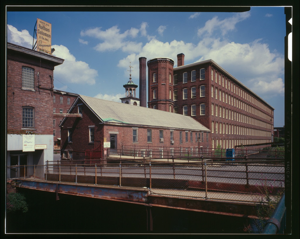
It is also the second oldest of the eight lenticular bridges under Massachusetts Department of Public Works purview.1 The Aiken Street Bridge lies immediately to the northeast of Lowell's textile manufacturing complexes, and the view southeastward, towards the Central Street Bridge, is dominated by the city's "Mile of Mills," flanking the city shore. The bridge was built by the Corrugated Metal Company of East Berlin, Connecticut between and The five-span, 675-foot structure exhibits the characteristic lenticular (pumpkinseed) truss form, for which this company was famed. The spans are all identical through trusses, their length is (center to center of endposts), the height and the width is (center to center of truss).
Two 7-foot sidewalks are carried on outriggers extending beyond the truss center line. Each truss has eleven panels measuring long. All structural components are of wrought iron. The upper chord is a built-up member in the form of an inverted trough; the lower chord is paired, wrought-iron eyebars. The verticals and "floor line chord" are built-up latticed members. The diagonals and counter diagonals are wrought-iron rods. The floor beams are built up of plates and angles, however the timber deck system has been replaced by a steel grid. The spans are supported on two abutments and four piers. The masonry work is all executed in cut and dressed granite blocks, and the piers have inclined cutwaters on their upstream faces. The deck lies some 25' above average water levels.
The principal chords of the lenticular truss are characterized by a polygonal upper chord and a catenary suspension bottom chord. Both chords converge to share a common pin connection at the top of terminal endposts. A system of latticed girders below the deck is not a principal chord member, although it functions as a chord for the lower lateral wind bracing system. The upper chord is made of three plates and four angles in the form of an inverted trough. The top plate is and the side plates are exterior "L" rollings link the components. A single lacing system connects the angles at the bottom of the section. The chords were apparently factory- riveted into lengths corresponding to about two panel widths.
The factory- riveted chord splices are located at the points where the chord angle changes, that is at the panel points. The splice is effected by two internal side gusset plates, and one exterior top plate. The shop riveting of this joint permitted the precision shop boring of the 4H-inch pin at the point of angle change in the chord (i.e. the center of the joint). The field riveting of the shop-fabricated units occurred in mid-panel, and that process is represented by the gussetted splices at those locations. The riveting of the chord plates is on a 6-inch pitch for most of the length of any one unit, but Increases to a 3-inch pitch as the panel point is approached. The chord units retain a uniform cross section across the entire truss span. AIKEN STREET BRIDGE (OULETTE BRIDGE) HAER No.
MA.-106 (page 3) The bottom chord is comprised of four sets of die-forged eyebars, As the panel lengths remain constant the length of the eyebars has to vary to accommodate the curvature of the chord. The eyes are forged to accommodate 44" pins at the panel points. Both chords are pinned commonly to the head of the endpost, the pin diameter being 5 *n. The post is and is made of three plates and four angles in the form of an inverted trough, with lacing on the inward-facing side. Immediately below the pin connection a solid plate is substituted in place of the lacing. The top of the endpost is capped by a decorative pyramidal casting featuring molded margins, and small half-spherical finial.
The base of the endpost terminates In a saddle by which the end post is pinned to the bearing shope. The connecting pin is of 4V' diameter. The shoe is comprised of a riveted fabrication, which at the rolling end incorporates a nest of nine rollers running on a bed plate. The endpost base pin also serves to connect the end floor girder and lower lateral members. The web members comprise of verticals, diagonals and counter diagonals with all connections made by pins. The dimensions of any one type of member vary according to its position in the span. The verticals are built-up girders. The flanges are paired angles, while the web is an intersecting lacing. The lacing bars are riveted between the inner faces of the "L" rollings.
The flange width of the verticals varies, the outer-most vertical has a flange of the width of the second vertical is the three verticals to the center line all have flanges of There are also subtle changes in the spacing of the lattice work within the verticals. Between posts the average pitch of the lattice work increases towards the central verticals. Within posts the pitch of the lattice varies in a complex fashion. The common point of pitch change in all verticals is the point of intersection of the longitudinal mid truss rods. Above this point the pitch of the lattice decreases.
However, in those verticals which support intermediate overhead transverse brace girders (#5 and #3) the pitch of the lattice above the brace girder increases, to be greater than that in the lower section of the vertical. The verticals terminate in reinforced saddles where the joints with both upper, and lower chords are made by 4k" pins. The diagonals, called "brace rods" by the patent holder, are paired and made of loop-welded wrought rod of various sections. Diagonals and counter diagonals are absent in the first panel. The inwardly-sloping diagonals generally increase in diameter towards the central panel. In the second panel they are of 1W diameter, and they increase successively through 1%" , 2", to in the fifth panel, however, they decrease to 2" in the central panel.
The counter diagonals are of more uniform diameter, except those in the center and second panels, which correspond to the dimensions of the diagonals in those panels, they are of 1%" rod. All diagonals and counter diagonals may be adjusted by turnbuckles. Where threaded to accept the turnbuckles, the rod is of greater diameter, such that the depth of the thread does not reduce the effective diameter of the rod. Both diagonal and counter diagonals are pin connected at their ends via the main chord pins. A mid-height longitudinal stiffening system links the verticals. It comprises of twin horizontal rods which are threaded and fixed by lock nuts to plates riveted within the web of the verticals.
In the penultimate panel the rods are inclined upwards to be AIKEN STREET BRIDGE (OULETTE BRIDGE) HAER No. MA-106 (page 4) fastened to the upper chord pin at the first panel point. The deck is hung from the lower chord pins. The suspension system is comprised of a I%"x21n" bar that is bent and doubled about the center of the lower chord pin to form a suspension members. The parallel forks of the suspension member pass to either side of the web of the transverse beam, passing through the lower flange of the beam, to hold the beam in place by a suspension plate. The plate passes between the threaded ends of the two forks of the suspension member, and is held in place by nuts. The floor beam is a built-up plate girder. The upper and lower flanges are formed from angles.
The beam tapers from 34" at the center to 22" at the point of suspension. The beams extend beyond this point to support cantilevered sidewalks. William Douglas's first-patent "floor girders" stiffen the floor beams longitudinally, and each is comprised of standardized single latticed struts made up in a similar fashion to the verticals. Each is riveted to shelf angles attached to the floor beams. A lower lateral system of rods is attached within the same fabrication. The threaded ends of the rod pass through an iron strap riveted to the floor beam, and are fastened by a nut. The gauge of the rod varies, decreasing in diameter towards the center panel. The original timber deck has been replaced with steel stringers and a steel grid deck.
The upper lateral system comprises of three elements: transverse struts, cross-braces, and longitudinal stiffening rods. All upper panel points are linked by laced transverse struts. Alternate verticals have an additional lateral strut at two-thirds height. The upper lateral struts are and the lower struts 7H" in width. They are riveted to shelf angles on the verticals. Where there are two lateral struts they are connected by sway bracing (intersecting diagonal rods pin bolted to fillet plates at the extremities of the beams, and adjusted by turnbuckles). The upper lateral cross-bracing is made of rods, the loop-welded ends of which are connected to the inner ends of the top chord pins. Each rod is adjustable by means of a turnbuckle, similar to those of the truss diagonals.
The upper lateral system features a longitudinal twin rod stiffening system, which is analogous to the mid-height longitudinal system of the trusses. The twin rods pass through, and are fixed to, the upper lateral struts by lock nuts. Above the first panel the rods divide by means of a ring connection, to be led to the upper chord beside the portal braces. The lower longitudinal rod and the upper diagonals are clamped together by plates at their points of intersection. Latticed portal bracing is provided between the portal strut and the end posts. Twin sidewalks are provided outside both trusses. Built on outriggers to the floor beams, they are contemporaneous with the main structure.
They feature lattice railings, the points of intersection being clamped by cast plate displaying a rosette motif.2 Lenticular Trusses and the Corrugated Metal Company Famed for the production of the lenticular truss the Corrugated Metal Company (which became the Berlin Iron Bridge Company in had the exclusive production rights to William 0. Douglas's patented "Elliptical Truss Bridge." William Douglas's patent of (see appendix) sought to "improve AIKEN STREET BRIDGE (OULETTE BRIDGE) HAER No.
MA-106 (page 5) the efficiency of truss bridges by combining, as far as possible the maximum strength for the minimum cost." The essential feature was that "the thrust of the upper chord was resisted by the pull of the lower chord," and to this end he combined "various parts forming an elliptical truss." The truss was composed of a "compressive chord, and an extensive chord, firmly secured at their ends, [and] with struts and diagonals between them." The struts were vertical compressive members, and the patent drawings show only one set of diagonals, which are outwardly inclined, though they intersect in the center panel.
Douglas saw the function of the components thus, "the struts, and the diagonals bind the truss together, and transfer the strains towards the farthest point of support for them, while the chords transfer the greatest strain from the point to the nearest point of support." Douglas claimed two "elliptical" truss profiles; the "parabolic" form, in which the angle of the chords changed at every panel point; and the "hipped" form, in which the chords were inclined at constant angle, about the parallel chords of the center of the span. The style selected could be "chosen to suit circumstances and taste." Clearly the hipped from was seen as being a less pure, though more easily constructed, alternative.
Douglas's patent also claimed various deck systems namely a deck truss, a half-deck truss, a through truss, and a pony truss. The latter utilized a pair of longitudinal "floor girders", suspended from the upper chord panel points by means of iron rods, to carry the floor system. For longer spans, Douglas offered the alternative arrangement of securing the suspension rods to the lower chord pins. Douglas did not necessarily envisage the structure being built exclusively of iron, neither did he specify fastenings, though he thought it "preferable" to employ pins "after the well known Pratt system."3 William 0. Douglas was born in at Cortland, New York State. At the age of 20 he entered West Point Military Academy, but his studies were curtailted by the Civil War.
By he was on active service as an infantry officer, and it was from this position that he was disabled from active service. He left the army in to become a partner in a wholesale hardware business. In he "sold his interest in this business to engage in the bridge engineering and construction." In having been granted his patent, W.O. Douglas joined the Corrugated Metal Company either granting them exclusive production rights for his bridge, or selling them the patent outright. The precise relations between Douglas and the company is uncertain. Contemporary evidence suggests that he was employed both in a capacity akin to Superintendent of Works, and as a "Special Agent" in procuring contracts. The drawings accompanying Douglas's second patent of (see HAER Nos.
MA-105 andMA-109), are indicative of his close affiliation with the company, being in every detail representative of Berlin Iron Bridge Company (the successor to the Corrugated Metal Company) engineering practice.** The potential advantages of the lenticular form had been recognized for some time prior to Douglas being granted his patent. First, the parabolic form minimized the stresses in the chord members, affecting a saving of material in those members. Second, the balance of forces between chord members was such that the forces acting on the endposts were entirely vertical, as such abutments did not have to be built to withstand any significant horizontal thrust. The form was developed in France during the AIKEN STREET BRIDGE (OULETTE BRIDGE) HAER No.
MA-106 (page 6) and evolved in Germany and Britain during the Brunei's spans in England and Wales, perhaps representing the apotheosis of the form. These spans were conceived and built in the European tradition, being specifically engineered for a particular crossing, and. constructed over a number of years. Several American patents for lenticular trusses pre-date Douglas's. Edwin Stanley, and Horace Hervey and Robert Osborne having been granted patents in and respectively. It is unclear whether Douglas's design Is derivative of these patents or was the product of original thought.5 As originally patented, the design shows none of the sophisticated nuances evident in the Aiken Street Bridge, although the general truss configuration is similar.
In the patented design the sole set of diagonals slope outward. The reason for this reversal of slope of the principal diagonals is unclear. Douglas's explanation apparently looks back to the designs of Fink and Bollman, explaining their function as one of transferring the load to the farthest abutment, rather than countering shearing force in the panel. The design appears to be one born of the intuitive school of engineering, tempered by exposure to some basic formal engineering.6 Originating as a company involved in the tin-smithing trades, the predecessors to the Corrugated Metal Company became involved in the manufacture of corrugated iron roofing materials.
At first known as American Corrugated Iron, it became the Metallic Corrugated Shingle Company in and after the Corrugated Metal Company. By the company, with its small factory beside the Mattabesett River, was in deep financial difficulty, and was taken over by Wilcox. Wilcox's role was pivotal in securing the future of the company. Almost immediately he purchased the rights to Douglas's patent, and began to use the plant to produce the lenticular trusses that would soon become the hallmark of his company. At the time, the company had only twenty employees. The first bridges that were built were reported to be "crude affairs," perhaps confirming the limited nature of Douglas's engineering skills.7 Soon after this, Wilcox engaged the Yale-educated Charles M.
Jarvis as Engineer and Superintendent. It would seem that the refinement of the design was the product of Jarvis's intellect and formal training. His first modification was a change in chord profile such that the panel points lay on a true parabola. It seems likely that at an early date he would also have modified Douglas's diagonal geometry, reversing the inclination of the principle diagonals. By the early it would seem that Jarvis had refined Douglas's patent further, both by the introduction of new components, but perhaps more importantly by the detailed proportioning of members to reflect the strain patterns in the structure.
Documentation shows that by the company made estimate for new contracts upon the basis of precise calculation of the strains within the proposed structure, components being specified accordingly.8 The detailed understanding of the lenticular forms mechanical behavior is demonstrated by the structural elements in the Aiken Street Bridge. The uniformity in cross section of upper and lower chords may be explained in terms of the very small increases in strain calculated to occur in these members. By ensuring that the chords followed a true parabola, Jarvis reduced AIKEN STREET BRIDGE (OULETTE BRIDGE) HAER No. MA-106 (page 7) the differential strain in these members to a minimum.
The verticals are proportioned so their length corresponds to the variations in the moments calculated to occur in the structure. The sophisticated changes in the design of the verticals reflects the halving of the strains in the shorter columns. A set of mid height longitudinal stiffening rods have been introduced. In addition to tying the verticals, it would appear that by dividing the vertical they affected an increase in the compressive load bearing capacity of this member. The change in pitch of the latticing above the longitudinal rods apparently indicates a perception of reduced compressive strains in the vertical above the point of intersection. The dimensioning of the diagonals, and counter diagonals accurately reflects the tensile loads calculated to occur within the panels.
It appears that Jarvis perceived how small changes in upper chord angle could produce proportionately large increases in shear within the panel. The increase in diagonal dimensions to either side of the central panel reflects the increase in shear caused by the chord beginning to be angled to form a parabola.
Their subsequent diminution reflects a decrease in the tensile strains as panel height increasing in diameter towards the center, whilst the upper lateral struts have been stiffened by a longitudinal rod system, analogous in form and function to that of the trusses.9 Under the direction of Wilcox the company prospered, and the number of employees increased to 500 by In that year, the company's $2 million annual turnover was to attract the attention of those wishing to create the American Bridge Company, and in that year it was absorbed into this combine. Wilcox's direction was apparently crucial to the company's transformation into one of the country's foremost bridge manufacturers.
The decisions to acquire exclusive production rights to Douglas's patent, refine the design by employing a formally-trained engineer, produce this design almost exclusively, concentrate only on the production of highway bridges, and market the product aggressively, combined to ensure success. The design was inherently economical in chord materials, while the abutments were only required to resist vertical loads. The application of formal engineering theory to the design achieved further economies of material. Specialization in the lenticular form conferred economies through volume of production. This was particularly important as the parabolic form could not be entirely standardized.
Local History The City of Lowell grew along the Merrimack River about the portage around the Pawtucket Falls. The river was first bridged in by the Pawtucket Bridge, to be followed by the Central Street Bridge of At the time when the river was first bridged, the only settlement was a cluster of farmsteads on the south bank about the bridge head, known as East Chelmsford. Central Bridge was built just above the confluence of the Concord River. Its construction immediately pre-dates the rapid evolution of Lowell into a major center of textile production. The Merrimack Manufacturing Company was founded in and the capital applied by "The Boston Associates" resulted dynamic growth.
Within fourteen years, the settlement supporting a population of had been incorporated into a city.10 AIKEN STREET BRIDGE (OULETTE BRIDGE) HAER No. MA-106 (page 8) By the pressure was developing for another crossing to be provided thus "relieving the crowded parts of the city and opening up new territory." The precise location of the bridge was to grow to become a matter of local controversy, involving accusations of interested parties taking steps to ensure an outcome most favorable to themselves. A "Joint Special Committee on Constructing a New Bridge over the Merrimack River" was formed to consider the various sites.
Four crossing points were proposed: Major Emery, of the Locks and Canal Company, wished to see the crossing at Cheever Street; Thomas Nesmith proposed a crossing at Aiken Street; Tilden Street was the favored bridging point of the Merrimack Corporation and Charles Callahan; and Richardson and McEvoy petitioned for a bridge near Perkins Street. The Cheever Street crossing would have been out of the town center, to the west of the Pawtucket Falls close to the present Moody Street Bridge. The river at this was at this point relatively narrow. The Aiken Street crossing would bridge the river farther down stream on the immediate periphery of the town's industrial center. The crossing point was however, the longest proposed, spanning both the Main Channel and the North Channel.
The Tilden Street crossing was most convenient to the city center, and provided immediate access to the settlement of Centralville on the opposite shore. Although the river had narrowed somewhat at this point, the city banks were already occupied by mill operators who required compensation payments. The Bridge Committee met on June 13, and agreed to seek estimates for bridging the river.11 On July 14, the Middlesex County Commissioners heard witnesses in favor of the various schemes. The cases for the Emery proposal (Cheever Street), and the Nesmith proposal (Aiken Street) were apparently well represented. The crucial argument seems to have hinged on the likely increase in property prices on the undeveloped lands to be most immediately served by the new bridges.
The figures quoted for Lowell's two existing crossings suggested that the Aiken Street Bridge would generate a greater increase in land values within the city.12 The county could apparently make no decision until the city had made its own recommendations. To this end, the Special Committee received estimates from two engineers of the New York Bridge Company for the various crossings. The Cheever Street Bridge was the cheapest at an estimated cost of for a 30-foot roadway carried by two 165-foot spans, and requiring one pier and two abutments. The Tilden Street proposal crossing was estimated to have required for a 30-foot roadway carried by four 167-foot spans, requiring three piers and two abutments. The Aiken Street proposal was the most expensive.
The estimates for a 30-foot wide bridge of five 163-foot spans, requiring four piers and two abutments was No estimates were sought for the Perkins Street crossing.13 On August 26 the Special Committee met once more. They compared the estimates of the consulting engineer Munroe (of the New York Bridge Co.?), and the very similar figures put forward by City Engineer Shipman. It was at this meeting that the committee was informed of the considerable additional cost of pushing a bridge through the developed lands at Tilden Street, being the estimated cost of "land damages."14 Matters concerning the bridging became quiescent, presumably as interested parties took stock of their positions. In November a fourth potential bridging point was suggested to the City Council.
On November 8, "ten of the largest corporate bodies in AIKEN STREET BRIDGE (OULETTE BRIDGE) HAER No. MA-106 (page 9) the city," together with various individuals, proposed a crossing at Perkins Street. Little more seems to have been done regarding this proposal. Aiken Street Bridge The Special Committee convened a bridge hearing on Septmeber 12, The representations made marked a significant realignment of corporate support, greatly favoring the bridge at Aiken Street.16 The Merrimack Corporation had abandoned its support for the Tilden Street crossing, and joined the Lawrence, Middlesex, Tremont & Suffolk, Lowell Bleachery, Lowell Carpet, Massachusetts, Boott Hamilton and Appleton Corporations in favor of the Aiken Street Bridge.
These petitioners favored the bridge as "it benefitted the greatest number at the least cost, and was the most useful." Those still in favor of Tilden Street were to quote the difficult foundation conditions "a solid foundation not found at and the length of (including bridging the North Channel) as obstacles to the successful completion of the Aiken Street Bridge. The city attempted to resolve matters by asking those in wards affected by the proposals to express their preference for crossings at Aiken, Tilden or Cheever Streets.
The election was held on October 13, and Aiken Street was overwhelmingly the favored site for the new crossing, voting for that site, 635 for Tilden Street, and 332 for Cheever Street.17 The democratic ideals of the City Fathers were, however, compromised by those who sought particular advantage.
The local press reported that Charles Callahan asked "that if you were in favor of the common working man [then] Clam Chowder and free beer [would be offered to all who attended a meeting] for the purposes of making arrangements in favor of a bridge at Tilden Street."18 While the rather more wealthy corporate proponents of the Aiken Street Bridge were accused of paying in rum in order to catch voters of the Aiken Street Bridge."19 Following the election, a special meeting of the City Council was called for October 17, at which it was voted to borrow for the City Treasurer for the construction of a bridge at Aiken Street.20 The Treasurer arranged finance through notes to the value of drawn on the Lowell Institution for Savings.
Acting upon the vote of this meeting, the city tendered for bids from the bridge companies. Doubtless having heard of the experiences of others when dealing with bridge contractors, the city took the (then somewhat unusual) step of employing an independent consulting engineer.
His contribution extended beyond offering advice on the bids, to include the draughting of "minute specifications," which allowed "an individual company to indicate the general designs on which they proposed to build the work, but having allowed so much allowed no more." Within any bridge company's design the structure had to "conform in every detail or connection to the rules laid down", the rules being "so minute that nor a pin, bar, bolt, rivet, or any other connection can be overlooked".21 The city appointed John C. Cheney of Boston as consulting engineer, and asked him to draw up the specifications, review the designs of those bidding, and make recommendations to the bridge committee on his findings. For this work, Cheney was paid a fee of AIKEN STREET BRIDGE (OULETTE BRIDGE) HAER No.
MA-106 (page 10) In undertaking this work he was not to be privy to the quotations given by the bridge companies. There was a delay in tendering as the City Solicitor attempted to define "the bed and banks of the river". On the north bank, the engineer to the Proprietors of Locks and Canals, Major Emery would not permit the infilling of the North Channel. In the expectation of being granted such permission, the city had only requested bids for a bridge terminating on Long Island.
Subsequently, companies were apparently asked to bid for both the "long bridge" and the "shorter bridge."24 It was finally resolved to bridge the North Channel by a timber trestle, the city clearly expecting that once "Emery's Last Stand" had been forgotten, consent would be given to the infilling of the channel.25 On March 23, the Special Bridge Committee revealed the bids, and voted to award the contract to the Corrugated Metal Company, In descending order the bids were: with a completion time of seven months, from the Pennsylvania Bridge Works Co,; and twelve month delivery, from Mount Vernon Bridge Company of Ohio; from the King Iron Company of Cleveland; and a six month completion date, from the Boston Bridge Works; four bids from the Corrugated Metal Company, (plan A), (plan C) , (plan D) , and (plan B) , each with a four-month completion date (the committee accepted the bid); and a five- month completion time from the Massillon Bridge Company of Ohio; and a seven-month completion time, from the Wrought Iron Bridge Company of Ohio; and, and an eight-month completion time, from Whittah & Powers of Hudson, New York.26 The vote of the Bridge Committee was in complete contradiction to the recommendations made to it by both City Engineer Evans and Consulting Engineer Cheney.
Cheney's first choice was the design provided by Clarke Reeves & Co. of Phoenixville, He expressed satisfaction with this design as "first class", while he thought those of the Boston Bridge Works and the Wrought Iron Bridge Company were "probably first class". Of the remainder, Cheney was said to be "particularly opposed to the Corrugated [Metal] Company's Bridge". Evans, being privy to the quotations favored the Wrought Iron Bridge Company's bridge.
The quotations for the recommended bridges were such that Cheney's favored bridge was more, and Evans's less, than that selected by the Bridge Committee.27 In spite of the obvious disdain of the Mayor, the contract for the bridge was signed in the presence of the Corrugated Metal Company's Chairman, Wilcox, on March The letting of the contract unleashed a barrage of invectives and innuendos concerning the suitability of the lenticular design, the practices of the Corrugated Metal Company's representatives, and the response of certain Bridge Committee members to these representations, particularly with regard to their dismissal of the advice of the city's Consulting Engineer.29 George Vose, a consulting engineer who had "fought long and hard against reckless bridge building," commented, "we have had cases enough where public officers have been imposed upon by bridge makers, but I do not recollect hearing before of a city government deliberately employing experts to examine different plans, and then setting all the expert opinion at defiance, and selecting the very plan which was reported on unfavorably."0 AIKEN STREET BRIDGE (OULETTE BRIDGE) HAER No.
MA-106 (page 11) From March 1, when the bids for the bridge were opened, until the contract was signed, the Corrugated Metal Company was said to have been "Nobly Represented."31 In contrast to all the other bidding companies, the Corrugated Metal Company appears to have undertaken extensive lobbying of the bridge committee members, and also to have approached the city's consulting engineer. On March 25, The Lowell Sun reported that the Corrugated Metal Company's three representatives "have devoted weeks to staying in Lowell visiting the different members of the Bridge Committee." The representatives were identified as Towne the Company's agent, Mr. Jarvis the Company's Engineer, and Mr. Douglas the Company's Special Representative" (presumably W.O. Douglas himself).
The three had apparently been in the city since the day that the bids were opened.32 The Lowell Sun conducted an investigation into their activities, and reported: We have statements before us in black and white, [that indicated] Mr. Towne acting as agent for the Corrugated Metal Company offered a well known civil engineer, employed in a public capacity (alluding to Cheney) a certain sura of money as a bribe to have him report favorably on this company's bridge. The newspaper went on to suggest that those members of the Bridge Committee who voted for the Corrugated Company might have accepted similar inducements!
Notwithstanding the above accusations, the Corrugated Metal Company appears to have applied itself rather more diligently to the provision of detailed "working-up" of its proposals, and unlike any of the other companies offered four different plans all individually costed. The Lowell Sun reported that "some of the bidders did not send in very detailed specifications, and they had nobody here to explain things. The Corrugated Metal Company were very explicit in their specifications, and had representatives here to answer all questions."33 The precise details of the four designs offered by the Corrugated Company are not given, although it appears they were not confined exclusively to the lenticular form.
Speaking of the Corrugated Metal Company's representatives, the Mayor said that "he was glad to get all the information he could on the subject ... and that they (the company's representatives) explained the difference between the parabolic truss and the Pratt truss. They were prepared to furnish the Pratt truss." The Mayor also alludes to the differences between designs A and B in which "the posts and diagonals of plan B were not so strong as those in plan A, but an iron cord(sic) attached to the truss was supposed to make up the deficiency." The presence of both Jarvis and Douglas at Lowell suggests how important such a large and prestigious contract was to a company trying to establish itself and its product within the highly competitive bridge fabrication market.
The correspondence generated by the award of the contract to Wilcox's Company served to demonstrate how difficult it was for a newcomer with a new product to enter into the field.3* The recurrent themes were those of lack of experience and the unproven qualities of the design. Of the former, Vose warned against "accepting a bridge from a concern of limited experience" while the two Ohio companies placed great emphasis on their experience. The integrity and durability of the new lenticular form was called into question. AIKEN STREET BRIDGE (OULETTE BRIDGE) HAER No.
MA-106 (page 12) Vose called it "a questionable bridge for a large price"; Cheney condemned it as being "decidedly faulty, every other post being weak"; and City Engineer Evans had "devised such improvements as will keep the bridge from falling to bits." On April 20 the Special Bridge Committee met to award the contracts for the masonry work. The mansory work was apparently delayed as the original contractor was not able to accept the work. The contract was let to Trumball & Cheney, who quoted for the building of the four piers and two abutments.
The highest bid of was from P&J O'Hearn, who was to be involved in fulfilling part of the contract.35 Both the piers and abutments were to be founded on a 24"-thick concrete raft laid on 12"~diameter spruce piles, to be driven on 36" centers until firm foundations were encountered. At their base the pier foundations were to be long and 13 wide.36 On the day the contract was awarded, Trumball & Cheney's "boats arrived at site," and by April 28 the City Engineering Department was surveying in the bridge line.
The general procedure of construction involved the construction of a cofferdam using an "engine" and derrick; the area within the cofferdam was then pumped out; once sufficiently excavation would begin for the foundations; when excavation was complete the piles would be driven; the concrete raft would then be cast, and the masonry work begun. All the above work was the responsibility of Trumball & Cheney. When the masonry work was ready for the superstructure the Corrugated Metal Company would erect their timber falsework between the piers, and when complete begin to assemble the ironwork. Only when the entire structure was completed would the cofferdams be removed. It is difficult to deduce the precise progress of works, though it is apparent that construction began at the south abutment.
The initial works were flooded when on May 31 the "water rose over the coffer dam," and it would appear that the dam was breached as Trumball & Cheney began to drive piles for the cofferdam. By June 12 excavation was underway, and in spite of encountering springs in the gravels they were completed within three or four days, and on June 15 the "pile drive was arranged," to begin work two days later. Only five of the 132 piles had been driven when the cofferdam was again overtopped by the waters of a cloudburst on May 18.
By June 22, twenty- one piles were down, but three days later concreting was taking place "to counter spring waters." Further progress on this abutment is difficult to ascertain though It was known to have been completed by November 4, Progress on the piers is more easily traced in the City Engineer's notes. The piers were constructed between July and November. Information contained in the City Engineer's notebook suggests that it took about one month to construct the cofferdams, about one week to excavate the foundations (where necessary), a week to ten days to drive the foundation piles, a week for the puring and setting of conrete, followed by some six weeks constructing the pier stonework, or about ten weeks to build the abutment walling.
As to the labor employed, on June 12, when the contractors were experiencing difficult ground conditions at pier 1, it was noted that "14 diggers, 1 engineer, 1 foreman worked overnight through June." While on Sunday October 29 an entry notes, "Frenchmen struck for $2 a day this morning, and came back at noon on those terms." A Stapes received as AIKEN STREET BRIDGE (OULETTE BRIDGE) HAER No. MA-106 (page 13) Inspector of Masonry.38 The City Engineer's notebook reflects his diminshed role during the erection of the ironwork. There are passing entries until the date the masonry was completed, and one after that point.
On the September 1 the Corrugated Metal Company arrived on site so they could begin "works on ground." At this date none of the masonry work as ready to receive the ironwork, and it is probably that they were creating a railhead storage are for timber, and iron. There seems to have been a delay while the masonry of the south abutment, and the fist pier was completed, for it was only on October 2 that the City Engineer noted, "Corrugated Company putting up false work." On October 31 it was noted, "Corrugated company putting beams in place, they have located 4 today." More details are given four days later when the newspaper interviewed Mr. Otis, an agent of the Corrugated Metal Company.
The falsework had been erected for the first two spans, and ten floor beams were in place between the south abutment and the first pier. That week they were expecting deliveries of iron so that work could begin on the second span.
Each span was said to "about ten days to construct in good weather." Perhaps there had been delays in the delivery of the ironwork, for when quizzed on the matter, Otis replied that it "arrives as fast as wanted." Such delays seem very likely as the Corrugated Company's schedules must have been severely disrupted when flood waters swept away the staging of the bridge they were constructing at Waterbury, Connecticut.39 At this date a construction crew of sixteen was engaged by the Corrugated Metal Company, though more were said to be required "when the work was a little more advanced."40 On the November 12 a shipment arrived for the Corrugated Company, presumably the ironwork spoken of.
The following day, the Corrugated Company was noted as "erecting two derricks at end of first span." On November 18 the river was noted to be "iced over." Presumably the onset of winter considerably hindered completion of the ironwork, for in his annual address the Mayor observed that "the iron trusses are placed in position on one span."41 On February 25, It was reported that "the bridge is considerably travelled though not formally thrown open." On that date the ironwork was complete save for the railings, though the formal opening had to await the completion of the appropaches which were said "not to be In a safe condition."42 The bridge was reported to be fully opened on March 23, although there appears to have been no formal ceremony.43 The final details were complete when the Superintendent of Street Lights installed gas lighting across the span.44 Although no mention is made of testing the bridge, the treasurer's accounts contain an entry for paid to the United States for use of a testing machine.45 The Corrugated Metal Company's bridge required falsework to be erected, as only a rigid structure could be cantilevered from the piers.
Once the falsework had been completed the first stage of iron construction appears to have beens the placing of the floor beams in their correct position on top of the staging. The trusses were constructed in situ, working from the fixed end to the rolling end. A travelling overhead gantry of timber was erected on stafing to facilitate this process. Both trusses advanced simultaneously, each panel being completed, with diagonals and upper laterals before work progressed on to the next panel. AIKEN STREET BRIDGE (OULETTE BRIDGE) HAER No. MA-106 (page 14) The total expenditure for the bridge amounted to of which the Corrugated Metal Company received being withheld from the contract price as damages due to delays in completion.
The city was reported to be considering action for damages "for considerably exceeding the stipulated time,w47 however the contract was found to be "faulty" as no penalty for delay had been written within.48 The contractors for the masonry work, Trumball & Cheney, received The bridge was completed within the budget, a surplus of remaining in the account. Maintenance The subsequent history of the bridge confounds the predictions of its detractors. The trusses and floor beams remain as built, major repairs being confined to maintenance and replacement of the deck structure. In the transverse wooden stringers were replaced. In the deck timbers were renewed in yellow pine. In the north abutment was repaired and faced in concrete.
By the deck was reported to be in poor condition, and in the following year steel stringers and a steel grid floor were installed. The decking was overhauled and modified in At the same time the original expansion rollers were replaced with self-lubricating bronze plate bearings.49 AIKEN STREET BRIDGE (OULETTE BRIDGE) HAER No. MA-106 (page 15) UNITED STATES PATENT OFFICE. I\ WILLIAM O. DOUGLAS, OF BIKGHAMTON, NEW YORK. IMPROVEMENT IN TRUS3-BRIDQES. " *': Specification fuming part of Utton Tfttoat No. , <UleJ April ; application tiled <iS3 March 38, - -AS * 1 To ail w/iom tt may concern; tho lower chord G at the foot of the struts. Be it kuewn that I, WILLIAM O. DOWLAS.
At the center of the bridgo, where tho diag- of Binghamton, in tho county of Broomo ami onals cross each other, both their upper aud State of Now York, havo invoutod certain now lower cuds aro fastened to tho respective nnd useful Improvements in Trus3-Bridgcs; chords by pins S, as shown in Figs. 1 and 3; and I <lo hereby dccluro the following to bo a or tlio trv.sRoa may be, aud preferably aro for full and exact description of tho same, refer- long spans, conuccted by pins throughout, aftor ence being bail to tho accompanying drawing, tho well-known details of tho Tratt trass, as forming part of tins specification, in which now usually employed. Figure 1 ia a sido elevation of a through- Tho struts 15 and diagonals D bid tho truss ! bridge; Vic.
2, a sido elevation of a dock- together, and transfer the strain* toward tho . ;.) bridge; Fig. 3, a sido elevation of a Hiviug- farthest point of support from thorn, whilo the 1 t vJ 1 K>| bridge; Fig. 4, a sido elevntion of a bridge chords B G trausfer the greatest strain from with tho roadway through the center of the tho samo point to the nearest point of support trims; and Fie, 5 is a Hour plan of tho bridge, or abutment, all constructed iu accord unco witb uiy inven- tion. G is tho floor-girder to support tho roadway, having transverse Joist, mid either extends to 1 <s Similar letters of reforonce >n tho accompa- the abutments below tho chord C, as in Fig. 1, nying drawings denote tho (j.i-nc parts. or above tho chord B, as in Fig.
'J,or through My invention has for iu object to improve tho center between the two chords B C, as iu tho construction uiidcflleioncy of truss bridges Fig. 4, or below the lower chord U, but uusup- 3 by combining as far as )>os*ibto tho maximum ported by the abutments, as in Fig. 3. of strength with tho minimum of cost; mid In Figs. 1 and 3 tho part G and die roadway to this ond it consists, iu tho combina- are supported by rods F F, which run through tion of parts formiog on elliptical truss; and, tho chords 1) 0 and the number 0, and secondly, in tins construction of bridges with through or alongside tho struts F, being se- such trtinscs as I will now proceed to describe. en rod by nuts at tho top of the truss and be- The truss, which constitutes the ilrst part of neath the part G.
In long spans tho tic-rod my invention, is shown in tho accompanying F docs not run through to the top chord B, drawings composed of a compressivo chord, but is secured to the chord 0 at each panel- V B, and an extouaion-chord, O, firmly secured Joint, as by a plo, a saddle-plate, thread and together at their ends A, with the struts E out, or bolt-head. and diagonals or tension-rods D between them. Iu Fig. 2 the tie-rods aro similar' ~ connected The trusa thus constructed is shown in Figs. at the ton to the part G, nnd at their lower 1, 2, and 3 la hipped form, and in Fig. 4 of ends to the chord G; but iu Fig.
4 their ends parabolic form; but the genoral form ia thntof are held in the two chords aud pass through an ollipso or parnbolio ngaro, which may bo tho part G at about their centers, modified to suit circumstances or tho taste of Iu a bridgo constructed as shown in Fig. 1, tho constnicter. the member G serves to prevent the truss from In Fig*. 1, 2, 3, andv4 the thrust of tho top moving bodily endwise, being attached along chord B is resisted by the pull of tlio lowor tho center thereof to tbe chord G and to the chord 0; but ia the form shown iu Fig. 3 this bridge-seat. It also acts as part of the sway. is reversed when the ipon is open ; then tho brace system ..bown in Fig.
5, being subject pall Uupoa the upper chord, which rcsisUthe to but little tensile and compreasive strain, thrust of the lower chord. and forming no part of tbe supporting power The diagonals D are preferably arranged iu of the tmas. As a beam it carries the iloor- pairSjSithough this Is uot absolutely essential, Jolat between the tension-rods F,but ia lighter and-Are connected to the top obord B by pius In section when the floor-beams snpportiug 8. passing laterally through them and the longitudinal Joist rest npon it at or near the chord, while the lower ends art held ID saddle- rods F. For carrying Joist upon It between plates m at tlio points of their connection with such rods, It may be reinforced by % T-bax, I, * >*. AIKEN STREET BRIDGE (OULETTE BRIDGE) HAER No.
MA-106 (page 16) * *, (shown m Figs. 1, 2, 3, 4,) or otherwise in- and all compreaairQ members most be con- H*s creased iu vertical diameter sufficiently to per- atructed with a proper ratio of diameter to J " form the office of a beam to carry transverse the length, In order to properly resist com* fr- join, as shown at riebt hand of Fig. 0. preasive strain. The trasses or bridge may In Figs. 1 and 3, U H are end posts which be constructed of iron or wood, or both. ^:_ support the trusses wbeQ the roadway ia along I claim as my invention > tho bottom. They may l>e dispensed with 1. An elliptical bridge-truss consiitiug of when tho floor-line is along the top of the truss the chords B C, united at their ends, with the . or through the center,a ahowit in Figs.
2 nod struts E and diagonals D between them, sub- ^ 4, In Fig. 4 the floor-liuo is uacouQectcd with stantially aa described, for the purpose speci- \- tho truw at the oods. fied. %r Fig. 6 shows tlio different arrangment of 2. ID combination with tho elliptical truss, &. tho tJoor-joist and plaukiug the right-lmod constructed as described, the suspension or ?; ^ half having transverse joist and longitudinal tension rods F and floor-girders O, substan- jv ' planking, and the left-hand half having Ion- tially K* described, for the purpose specified. K . . gitudiual Joist and cross piankiug. This 3. In corabiuatioo with the elliptical truss, k- uro also shows tho connections between the constructed as described, the suspension or & girders G ^od the trusses to form a bridge.
tension rods F, floor-glrdera 0, and end posts The strains are oa follows: The memhem B, H, substantially as described, for the purpose EE, and H are comprossire, and the members specified. 0, D,and F are tcnsilo, oxcopting in the form 4. The combination of two or more elliptical shown In Fig. 3 for aa open span, ia which trusses, constructed as herein described, with j case tho chord B is tensile and the chord C the floor girders and Joists, and the necessary i v." comprossire,aa previously stated. The strains flooring to form a through, deck, or awing $ upon the girder O and T-bar I an slightly bridge, substantially as described. w- corepressive and tensile and transverse, ac* WILLIAM 0. DO0QLAS. ?: cordingly aatbejoisUare placed longitudinally i* . . or transversely with tho truss.
Witnesses: & All tho tensile members may be made of A. J. IjfLOES, H -" any couvonient form round, square, or flat FEED. W. SJUTH. u:-. AIKEN STREET BRIDGE (OULETTE BRIDGE) HAER No. MA-106 (page 17) 1 bf it I W. 0. DOUGLAS. Truss-Bridge. No. - , Patented AprHJ6, : AIKEN STREET BRIDGE (OULETTE BRIDGE) HAER No. MA-106 (page 18) I 8b t 2 W. 0. DOUGLAS. Truss-Bridge. No, Patented April 16, INVENTOR AIKEN STREET BRIDGE (OULETTE BRIDGE) HAER No. MA-106 (page 19) t 8h* W. 0. DOUGLAS. Truss-Bridge. No. Patented April 16, i * x W1TME3SE0 . INVENTOR 4&Lij< ZtZ -f >. /<A* ATTORNEY,?.. s AIKEN STREET BRIDGE (OULETTE BRIDGE) HAER No. MA-106 (page 20) ENDNOTES 1.
The Massachusetts Historic Bridge Recording Project documented three other lenticular truss bridges: Bardwell's Ferry Bridge at Conway/Shelbume (HAER No. MA-98), Tuttle Bridge at Lee (HAER No. MA-105) , and Blackinton Bridge at North Adams (HAER No. MA-109) . 2. Corrugated Metal Company, "Aiken Street Bridge," original drawings, Office of the City Engineer, Lowell, Massachusetts. 3. William 0. Douglas, "U.S. Patent No. April 15, 4. "William 0. Douglas," biographical sketch in Broome County Biographical Review. Broome County. New York (Boston, 5. Victor Darnell, "Lenticular Bridges From East Berlin, Connecticut," The Journal of the Society for Industrial Archeology, vol. 5, no. 1, p. 19. 6.
Professor Dan Schodek, Harvard University Graduate School of Design, personal conversation with author, July 7. Darnell. 8. See report and field file for the Bardwell's Ferry Bridge (HAER No. MA- 9. Schodek, conversation with author. 10. Growth can be traced through the following maps and plans, in the collection of the Lowell Historical Society: Hales, "Plan of Pawtucket, Chelmsford Township, B. Mather, "Lowell and Belvedere Village, and, Boynton, "City of Lowell, 11. The Lowell Sun. Lowell, Massachusetts, June 19, 12. Ibid., July 17, 13. Ibid., August 7, 14. Ibid., August 28, 15. Ibid., November 13, 16. Ibid., September 17, 17. Ibid., October 15, 18. Ibid., October 6, AIKEN STREET BRIDGE (OULETTE BRIDGE) HAER No. MA-106 (page 21) 19. Ibid., October 22, 20. Ibid., October 22, 21.
Ibid., April 1, 22. Lowell Citv Book. p. 23. Lowell Sun. March 25, 24. Ibid., April 1, 25. Ibid., March 18 and April 15, 26. Ibid., April 1, 27. Ibid.. March 25, 28. Ibid., April 1, 29. Ibid., March 25 and April 1, The Lowell Sun was particularly rigorous in pursuit of this matter, reporting bridge developments under such bylines as: "Is There Anything Crooked?, Are Our Good Citizens Being Swindled?" (March "Was the Bridge Committee Bribed?" (March and "Apparent Crookedness" (April 1) . 30. Ibid., April 8, 31. Ibid., April 1, 32. Ibid., March 25, 33. Ibid., March 25, 34. Ibid., April 1 and 8, 35. Ibid., April 22, 36. Plans for Aiken Street Bridge Piers and Abutments, Office of the City Engineer, Lowell, Massachusetts. 37. Lowell Sun. November 4, 38. Lowell Citv Book. p. 39. Lowell Sun.
September 30, 40. Ibid., November 4, AIKEN STREET BRIDGE (OULETTE BRIDGE) HAER No. MA-106 (page 22) 41. "Mayor's Address," Lowell Citv Book p. 16. 42. Lowell Sun. February 25, 43. "Report of the Superintendent of Streets," Lowell City Book. 44. "Mayor's Address," Lowell City Book. p. 30. 45. Lowell City Book. p. 46. Victor Darnell's Directory of American Bridge Building Companies. (Washington, DC: Society for Industrial Archeology, contains an illustration of a lenticular span under construction on page 57. 47. Lowell Sun. February 25, 48. "Mayor's Address," 49. Aiken Street Bridge Maintenance Records, Office of the City Engineer, Lowell, Massachusetts. AIKEN STREET BRIDGE (OULETTE BRIDGE) HAER No.
MA-106 (page 23) BIBLIOGRAPHY "Bridge Massachusetts Department of Public Works Bridge Section files, Boston. Corrugated Metal Company. "Aiken Street Bridge," original drawings, Office of the City Engineer, Lowell, Massachusetts. Corrugated Metal Company. "Contract and Specifications for the Bardwell's Ferry Bridge, (On file at the Office of the Town Clerk, Shelburne, Massachusetts; copies included in the HAER No. MA-98 field file.) Darnell, Victor. "Lenticular Bridges From East Berlin, Connecticut," Journal of the Society for Industrial Archeology, vol. 5, no. 1, pp. 19- 32. Darnell, Victor C. A Directory of American Bridge Building Companies. Occasional Publication No. 4. Washington, DC: Society for Industrial Archeology, Douglas, William O. "U.S. Patent No. April 16, Douglas, William 0.
"U.S. Patent No. April 7, The Lowell Sun. Lowell, Massachusetts, "William 0. Douglas," biographical sketch in Broome County Biographical Review. Broome County. New York. Boston,
 Block
Block