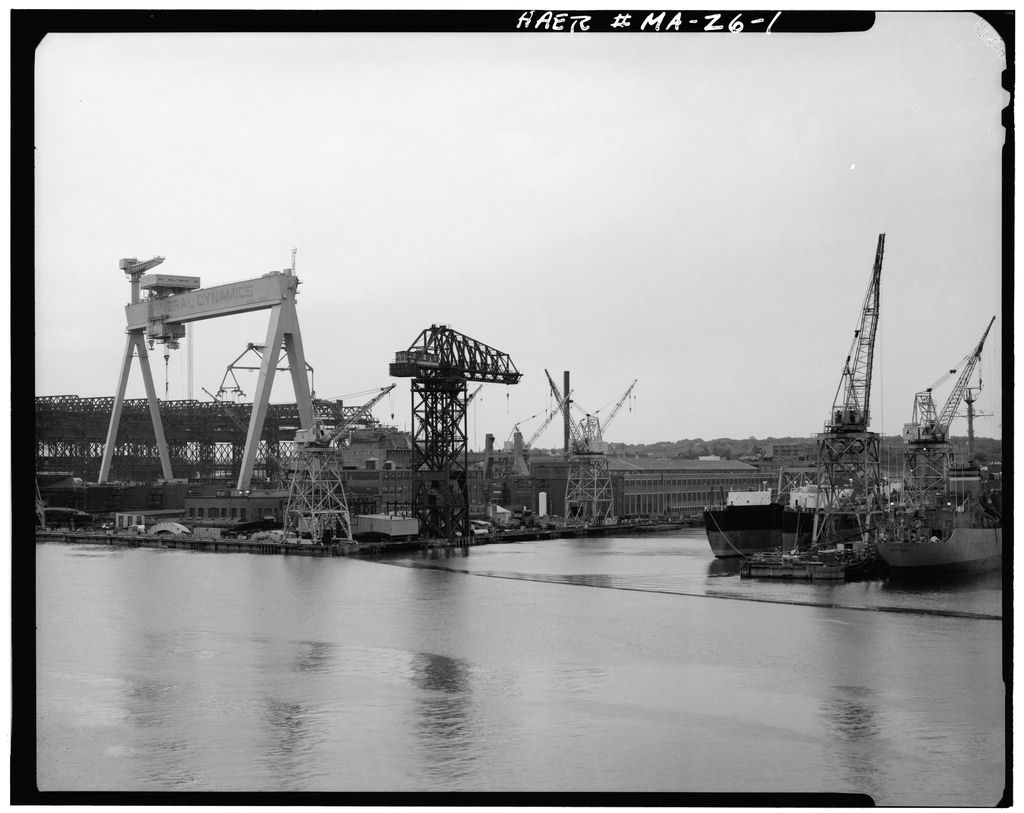
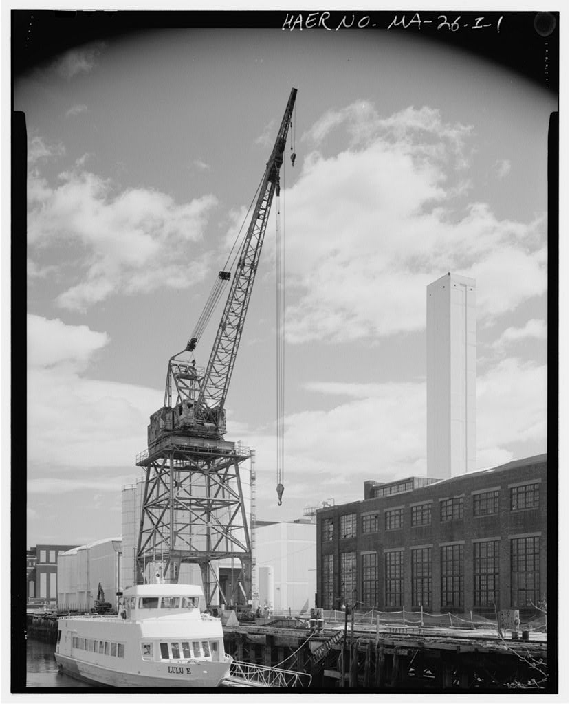
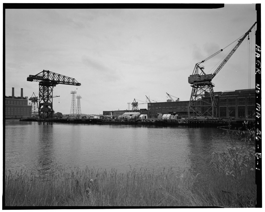
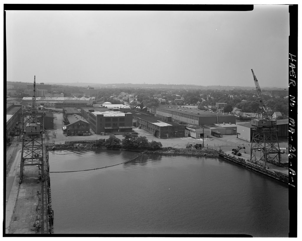
The Massachusetts Water Resources Authority (MWRA) proposes to expand its sludge processing facility at the Quincy-Fore River Shipyard in Quincy, Massachusetts. The proposed project will necessitate the demolition of the Wellman-Seaver Crane. The crane is eligible for inclusion on the National Register of Historic Places as a contributing element to the shipyard. In accordance with measures outlined in a Memorandum of Agreement among the MWRA, the Massachusetts Historical Commission, the Environmental Protection t . Agency, and the Advisory Council on Historic Preservation, Historic American Engineering Record documentation is to be prepared for the crane prior to its demolition.
GENERAL DYNAMICS CORPORATION SHIPYARD, WELLMAN-SEAVER CRANE (General Dynamics Corporation Shipyard, Structure No. HAER No. MA-26-H (Page 2) Preparers: Virginia H. Adams and Matthew A. Kierstead The Public Archaeology Laboratory, inc. 210 Lonsdale Avenue Pawtucket, Rhode Island H. GENERAL DYNAMICS CORPORATION SHIPYARD, WELLMAN-SEAVER CRANE (General Dynamics Corporation Shipyard, Structure No. HAER No. MA-26-H (Page 3) PART
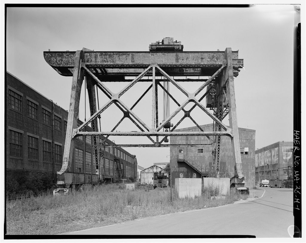
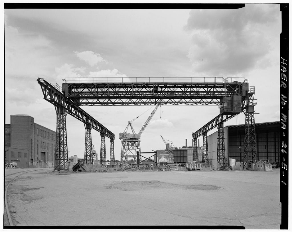
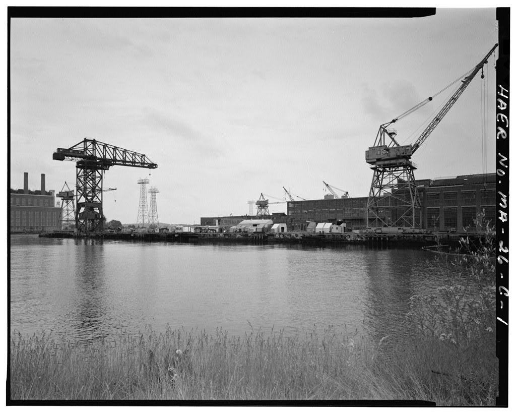
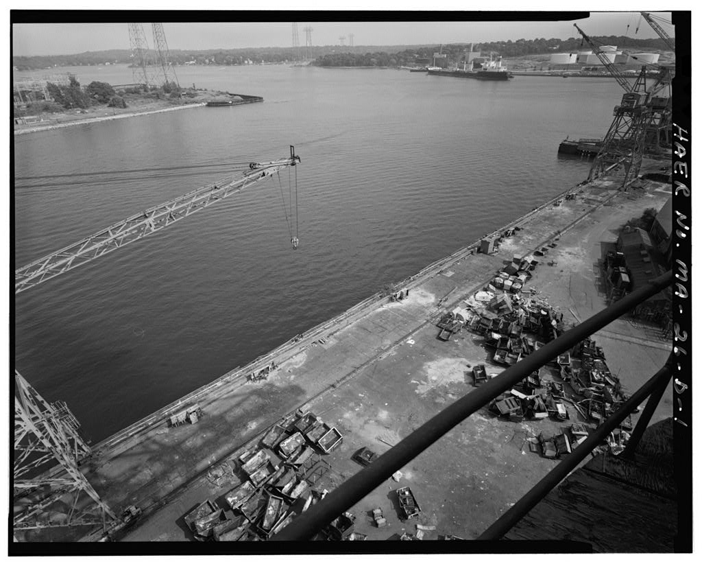
Structure No. or Crane as the Wellman-Seaver Crane is referred to in original documents and drawings of the Quincy-Fore River Shipyard (HAER MA-26), is located at the west end of Outfitting Pier 2 (HAER MA-26-C} in the northeast waterfront area of the yard. Structure 30S is a gantry, or traveling bridge crane, that is a crane constructed with a horizontal overhead hoist beam or bridge raised on electrically propelled side towers, or trestles, which travels in the horizontal plane on parallel guide rails spanning a wide area. As constructed in 1 Structure 30S was also termed a folding gantry crane, as its horizontal bridge extended from the top of the structure to form a hinged boom, which could be raised to clear tall obstructions.
Structure 30S was fabricated from medium steel throughout, and when completed, was painted with a protective mixture of boiled linseed oil and flake graphite. The gantry crane's 56-foot-high superstructure consists of four legs supporting a 75.5-foot long horizontal bridge oriented perpendicular to the direction of travel. The legs are arranged in A-shaped pairs, forming two parallel vertical support towers, or frames, which ride on trucks mounted at the base of each leg. The legs are of riveted box girder construction with lattice bars on the underside. In profile, the legs taper from base to top, and are joined to the bridge and the truck sideframes by curved steel plate gussets and box sections. Both towers are connected across the bottom by a riveted plate girder beam.
On the south side this beam is a tall, level section, with large sheet steel tool and rigging storage boxes slung beneath it. Large concrete and cast iron ingot weights, now scattered around the crane way, were placed on the flat top of the beam as counterweights. Four steel rods with tensioning turnbuckles connect the girder beam to the horizontal bridge above. On the north side, this beam is also of riveted plate construction, however, it is much narrower in section and bows down from the top of the truck mounts, almost to track level at the center. The north legs have been boxed over for most of their length with angle iron and plate to provide reinforcement, with an additional triangular lattice truss and horizontal bracing gusset installed at their apex.
Some additional shrouding has been added to the sideframes, possibly as a safety measure to prevent riggers from climbing underneath them. The two bridge support towers are braced across the craneway by riveted lattice in the form of two X-shaped braces with gusset plates. This allows 21 feet of clearance between the bracing and the rail head. The legs are riveted to the trolley bridge which spans the craneway. The bridge is of riveted steel plate construction and serves as a platform for the two hoist motors and their tracks and trolleys. Trolley movement is now confined to the area between the support towers. To the north, the bridge extends 14 feet 3 inches from the legs, with curved corners on the bottom of the girders, and a small platform across their top surface.
To the south, the bridge ends in a hinged joint. These features are evidence of the crane's previous function as a folding gantry crane. In Pier 2 underwent extensive modifications, which included the installation of a 37.5-ton American Revolving traveling crane. The new crane allowed higher hoisting and greater mobility which made the boom on Structure 30S obsolete and an obstruction. The boom, mast, and supports were removed to accommodate the new crane. As originally constructed, the bridge section continued feet north into a boom, and the north legs of the crane extended upward 48 feet 9 inches from the top of the bridge to form a foot ll sheave wheel mast. The mast was supported by riveted lattice bar trusswork that extended from the top of the mast to the back of the bridge.
There, a housing contained a 25 h. p. hoist motor for raising and lowering the 20-ton hoist and the boom which pivoted from a point at the base of the mast. The boom was supported by a forestay consisting of two pairs of hinged eye bars which spanned from the top of the mast to the end of the boom. Both of the gantry crane hoist trolleys could GENERAL DYNAMICS CORPORATION SHIPYARD, WELLMAN-SEAVER CRANE (General Dynamics Corporation Shipyard, Structure No. HAER No. MA-26-H (Page 4) ride out on the boom when in the lowered position to predetermined distances limited by the weight of the object to be lifted.
The boom could be raised to clear obstructions, and to provide hoisting height for the 20-ton hook that dropped from its tip, however, vertical boom movement itself was not used for hoisting. The operator's cab is mounted near the top of the northwest leg of the crane. A pair of curved iron brackets support the floor of the sheet-steel, shed-roofed cab, which has multi-pane, steel sash viewing windows on all four sides. The cab was originally sided with vertical plank sheathing, and the present cab is a replacement. Access to the cab interior is not possible due to deterioration of the sheet metal door. Access to the top of the crane and the cab is by a ladder, with safety cage, mounted to the northwest leg.
Access to the hoist trolleys is by a catwalk along the west side of the top of the trolley bridge. The crane travels on four trucks, one at the bottom of each leg, with an outer wheelbase of 54 feet on each side. Each truck rolls on two pairs of 36-inch diameter double-flanged wheels running on paired rails laid four feet apart, which span a 53 foot wide staging area, for an overall track gauge of 61 feet. The two eastern trucks are idlers. The crane was driven horizontally by the western trucks, and could move at two speeds, feet or 165 feet per minute. The 100 h. p. main drive motor for horizontal movement is located in a steel housing near the south end of the west side of the trolley bridge.
Horizontal drive shafts extend from the motor housing to the junction of the trolley beam and the legs, where bevel gears transfer the power to vertical shafts extending down to the steel-sheet shrouded geared driving mechanisms. The main power pick-up for the horizontal travel and electric hoists is a trolley shoe extending from the southwest corner which originally contacted a 230-volt catenary wire which ran the length of the crane way on wooden posts. The two hoist motor trolleys move on double flanged wheels along crane rails bolted to the 5 foot 9 inch-high trolley bridge. Both hoists are capable of lifting their hooks 50 feet above the crane rail head. The main 75-ton hoist trolley moves on rails mounted 9.5 feet apart on the top flanges of the trolley bridge girders.
The 25-ton auxiliary hoist trolley moves beneath the 75-ton hoist on strap rails bolted to the inside of the bottom flanges of the trolley bridge girders. The cable winding drum axis for the 75-ton hoist is perpendicular to the beam, and the axis for the 25-ton is parallel. Both hooks are of double-sheave block type and are raised and lowered by a series of cables running from a grooved hoist drum connected by reduction gears to electric hoist motors. Both trolleys pick up current for their electric motors with a rotating flanged shoe that contacts copper power wires mounted along the inside of the beam.
Over its 81 years of use, Structure 30S was subjected to major and minor modifications, including replacement of the main hoist, reinforcement of structural components, and the removal of the folding boom and mast. At present the crane is inoperative, and in fair condition, although the protective yellow oxide paint is starting to fail. The drive and hoist equipment are intact, although they have been exposed to the elements without maintenance or lubrication for 13 years. PART ll
Structure No. The Wellman-Seaver Folding Gantry Crane, erected in is the first and oldest of numerous cranes constructed at the Quincy-Fore River Shipyard. This crane operated under all three shipyard owners, the Fore River Ship and Engine Company, Bethlehem Steel Company, and General Dynamics Corporation, and was referred to by them as Crane The crane is significant as a GENERAL DYNAMICS CORPORATION SHIPYARD, WELLMAN-SEAVER CRANE (General Dynamics Corporation Shipyard, Structure No. HAERNo. MA-26-H (Page 5) surviving turn-of-the-century engineering structure, designed by a noted industrial engineering and design firm.
The crane is significant as a surviving example of the first generation of high-capacity, electrically-driven shipyard cranes which transformed shipbuilding, and shipyard operations, at the turn of the century. The crane was an integral component of the assembly and outfitting process which took place on Pier 2, the oldest outfitting pier in the yard. This crane hoisted and marshalled equipment and materials for the final outfitting and testing of merchant, military, and private vessels from to Originally configured and operated as a more versatile unit, modifications to the crane are a reflection of changes in materials handling at the shipyard and crane technology in general.
Structure 30S was designed by the Wellman-Seaver Engineering Company of Cleveland, Ohio, and fabricated by the American Bridge Company of Ambridge, Pennsylvania. The Wellman-Seaver Engineering Company, organized in was an American engineering firm noted for international design and construction of industrial equipment and facilities. Wellman-Seaver specialized in materials handling and steel mill equipment; their mechanical achievements include the development of the open- hearth charging machine and the Hullet steamship unloader. Structure Wellman-Seaver Contract "No.
is sometimes referred to as a Wellman-Seaver Morgan crane; this is incorrect, as the Morgan name was not added to the company until 1 (Rose Van Tassel and Grabowski During the period major advances were made in shipyard crane technology. The increasing size of ship hulls, and the early introduction of electricity to shipyards, resufted in the development of large, mechanical heavy lifting apparatus. Prior to this material handling revolution, shipyard hoisting was accomplished with increasingly inefficient man or animal-powered rigs. The combination of electricity and steel fabrication resulted in the appearance of efficient, high-capacity gantry cranes at new shipyards, including the Fore River Ship and Engine Company yard at Quincy.
The Wellman-Seaver Folding Gantry Crane, although modified, is an example of the early electrified shipyard crane technology which made possible advances in the speed and size of ship assembly in the first years of this century (Fassett, Structure 30S was built at a period in industrial design when lingering Victorian decorative touches in machinery were losing favor to more streamlined, functional designs. Although the crane is a highly functional, skeletal machine with its working mechanisms exposed, several unusual, curvelinear features such as the flaring control booth support brackets and brace gussets and the swells of the "feet" and "shoulders" of the side towers give the crane a more graceful appearance than later examples of this type of engineering.
The Wellman-Seaver crane was erected in 1 901 by the Fore River Ship and Engine Company to serve their new main shipbuilding pier, later referred to as Outfitting Pier 2, located along the south side of a wet basin formed by the outlet of Bent's Creek. The term outfitting refers to the finishing work performed to a boat after the hull has been constructed and floated. Structure 30S was integrated with the materials handling system at the shipyard, with both vehicular and railway access to the crane way.
The tracks of the shipyard's railway, the Fore River Railroad Company, ran under the crane for the length of the craneway, connecting the crane to most buildings in the shipyard, and ultimately to a junction with the New York, New Haven and Hartford Railroad in South Braintree, Massachusetts. This arrangement permitted a smooth flow of equipment originating both inside and outside the yard to the pier and crane. As Outfitting Pier 2 was enlarged, the Wellman-Seaver's range was extended. The crane rails were supported by steel plates laid on concrete footings resting on timber pilings and cribbing, originally GENERAL DYNAMICS CORPORATION SHIPYARD, WELLMAN-SEAVER CRANE (General Dynamics Corporation Shipyard, Structure No. HAER No.
MA-26-H (Page 6) extending 280 feet along the east end of pier. In pier modifications increased crane travel by 180 feet, allowing the crane to have full access to the length of the pier. In the pier structure was substantially rebuilt, and crane travel was extended 276 feet, allowing Structure 30S to travel to its present western extremity near the middle of Building 11 {Machine Shop) immediately to the south. As originally erected. Structure 30S was rated as a 75-ton crane, however, this did not indicate the capacity of just a single hoist and hook. The crane was erected with a 50-ton main hoist and an auxiliary 25-ton hoist. With the use of an equalizer bar hung from both hooks, the crane could lift up to 75 tons, depending on how far out on the boom the trolleys were located.
In the first years of this century, the Fore River Ship and Engine Company was receiving commissions to build ever-larger naval craft, which taxed the financial resources of the company (Boston Affiliates, Inc. The increasing size of the new ships being constructed also put pressure on physical resources at the yard. It was not an uncommon practice for shipyards to modify or even purchase yard equipment in order to complete specific commissions (Hasselbach, 1 Evidence of this practice at the Fore River Ship and Engine Company shipyard can be seen through examination of the Structure 30S drawings. "Drawing No. dated September 29, was drawn to show specific weights and clearances for crane use when lifting the heavy, armored gun turrets for the Argentinean battleship Rivadavia.
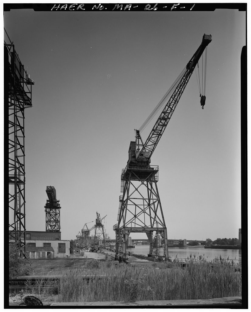
The drawing indicates that the 50-ton main hoist was replaced with a 75-ton unit, and that the trolley wheel stops on the main hoist rails were extended five feet. Another notation indicates that in order to hoist the turrets for the Rivadavia or the North Dakota, the 25-ton trolley had to be parked at the far opposite end of the boom from the turret to serve as a counterbalance. After the crane actually had a capacity of 100 tons (General Dynamics Corporation). At some point after the 1 929 erection of the McMyler Hammerhead Revolving Crane (HAER MA-26-G), at the east end of Pier No.2, the folding boom on the Wellman-Seaver Crane was removed, as it had become obsolete, and an obstruction.
The boom was replaced with a smaller hoisting derrick mounted at the northeast corner of a second operator's cab platform, located on the vertical folding boom sheave mast. After the erection in 1 940 of the taller and more versatile American Revolving Crane on Pier 2, the small hoisting derrick was removed, along with its hoisting motors, and the sheave mast superstructure. As both cranes now actually shared one of Pier 2's crane rails, the range of lateral movement of Structure 30S was limited by the location of the American Revolver. These major structural changes may have prompted the addition of the welded steel plate and angle reinforcements at the north legs, which previously continued upward to form the sheave mast superstructure.
Structure 30S was originally the primary outfitting crane at the Quincy-Fore River Shipyard. After the erection of the American Revolving Crane, however, Structure 30S reverted entirely to its other role of unloading trucks and railroad cars, marshalling outfitting equipment and supplies in the extended storage yard along the pier between the crane rails, and spotting objects for the larger American Revolving Crane and the Hammerhead Crane, erected in 1 The only other modifications made to Structure 30S include sheet steel safety shrouds welded to potentially dangerous areas such as the drive truck wheels and sideframes.
Structure 30S was used infrequently during the General Dynamics years, According to informal conversations with several former shipyard employees encountered during fieldwork, the crane was used primarily for the occasional handling of propellers before it was decommissioned in In the bearing piles under Pier 2 were found to be deteriorated and gantry crane movement on the pier was restricted (Fitch General Dynamics File Memo). The "Certification of Handling Gear" inspection records for the crane indicate that it was last used in when it was parked at the western-most end of its horizontal travel rails (Giacchetti General Dynamics Corporation). GENERAL DYNAMICS CORPORATION SHIPYARD, WELLMAN-SEAVER CRANE (General Dynamics Corporation Shipyard, Structure No. HAER No.
MA-26-H (Page 7) PART 111 SOURCES OF INFORMATION A. Plans and Drawings General Dynamics Corporation. File Records located at Quincy-Fore River Shipyard, Quincy, Massachusetts. B. Historic Views Quincy Historical Society. Erection Photograph, c. Photo No. C. Bibliography Boston Affiliates, Inc. Quincy-Fore River Shipyard Historic Resources Survey and Addendum. Prepared for Massachusetts Water Resources Authority, Boston, MA, October 20, and January 2, Fassett, ed. The Shipbuilding Business in the United States of America. New York: Society of Naval Architects and Marine Engineers, # Fitch, Virginia A. Historic American Engineering Record Addendum to General Dynamics Corporation Shipyard, Quincv, Massachusetts HAER No. MA-26.
Pawtucket, Rl: The Public Archaeology Laboratory, Inc., General Dynamics Corporation. File Records located at Quincy-Fore River Shipyard, Quincy, Massachusetts, Rose, William Ganson. Cleveland: The Making of a City. Cleveland: The World Publishing Company, Van Tassel, David D. and John J, Grabowski, eds. The Encyclopedia of Cleveland History. Indianapolis: Indiana University Press, D. Interviews Giacchetti, Steven J., Manager Facility Engineering, Massachusetts Water Resources Authority, Fore River Staging Area. Interview by Matthew Kierstead, 26 June Quincy, Massachusetts. Hasselbach, Kurt, Curator, Massachusetts Institute of Technology Museum, Hart Nautical Collection. Interview by Matthew Kierstead, 21 July, Cambridge, Massachusetts. .
 Block
Block