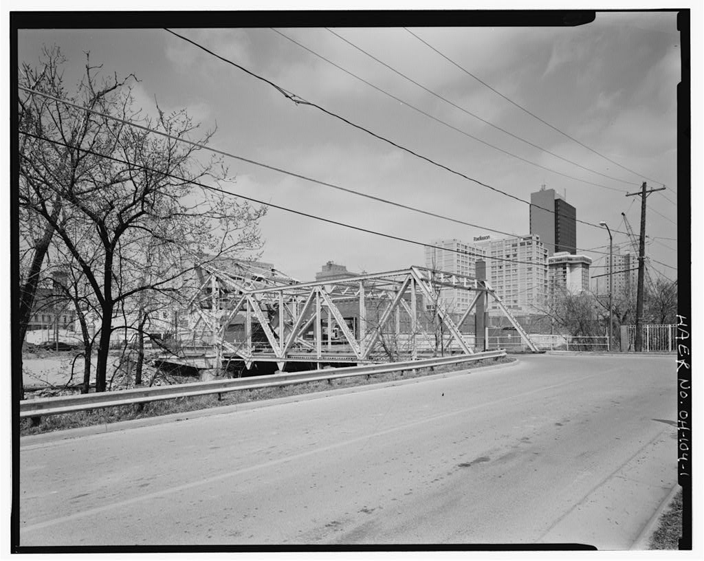
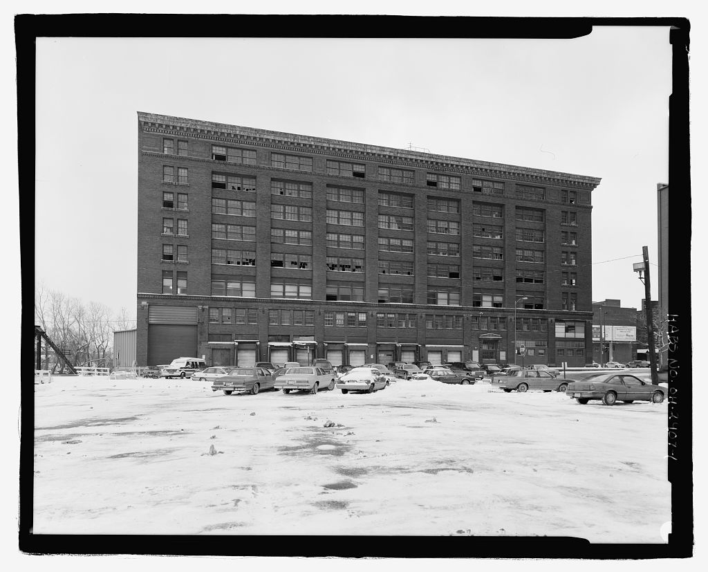
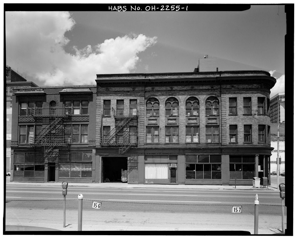
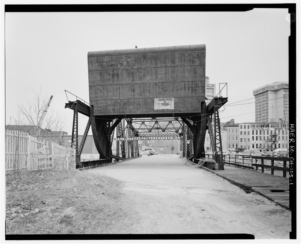
The Washington Street Bridge deck upgrade is part of the Owens-Corning Fiberglass World Headquarters Project that is currently taking place on the Middlegrounds. Due to the projected increase in vehicular traffic, it was necessary to increase the load strength, while trying to preserve the historic character of the bridge. The project proposes the removal of the bridge from its current foundation, the installation of a fake counterweight and a new concrete pile foundation and deck, and re-installation of the original bridge truss-work. The original deck, counterweight and rolling girders will not be re-used. Christopher B. Owen Cultural Resource Specialist Midwest Environmental Consultants, Inc. Southwyck Boulevard Toledo, Ohio WASHINGTON STREET BRIDGE HAERNo. OH-104 (Page 2) PART I.
HISTORICAL INFORMATION A. Physical History 1. Date of erection: The original metal bridge plate is stamped The original bridge plans bear a design date of August, 2. Engineer: William Scherzer. The Scherzer Rolling Lift Bridge Company, Monadnock Block, Chicago, Illinois, was founded by William Scherzer. In using the patented scherzer movement, William Scherzer was retained by the Metropolitan West Side Elevated Railroad Company of Chicago to design a four track draw bridge to span the Chicago River, it was not until that the Scherzer Rolling Lift Bridge Company was formed. Scherzer's patented rolling lift bascule bridge design was used throughout the United States, as well as many foreign countries including St. Petersburg, Russia.
By Scherzer had built four bridges in Great Britain with others in Holland, Argentina, India, and Egypt. 3. Builder, contractor: The Toledo Bridge and Crane Company of Toledo, Ohio. The Smith Bridge Company, a predecessor to the Toledo Bridge and Crane Company, was incorporated in by R. W. Smith for the manufacture of wooden bridges, under patents which he held. The business was carried on successfully for several years with the bridge timbers being framed in Toledo and shipped to their destination. When steel replaced wood as the primary bridge-building material, about the Smith Bridge Company changed its name to the Toledo Bridge Company and began to manufacture steel bridges.
In after a new factory was erected and equipped with modern bridge-building machinery, the Toledo Bridge Company became the Toledo plant of the American Bridge Company. In the Toledo Bridge Company and the Massilon Bridge Company merged into the Toledo Bridge and Crane Company. The American Bridge Company remains in the City of Toledo and last appears in the Toledo City Directories in The Toledo Bridge and Crane Company manufactured bridges and bridge materials that have been shipped to all parts of the country. The company also manufactured electric traveling cranes and coal and ore handling machinery. The final subsequent development of the company is unknown, but last appears in the Toledo City Directories in WASHINGTON STREET BRIDGE HAER No. OH-104 (Page 3) 4.
Original plans and construction: The original cost of the bridge is unknown. The original plans and early photographs show the Washington Street Bridge as a scherzer movement, Warren through- truss steel bascule drawbridge with riveted connections and a wood deck with steel stringers and floor beams. The horizontal top chord is inclined between the fifth panel and the counterweight. The bridge has rolling track span and three reinforced concrete piers. 5. Alterations and additions: Although the Washington Street Bridge has undergone numerous alterations, it is difficult to date these alterations because of a lack of documentation by the City of Toledo, Street Bridges and Harbors Department.
However, it is felt by the author that these alterations occurred after the bridge was taken out of operation in circa The most notable alterations are the removal of the operating mechanisms including the electric motor, the operator's house, the bridge locking system, and the gear drive system, including the rack support. The original wood decking has been replaced by a wood deck covered with asphalt paving, making it very difficult for the bridge to be put back in operation. Metai braces have been welded to the curved quadrant from the rolling lift track girder, preventing any accidental opening of the bridge. A weight restriction has been placed on the bridge. B. Historical context: The City of Toledo grew rapidly after the Civil War.
From to Toledo became an important commercial and manufacturing city, as well as the third largest rail center in the nation and a major shipping point for coal and iron. As Toiedo expanded, so did the need for greater rail space, and the Middlegrounds peninsula was filled in to satisfy this need for additional railyards. In addition to railyards, train stations, warehouses, and hotels (including the Oliver House, the last surviving hotel) were located on the Middlegrounds. The proximity of the facilities permitted the easy transfer of bulk and finished goods between the large Great Lakes ships, the canal boats, and the trains. Access to the Middlegrounds was restricted by the same commercial shipping enterprises that it was servicing so well.
With the Maunriee River on the east, and the Miami and Erie Canai on the west, the only convenient and economical access to the Middlegrounds from the Central Business District was by a bridge(s) over the canal. The WASHINGTON STREET BRIDGE HAERNo. OH-104(Page4) height of canal and shipping vessels required the use of a drawbridge to cross the canal, in the City of Toledo contracted with the Toledo Bridge and Crane Company to construct the Washington Street Bridge to gain access to the railyards on the Middlegrounds. After the canal was closed in a portion of the canal, from the Maumee River headwaters, was used for local shipping and small boat traffic. Eventually this portion was no longer needed and it was closed to shipping in Shortly thereafter the bridge was taken out of service.
Redevelopment plans for the Middlegrounds Owens-Corning Fiberglass World Headquarters determined that the Washington Street Bridge was not structurally capable of supporting the projected increase in vehicular traffic. It was therefore necessary to increase the load strength, while trying to preserve the historic character of the bridge. Scheduled for late the project proposes the removal of the bridge from its current foundation, the installation of a fake counterweight and a new concrete pile foundation and deck, and the re-installation of the original bridge's truss-work. The original deck, counterweight and rolling girders will not be re-used. PART II. DESIGN INFORMATION A. General Statement: 1.
Design character: Built in the area adjacent to the Bostwick-Braun Building and the Middlegrounds, this steel Warren through-truss bascule drawbridge has a Scherzer rolling lift movement, riveted connections and a wood deck with steel stringers and floor beams. These construction elements combine to make this bridge locally and nationally significant. The Washington Street Bridge is a Scherzer Rolling Lift bascule bridge consisting of seven panels, inclined end posts, curved or quadrant girders, a concrete counterweight, reinforced concrete piers, and a rolling lift track span. The rolling lift span sits on two reinforced concrete piers. The operator's house was attached to the rolling lift track girder on the south elevation.
The house was approximately by 11'-O" in size and was structurally attached to the bridge. Details of the operator's house placement can be seen in the general plan. WASHINGTON STREET BRIDGE HAERNo. OH-104(Page5) Designed with a utilitarian purpose, there are no decorative elements found on the bridge. 2. Condition of fabric: The overall fabric of the bridge is in sound condition. Some of the riveted joints show surface rust. The reinforced concrete piers show some spalling, but are structurally sound. B. Description: 1. Over-all Dimensions: The Washington Street Bridge has two spans with an overail length of The bascule through truss is in length and the rolling lift track span is in length. The bridge is approximately above the water level.
The height from the road surface to the top of the top-chord is 1 at the inclined end post end. The height from the road surface to top of counterweight is approximately The bridge carries a two lane roadway that is wide from curb to curb. The bridge is wide from center to center of the lower chord truss. The cantilevered walkway is wide. Exact detail measurements of all segments and components of the bridge can be found on the original drawings. 2. Foundations: The Washington Street Bridge rests on reinforced concrete foundations. A pier is located at the end of the moving span and each end of the rolling lift track span. The reinforced concrete piers on which the rolling lift track span was placed were subject to the greatest amount force and required extensive engineering.
This span was subjected to both the dead weight of the bridge and the live and rolling weight of the moving span. Thus, these reinforced concrete piers had to be placed on rock and/or very solid soil and engineered to withstand the shifting forces. The depth of the piers into the creek bed was not specified in the bridge plans. The clearance between the waterway piers was 3. Structural system: The Washington Street Bridge employs the most common type of Warren truss, using rigid posts for both vertical and diagonal members. However, the vertical members are not as substantial as the diagonal members. The top and bottom chords, end post, vertical post, diagonal posts, struts, and portal struts are assembled using lattice bracing.
The top lateral bracing, sway WASHINGTON STREET BRIDGE HAER No. OH-104 (Page 6) bracing, floor beams, and stringers are all made with solid steel. The curved quadrant and rolling track supported the bridge when the bridge was being operated and allowed for the bridge to be smoothly rolled back to permit the passage of canal shipping traffic. The curved quadrant was constructed using a curved track with projecting trapezoidal teeth recepticais that engaged the teeth on the roiling track. The roadway was constructed of two layers of diagonally laid wood planks. These planks were supported by steel floor beams and stringers. The wood planks were light enough to reduce the weight of the bridge but also provided enough structural strength to support vehicular traffic.
The numerous bridge components are joined by riveted connections. By the Toledo Bridge and Crane Company was probably using the mass production technique developed by the King Bridge Company of Cleveland, Ohio. Many of these components were probably preassembled in sections and painted at the Toledo plant, and then delivered to the site by rail for final assembly. 4. Mechanical system: The Washington Street Bridge was designed to operate by electric motor, run from the operator's house. To operate the bridge, a lever (running the length of the lower chord on the south elevation) was thrown releasing the locking mechanism at the end of the bridge opposite the counterweight and rolling lift mechanism.
The electric motor was attached to a gear that engaged an elevated horizontal track, pulling the bridge back in a horizontal motion. As the bridge moved, the curved quadrant with projecting teeth recepticais would engage the lower track teeth, thereby "rolling" the bridge back and "lifting" the bridge out of the way. When the bridge was in the full open position, the counterweight would sit on the deck of the approach prohibiting the traffic from proceeding. The opposite approach had a barricade of some type to prevent traffic from proceeding. 5. Technology: Bascule bridges were commonly found in those areas where space was at a premium.
Urban areas that were congested with buildings, railroads and railyards, and vehicular traffic, and disrupted by rivers, lakes and waterways, presented further constraints on the type of bridge that could be built. High-level WASHINGTON STREET BRIDGE HAERNo. OH-104(Page7) bridges with long approaches were not practical because they required a tremendous amount of land. The solution was a ground level bridge that could move its deck out of the way of river traffic while taking up a minimal amount of land. Only A few types of bridges meet these design parameters. Although the swing bridge required short approaches, it required a center pier that took up vita! space in the shipping lane, and was subject to bumping and ramming, which could take the bridge out of commission.
This bridge type also required a lengthy time period to open and to close, causing delays in waterway and vehicular traffic. While some swing bridges had mechanical motors, other bridges employed bridge operators to turn the gears. Drawbridges required a powerful steam or electric motor. These large motors took up critical space, and some drawbridges required more than one motor to operate. In addition, drawbridges did not provide a full vertical clearance. If tall ships had to use the shipping lane, a longer bridge had to be built to increase vertical clearance. A longer bridge approach also consumed precious urban space. The Scherzer Rolling Lift Bridge countered these problems.
The bridge was designed to easily lift a bridge back out of the way of boat traffic, use a minimal amount of land, and provide a full vertical clearance, while requiring a smaller, less powerful motor to operate. The bridge was designed to use a wood bridge deck and counterweight. A wood deck provide the needed support at a reduced weight, unlike a metal or paved deck. In addition, the counterweight was used to offset the dead, rolling and live weight that the bridge would experience. A compact electric motor was more than sufficient to raise and lower the bridge and could be located within the confines of the bridge's framework.
The Scherzer Rolling Bridge was designed to roll back on a curved quadrant, pulling the bridge completely out of the shipping channel and leaving an open vertical clearance. With the bridge out of the way, concerns about boat height and potential to impact the moving span were greatly reduced if not eliminated. The patented Scherzer movement employed a curved quadrant and a smooth track recessed with trapezoidal teeth recepticals that engaged the teeth on the rolling track. This movement allowed the bridge to roll back without slippage of the bridge's tracks. WASHINGTON STREET BRIDGE HAER No. OH-104 (Page 8) The counterweight, in addition to offsetting the weight of the bridge, provided a safety measure.
When the bridge was in the full open position, the counterweight would sit completely on the deck of the approach. This acted as a barrier preventing any vehicle from accidentally driving into the waterway. PART III. SOURCES OF INFORMATION A. Original Architectural Drawings: The original canvas drawings are archived with the City of Toledo, Street Bridges and Harbors Department, W. Central Avenue, Toledo, Lucas County, Ohio. These drawings are very brittle and arrangements must be made in advance in order to view them. B. Early Views: The Toledo Lucas County Public Library, Local History Room, 325 N. Michigan Avenue, Toledo, Lucas County, Ohio has early views of the Washington Street Bridge and the surrounding area.
These early views are located in the Industries, Bostwick-Braun file, the Bridges file, the Canal file, and the Railroads file. C.
 Block
Block