Documentation of the New Bedford-Fairhaven Middle Bridge is part of the Massachusetts Historic Bridge Recording Project, conducted during the summer of under the co-sponsorship of HABS/HAER and the Massachusetts Department of Public Works, in cooperation with the Massachusetts Historical Commission. Patrick Harshbarger, HAER Historian, August NEW BEDFORD-FAIRHAVEN MIDDLE BRIDGE HAER No. MA-101 (page 2) Description The Route 6 harbor crossing between New Bedford and Fairhaven consists of two highway sections on harbor islands and three bridge sections between the islands and the mainland. The West Bridge between downtown New Bedford and Fish Island has ten plate girder spans ranging from 33' to 71' in length.
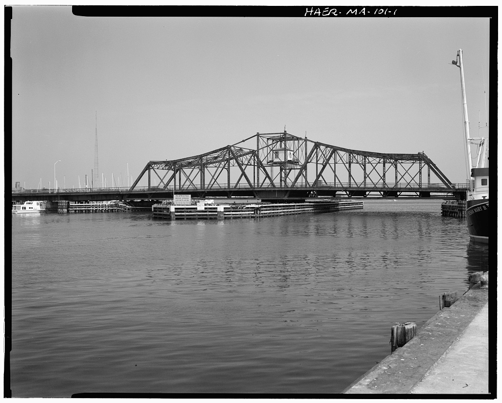
The Middle Bridge spanning the main channel between Fish and Popes Island consists of a 288-foot swing span and five plate girder spans ranging from 73' to 82' in length. The East Bridge, which spans the channel between Popes Island and Fairhaven, has nine plate girder spans, each approximately 73' in length. The total length of the entire crossing, including the three bridge sections and portions of highway on Fish and Popes Island, is approximately The entire crossing is known collectively as the New Bedford-Fairhaven Bridge.(See Figures 1 and 2.) The focus of this report is the Middle Bridge, and in particular the rim-bearing swing span.
The Massachusetts Department of Public Works replaced the superstructure of the plate girder spans in The swing span is the only portion of the Middle Bridge that has not been significantly altered.1 The Middle Bridge consists of a swing span and five plate girder spans, one to the west and four to the east of the swing span. All of the spans are supported on stone piers. The Middle Bridge is approximately in overall length. According to the Massachusetts Department of Public Works database, the 289-foot swing span is the longest moveable span among the forty-four moveable bridges which fall under the Department's purview.2 The swing span measures in width between the trusses and to the edges of the sidewalks.
At its highest point, the bridge is 61' from the lower chord to the coping of the central tower. The lower chord is approximately 8' above mean high water. The roadway sits about 1' above the bottom of the lower chord. The lower chord is made of two 18-inch steel plates, spaced 20" apart, with two angle irons to each plate, tied together with lattice bars. The upper chord is made of two 21-inch plates, also 20" apart and joined by angle irons and lattice bars. Verticals join the upper and lower chords at intervals of Steel pins ranging from 34" to 8k" in diameter connect the verticals and chords. The verticals are made of two 12-inch steel channels, 12" apart, joined by lattice bars. The diagonals and counters are composed of flat eyebars from 3k" to lhn in width.
The upper lateral bracing and struts consist of channels, some joined by lattice bars. The upper lateral struts have ornamental brackets where they join the verticals. The structural action of the swing span changes depending upon whether the bridge is open or closed. When the swing span is open it rests solely upon the center pier and acts like a double cantilever. When the span is closed it rests upon the piers and acts like two through trusses, one on either side of an independently-standing central tower. The panels on either side of the tower differ structurally from their neighbors. The diagonals are made of two 21-inch steel plates, %" thick, with four angle irons joined by lattice bars.
These heavily constructed diagonals act as endposts to the NEW BEDFORD-FAIRHAVEN MIDDLE BRIDGE HAER No. MA-101 (page 3) double trusses when the bridge is in the closed position. The upper chord between the diagonals and the central tower is constructed of two pairs of eyebars joined in the middle by a 7-inch pin. In the closed position these eyebars are free from strain, but in the open position they carry the weight of either arm of the span. When the bridge reaches the closed position, hydraulic jacks lift the ends of the span approximately 3", then steel wedges are inserted between the bridge and the stone piers by hydraulic pressure. This lifting action causes the eyebar links in the upper chord to go slightly slack.
When the bridge operators prepare to open the span, the wedges are released and the bridge lowered, returning strain to the eyebar links. The hydraulic jacks are 12" in diameter with a 6-inch stroke, and are held in position when at rest by four cast steel blocks which are pushed in and drawn out by hydraulic rams 4" in diameter and 36-inch stroke. The tower verticals are made up of double channel irons with lattice bars. They are 61' high and topped by copper finials of ornamental design. The center tower is approximately 20' long and 54' wide. The operator's house, 20' above the roadway in the central tower, is a wood-frame structure with shed roof. The operators house contains the controls for operating the hydraulic jacks and for engaging the swing mechanism.
When open, the whole draw span rests on two box girders, stiffened at 2-foot intervals by cross angle irons, and joined at the top by a steel plate, 4" thick. These two girders, in turn, rest upon a system of four girders that, in turn, rest upon the circular steel drum upon which the bridge turns. The four girders provide stability and distribute the weight of the swing span evenly upon the drum. The drum is 50" deep and approximately 36' in diameter. It is made of H" - thick riveted steel plates. The drum turns on sixty-nine steel rollers, 18" in diameter. The axles of the rollers are attached to a spider frame running to the central pin of the turntable.
According to the construction plans, the concrete and stone center pier rests on piles driven to a depth of 46' below the harbor floor. Two electric motors supply the power to turn the bridge. The motors are housed inside the drum. When engaged each motor turns a separate system of beveled gears that transfer the power to two vertical shafts on the drum's exterior. In turn, these shafts operate a pinion gear moving along a rack on the circumference of the drum. The gears and shafts operate in opposition to each other, 180 degrees apart on the drum's circumference. An additional electric motor inside the drum supplies power to the hydraulic pump that operates the jacks and wedges. The floor of the bridge rests on steel floor beams riveted to the lower chord and verticals.
Between the floor beams run I-beam stringers that support a steel grid deck filled with concrete. Brackets support wood plank sidewalks outside the trusses A wood-frame bridge tender's house with lounge and lockers for the operators is cantilevered on the southern side of the western approach span to the swing bridge. During the summer, the operators open the bridge on a fixed schedule of fifteen minutes after every hour, and more frequently in the early morning when the fishing boats leave port. During the winter, the bridge operates on a reduced schedule of openings. The operators work three eight hour rotating shifts, and two bridge operators are on duty at all times. One NEW BEDFORD-FAIRHAVEN HIDDLE BRIDGE HAER No.
MA-101 (page 4) operator works the controls in the operating house above the deck and the other unlatches the ends of the bridge via a manual control, monitors the closing of the bridge gates, and signals the operating house when all boats have cleared the bridge.3 The swing span has a 95-foot navigational clearance to the west and a 94-foot clearance to the east. The eastern channel is currently closed because of fender damage caused by an errant freighter. The fenders consist of creosoted piles sheathed by wood planking.
The bridge's dedication plaque has been removed, but a drawing of it is located in the Massachusetts Department of Public Works bridge files.(See Figure 3.) Early Bridges at New Bedford-Fairhaven In the New Bedford newspaper proudly proclaimed, "The draw span of the New Bedford and Fairhaven bridge will be one of the longest and finest in New England, and one of the greatest draw bridges of the country. Nothing this side of New York will equal it, and in some respects it will be the only one of its kind."4 Indeed, the Middle Bridge is noteworthy for its size and its innovative truss design. It is also important for its association with two nationally significant engineers. George F.
Swain, consulting engineer for the project, pioneered in the field of structural design and developed the engineering curriculum at Massachusetts Institute of Technology (M.I.T.) and Harvard University. William Fish Williams, the supervising engineer, became well known for his ability to manage large public works projects. Following the New Bedford-Fairhaven Bridge, Williams oversaw construction of the Cape Cod Canal, and (as Massachusetts Commissioner of Public Works) over in highway improvements.5 The citizens of New Bedford and Fairhaven consider the draw span a landmark in the history of their cities. Over the past four decades, plans to replace the swing span have met with strident calls to save the bridge.
Proponents of a new bridge argue that the old draw regularly delays traffic and limits the size of ships that can enter the northern portions of New Bedford harbor. Preservationists embrace the old bridge for its historic value and beauty. They also claim that the draw can be rehabilitated more cheaply than a new bridge can be built. Local newspaper editorials show that feelings run deep on both sides of the issue. Controversy is nothing new to the New Bedford-Fairhaven Bridge. Since the the bridge has been seen as vital to the economic prosperity of New Bedford. It has been periodically damaged by storms, battered by boats, and worn out by traffic, yet it has always been repaired and rebuilt.
The First New Bedford-Fairhaven Bridge In the Massachusetts General Assembly granted to William Rotch of New Bedford the right to build a toll bridge across the Acushnet River at New Bedford Harbor. The growth of New Bedford's population, the expansion of the whaling industry, and the long overland trip around the harbor prompted the town's leading citizens to petition the General Assembly. William Rotch and the other proprietors of the New Bedford-Fairhaven Bridge owned whaling ships NEW BEDFORD -FAIRHAVEN MIDDLE BRIDGE HAER No. MA-101 (page 5) and represented New Bedford's business interests. They probably hoped to build new wharfs and warehouses on Fairhaven's less-crowded shoreline while turning a profit from bridge tolls.
In the proprietors opened a 24'-wide bridge with two 30' draws, one between New Bedford and Fish Island, and the other between Popes Island and Fairhaven. The bridge appears to have been a wooden trestle supported by pilings and stone piers. It cost 60 for a pedestrian to cross, 6C for a horse, 35C for a four-wheeled wagon, and 6C for a dozen sheep, pigs or cattle. The General Assembly mandated toll rates to keep the proprietors from charging high fees for use of their bridge. The New Bedford and Fairhaven Bridge's location made it particularly susceptible to damage from ocean storms. In a wind-driven tide inundated the bridge and partially destroyed it.
Finally in September a hurricane lifted the entire bridge from its piers and dashed it into splinters.7 New Bedford-Fairhaven Bridge The proprietors did not complete the rebuilding of a new bridge until The facts concerning this bridge are sketchy at best. In the General Assembly passed an act authorizing the proprietors to widen the two draws to although apparently they had already been widened from the original 30-foot specification. The increased navigational clearance made wharf property to the north of the bridge accessible to larger ships, and therefore more valuable. Except for the widening of the draws, the structure appears to have survived with only routine repairs until when another September storm destroyed the bridge.
Only five days after the storm, a special committee of the General Assembly met in New Bedford to discuss the bridge's fate. A survey reported that the bridge consisted of of earthenwork, of trestle work, and ranged from 26' to 33' in width. The Fairhaven-Popes Island draw had not been operated in a number of years. At this meeting it was decided that the bridge would be taken from the proprietors, who apparently did not wish to repair the bridge, and awarded to the care of the Bristol County Commissioners. The proprietors received for the bridge, one-third of the cost paid by Bristol County, one- fifth by Fairhaven, and seven-fifteenths by New Bedford.
The public bridge would not charge a toll.8 New Bedford-Fairhaven Bridge The County Commissioners made repairs to the bridge but did not substantially alter its construction. The first photographic evidence of the bridge dates from this period and shows a narrow, wooden bridge with alternating stringers and low trusses between piers of timber cribbing and stone. The swing spans had a central tower made of iron truss work with guide wires running from the top of the tower to either end of the draw. By the New Bedford and Fairhaven Street Railway Company had installed a line of tracks across the bridge, and horse-drawn cars began carrying passengers across the river. In the railway introduced electric street cars. NEW BEDFORD-FAIRHAVEN MIDDLE BRIDGE HAER No.
MA-101 (page 6) A New Bridge For New Bedford Harbor By the heavier traffic had begun to take its toll on the narrow wooden bridge. In newly-elected New Bedford Mayor Jethro C. Block called on the county commissioners to replace the antiquated structure. Brock's speech gave birth to the bridge that stands today, but not without Herculean efforts. Although the county commissioners operated and maintained the bridge, the Massachusetts General Assembly authorized major improvements. The cost of the new bridge would be born primarily by the city of New Bedford, and to a lesser degree by Bristol County, Fairhaven, and other surrounding towns.
In Massachusetts, the town and city governments have traditionally been stronger than that of the county; with the county's commissioners making most of the decisions and the municipalities paying the largest part of the bill, a few feathers were bound to be ruffled. The General Assembly expeditiously passed an act authorizing for improvements, but the county commissioners continued to drag their heals. New Bedford's leading newspapers charged a commissioner from Fall River of attempting to award the bridge contract to some political cronies, and Fall River's newspapers accused New Bedford's commissioner of forcing the county to pay for a bridge that was solely to the benefit of New Bedford. Other controversies soon arose.
First, Fairhaven's residents argued over what street the new bridge would enter town. It was finally agreed to place the eastern terminus a block north of the old Bridge Street site. Second, the bridge at the New Bedford abutment crossed over the New York, New Haven, and Hartford Railroad at grade. New Bedford's city council had recently passed an ordinance abolishing at grade crossings and had entered into discussions with the railway about what portion of the costs of regrading the company should bear. The railway refused to pay for a portion of the bridge, even though it made sense to the city council that the new bridge should be extended to cross over the railroad's right of way.
Third, the War Department insisted that the draw span be placed between Fish Island and Popes Island, instead of between Fish Island and New Bedford, where it had been since The War Department held authority over bridge clearances over navigable inland waterways and demanded a wider main channel than could be afforded in the old one. Owners of wharves north of the bridge objected, saying the change would hurt property values and cause problems with the natural currents of the harbor. Fourth, a manufacturer on Popes Island argued that changing the grade of the bridge would place the ground floor of his factory below the roadway. Additionally, construction would significantly disrupt the shipment of goods to and from his business.
The manufacturer proceeded to seek an injunction against construction of the bridge. The year came and went, and still no progress had been made. Finally, the situation became so intolerable that the General Assembly took the project out of the hands of the county commissioners. An agreement was reached by which the New Bedford city engineer would oversee the construction of the bridge, while the county maintained ownership.11 William Fish Williams City Engineer William Fish Williams was a man with New Bedford roots. NEW BEDFORD-FAIRHAVEN MIDDLE BRIDGE HAER No. MA-101 (page 7) The son of a New Bedford whaling ship captain, Williams had been born at sea somewhere between New Zealand and Tasmania.
The first seven years of Williams life were spent aboard various vessels of which has father was master. He received his early education in the public schools of Oakland and San Francisco, and as a young man decided to pursue an engineering career. He graduated from Columbia University with a degree in civil engineering in and with a degree in mining engineering in For a number of years Williams worked at mines in Utah and Colorado, and then after marrying and starting a family opened a private practice in Hartford, Connecticut. In in anticipation of a job on the Nicaraguan Canal route, Williams moved his family to his aunt's home in New Bedford.
After a brief trip to Nicaragua, followed by the failure of the canal, Williams returned to New Bedford where the mayor appointed him city engineer. In Williams took over the New Bedford-Fairhaven Bridge project and began the difficult task of negotiating its political and engineering pitfalls. By this time most of the general details of location and width of the bridge had been determined by public hearings. The plan for the bridge retained the old location of the bridge as far as the east side of Popes Island, and then moved in a more northerly direction to Main Street in Fairhaven. Construction began almost immediately on the section of bridge between Popes Island and Fairhaven with the contract being awarded to Stewart & McDermott, a general contracting firm from New York City.
Williams next directed his energy toward preparing the contracts for the Middle Bridge between Popes Island and Fish Island. The City Engineer agreed with the War Department that a new channel could be dredged between the two islands and received approval for a large draw span. Williams's considerable experience with mining and civil engineering made him an ideal choice for overseeing the earthenwork and substructure construction of the bridge. For the steel superstructure of the draw, Williams enlisted the help of Consulting Engineer George F. Swain of M.I.T.12 George Fillmore Swain George Swain epitomized the modern image of a professional engineer. His education did not rely so much on practical experience as it did on theory and mathematical training.
Swain, like Williams, came from a New England whaling family. He had attended a military academy as a boy and had entered M.I.T. at the age of 16. He graduated in with a degree in civil and topographical engineering and seeking a "breadth of view and experience in life," he traveled abroad and began studies at the Royal Polytechnicum at Berlin. In Swain returned to the United States to a job with the census investigating water power in connection with manufacturing interests. His water power work was done under the direction of Gen. Francis A. Walker who shortly afterward became president of M.I.T. Swain received an appointment in the department of civil engineering and by had risen to the rank of full professor and chair. As a professor at M.I.T.
Swain already held a position of enormous influence in the engineering profession. In he rose to national attention as a witness in the Bussey bridge disaster trial. His ability to NEW BEDFORD-FAIRHAVEN MIDDLE BRIDGE HAER No. MA-101 (page 8) analyze the cause of the wreck that occurred on a crowded train headed into Boston at rush hour, so impressed the Massachusetts Board of Railroad Commissioners that he was appointed the Board's first expert engineer. Swain held the office for over twenty years and affected many important changes and reforms in bridge building practice.
Swain spent from three to four weeks every summer visiting large bridge works in America and Europe for the purpose of studying the process of manufacture and the methods of design- In Swain became a member of the Boston Transit Commission and had oversight of the construction of the subway and Charlestown Bridge as well as the harbor tunnel. Swain is known to have consulted on the construction of at least ten highway bridges still surviving in Massachusetts. In he accepted the Gordon McKay Professorship of Civil Engineering at Harvard University. Throughout his career in education, Swain worked to elevate the status of engineering and to demand rigorous standards of engineering students.
He became well-known for his courses devoted to structures and his book Strength of Materials remained a standard text for many years. Swain remained active in the professional engineering societies, and among his many honors he served as President of the American Society of Civil Engineers (ASCE) in Swain appears to have spent the better part of the spring of designing the Middle Bridge's draw span. McKibben, an instructor at M.I.T., and a student of Swain's, assisted Williams in his New Bedford office elaborating on the plans and drawing the bridge contracts.
Swing Bridges Engineers had been designing trusses that swung open from a central pivot point since at least the By the the swing bridge had become the dominate form of draw bridge, superseding retractile bridges, where the entire structure rolled or wheeled away from the river onto one of the banks. Squire Whipple, perhaps America's foremost bridge engineer of the mid- century, noted that the greatest problem facing the builder of a swing bridge was countering the "reverse action in the upper and lower members, from what they would suffer if supported at the ends.
That is, in the [open position], the upper members are exposed to tension, and the lower, to compression, instead of the reverse, which takes place in the [closed position]." Early swing bridges met this problem with a central tower built above the truss from which suspension cables or rods ran out toward either end of the span. These cables and rods supported the ends in the open position, but the large tower added a great deal of unwanted weight.15 In Whipple described a swing span which substituted a hinged member at the center of the bridge. In the closed position, wedges underneath the bridge's abutment ends lifted the structure and relaxed stress on the upper member.
By the the wide availability of structural steel led bridge engineers to have confidence in their ability to design a span where the upper and lower members both had the necessary strength to carry tension and compression, this also simplified the truss configuration. Improvements in turntable design, largely borrowed from the railroads, further enhanced engineers' ability to design efficient swing mechanisms. In NEW BEDFORD-FAIRHAVEN MIDDLE BRIDGE HAER No. MA-101 (page 9) the past it had taken a large number of men up to five or ten minutes to move a bridge. By the late one man could move a well-built, small-size swing span in a matter of three or four minutes.
In the engineers applied electric motors, compact and efficient, to the task.16 Throughout the decade, engineers continued to refine their understanding of the structural action of swing spans. Although workable bridges were regularly built, comprehension of the structural action was still incomplete. In Benjamin F. La Rue commented on the state of the art: "The theoretically correct solution of the stresses In swing-bridges is usually tedious. Sometimes the labor is shortened by use of approximate methods." La Rue offered an extension of the graphical methods of strain calculation already being applied to simple trusses.
Graphical strain charts similar to the ones described by La Rue can be seen in the plans of the New Bedford- Fairhaven Bridge.17 The hinged upper-chord segments and the economy of material in the Middle Bridge places it well within the mainstream of swing-span construction in the mid-1890s. The tremendous size of the structure makes it an outstanding accomplishment.
Swain had designed a competent bridge incorporating the latest advances in swing bridge technology discussed In engineering journals and periodicals.18 Construction of the New Bedford-Fairhaven Middle Bridge Williams placed the Middle Bridge out for bid in June and received twelve bids ranging from to Initially, the county commissioners awarded the contract to the Edge Moor Bridge Company of Philadelphia, but the negotiations hit a snag. From to the cost of the New Bedford and Fairhaven Bridge had risen from to The Eastern section of the bridge had already run to nearly and Edge Moor's bid exceeded the total appropriation allowed by the General Assembly.
The county commissioners were willing to sign a contract with Edge Moor but they could not guarantee the full amount until the legislature passed a new resolution to increase the appropriation. When Edge Moor refused to sign an unguaranteed contract, the commissioners hastily awarded the substructure contract to Stewart and McDermott, the contractors for the Eastern Bridge, and the superstructure to A&P Roberts/Pencoyd Iron Works of Philadelphia, who would sign the contract at a few thousand dollars above their competitor's bid. Edge Moor's lawyers argued that their company was entitled to the rights to the substructure contract if not the full amount and sued the county for in damages.
While Edge Moor took the county to court, Stewart and McDermott began work on the foundations of the Middle Bridge. By November the company had nearly finished work on the piers and abutments. The onset of winter weather brought construction to a halt.19 Over the winter, Williams and McKibben put the finishing touches on the drawings for the swing span's steel members. Pencoyd Iron Works prepared the shop drawings and details for the open hearth steel channels, angles, deck beams, and bars. The Pencoyd Iron Works had been founded by Algernon and Percival Roberts in when they established puddle furnaces and a mill on the banks of the Schuylkill River, about six miles north of Philadelphia. By NEW BEDFORD-FAIRHAVEN MIDDLE BRIDGE HAER No.
MA-101 (page 10) the Roberts had expanded their factory to include a steel mill, hammer shop, blooming mill, puddle mill, machine shop, eyebar shop, forge, and bridge and construction shop. The company specialized in structural wrought iron and steel, and occasionally (under the aegis of A&P Roberts Company) undertook construction projects. In the case of the New Bedford-Fairhaven Bridge, A&P Roberts signed as dual contractors with Stewart and McDermott to provide the material and equipment to build the swing span.20 In June Williams visited the Pencoyd shops to check on the manufacturer's progress.
He reported that Pencoyd had completed the turntable and that it would soon be shipped and put together about one-half of a mile from the bridge for inspection, before its final placement on the center pier. Pencoyd did not roll long steel plates and these had been bought from the Central Iron and Steel Company of Harrisburg. The steel used in the bridge was made by the open hearth process. On the Middle Bridge, "medium steel" with an ultimate tensile strength of not less than lbs./sq.in. was used. The steel members had been coated in linseed oil for shipping. The bridge would be painted on site. On June 27, the erector's outfit, derricks and engines left Philadelphia. On July 20, the laying of the steel girders for the Middle Bridge commenced.
The construction crew laid the steel girder spans on either side of the draw span first, then commenced to set the carriage and drum in place on the central pier. The crew erected the tower over the drum and began to work toward either end of the draw using false work to support the steel beams. Pencoyd built the swing span in the open position. On October 30, the bridge swung into place with a perfect fit. On March 12, engineer Williams certified the Middle Bridge complete in all its details. Williams kept careful records of the progress of the construction. The New Bedford Free Public Library has in its collection Williams's scrapbook and photographs. Williams used the 120 glass slide photographs to Illustrate lectures he gave to local civics groups.
They show the progress of construction from the laying of the piers to the completed bridge, and are an extremely unusual documentary record.(See Figures 4 and 5.) The local newspaper reported on a presentation that Williams made to the Brooks Club, a local men's society. The article provides an interesting look into Williams's thinking about the structure of the bridge. Williams began by stating that modern bridge construction tended toward simplicity of design. Steel cost less than stone, and had thus been chosen for reason of economy. Steel and concrete construction might prove even more reasonable but had not been chosen because experience with these bridges had yet to prove their durability.
The elevations of the superstructure had been fixed primarily by a suitable clearance above tidewater, and then by requirement of construction to secure a deck bridge. Williams chose a truss design for the draw span because of its extreme length. He estimated the live loads for the bridge at 80 The strength and size of floor beams was calculated using an 18-ton steam roller as the maximum live load. The dead load of the draw span, William stated, ran at about 77 For this reason, Williams chose wood over asphalt decking, which would have nearly doubled the weight and the cost of the draw, and increased the size and power of the machinery required for its operation. The funding and contractual problems that had plagued the New Bedford- NEW BEDFORD-FAIRHAVEN MIDDLE BRIDGE HAER No.
MA-101 (page 11) Fairhaven Bridge did not end with the Middle Bridge's completion. In October Stewart & McDermott sued the county for in bridge extras that had been unanticipated. The cost of the structure continued to exceed estimates. The final (western) section had yet to be completed, and the New York, New Haven & Hartford Railroad had yet to come to an agreement with the city about the grade crossing. By the bridge had cost well over and local citizens began calling the span the "Million Dollar Bridge." The state General Assembly grew tired of passing new appropriations bills and decided to investigate the rising costs.
When the appropriation committee discovered that the county had contracted Williams at a flat 5 percent commission, the legislators smelled fraud and called the engineer to Boston to testify. A number of bridge and railroad engineers, including George Swain, reported to the committee that a flat rate of commission for a bridge project was an unusual form of payment. Williams testified that the cost of operating his office and hiring five full-time clerks used up well over half of the money he made from the project. After careful scrutiny of the records, the legislators cleared Williams of all charges and reprimanded the county commissioners for entering into such an expensive agreement.
The county let the contract for the Western Bridge to the American Bridge Company, which completed the last section in The New Bedford- Fairhaven Bridge had taken ten years to build at a cost of Water vs t Land The history of many swing spans often involves a battle between the interests of water and land transportation. Shortly after the Middle Bridge was put in operation, the war began. In April a captain of a tow boat brought charges against Drawtender Downey.
The captain charged that the drawtender "has hindered and obstructed our passage through the draw, besides using vile, profane, and Insulting language toward myself and employes." Apparently, the ruckus occurred over Downey's insistence of closing the draw promptly at dusk and refusing to remain at the bridge past his appointed time for a late arriving tow boat. Downy, a member of the Grand Army of the Republic and a decorated veteran, kept his public service job." In the state took over bridge maintenance from the county as a Depression measure, and in the bridge received its first major overhaul. For four days motorists and boats had to find other ways about the harbor while construction crews replanked the sidewalks, repaired gates and machinery, and added concrete barrier curbing.
In the state repaired the fender piers. Between and the bridge received minor repairs and improvements including new light poles, operators house, plank decking and removal of the street car lines. In the state's bridge engineers determined to replace the deck and deck framing of the fixed spans, and to alter and repair the abutments.23 Boats continued to have priority to immediate openings to the bridge until when openings were restricted somewhat during rush and lunch hours to vessels drawing less than 15' in water. By the late the automobile age had dawned, and the bridge started opening only on a fixed schedule of NEW BEDFORD-FAIRHAVEN MIDDLE BRIDGE HAER No. MA-101 (page 12) fifteen minutes every hour.
In the state Legislature authorized a special commission to study the feasibility of replacing the swing bridge. The report found the bridge adequate, but recommended eventual replacement with an elevated bascule draw bridge. The cost of this new bridge prohibited immediate plans to demolish the old swing. In the late however, the plan revived with the oil crisis. Offshore drilling in the North Atlantic seemed a real possibility, and New Bedford, in an economic slump caused by the failure of its heavy industrial base, sought to attract the oil drillers and tankers to its harbor. It was hoped that a large bridge would complement improvements to the harbors North terminal. This plan, too, died after funding could not be secured quickly enough and offshore drilling did not become a reality.
It was also discovered that resting in the harbors bottom would be disturbed by new construction, and the environmental impact might prohibit replacing the bridge.24 Throughout the discussions of replacing the bridge, a small but dedicated band of citizens sought to preserve the swing span as a New Bedford landmark. In the announced that it had--failing funding--determined not to replace the bridge, but to rebuild the bridge's mechanical and electrical systems. In hot weather the bridge had begun sticking open, and fire trucks had to be called to hose down the bridge in order to close it again. After some investigation, the engineers of District 6 had found the source of the problem and repaired the bridge.
With this inconvenience fixed, the clamor to replace the "old rust bucket" died down. The has slated to begin further repairs in NEW BEDFORD-FAIRHAVEN MIDDLE BRIDGE HAER No. MA-101 (page 13) FIGURE 1: Plan of New Bedford-Falrhaven Bridge. (Sverdrup, Parcel & Associates, "New Bedford-Fairhaven Bridge," NEW BEDFORD-FAIRHAVEN MIDDLE BRIDGE HAER No. MA-101 (page 14) FIGURE 2: Plan of New Bedford-Fairhaven Middle Bridge. (Sverdrup, Parcel & Associates, NEW BEDFORD-FAIRHAVEN MIDDLE BRIDGE HAER No. MA-101 (page 15) u a -I J-i <U 3 PP <U b0 O i-t ffl C T.* s i O u o 4-1 0 <D 03 3 <D 53 CO o to NEW BEDFORD-FAIRHAVEN MIDDLE BRIDGE HAER No. MA-101 (page 16) FIGURE 4: Construction photo, October 21, (New Bedford Free Public Library Collection.) NEW BEDFORD -FAIRHAVEN MIDDLE BRIDGE HAER No.
MA-101 (page 17) FIGURE 5: Construction photo, September 17, (New Bedford Free Public Library Collection.) NEW BEDFORD-FAIRHAVEN MIDDLE BRIDGE HAER No. MA-101 (page 18) ENDNOTES 1. Sverdrup, Parcel & Associates, "New Bedford-Fairhaven Bridge, Route 6 Over New Bedford Harbor: Draft Engineering Study Report," prepared for the Massachusetts Department of Public Works, September 2. Roper, "Massachusetts Historic Bridges Inventory," January Massachusetts Department of Public Works, Boston. 3. Terry Roche, Bridge Tender, personal interview with author, June 26, 4. Scrapbook of William Fish Williams, ca.1890-1900, New Bedford Free Public Library, New Bedford, Massachusetts. 5. "Memorial to George Fillmore Swain," Journal of the Boston Society of Civil Engineers, vol. 19 pp.
and, "Memorial to William Fish Williams," Journal of the Boston Society of Civil Engineers, vol. 19 pp. 6. Frank D. Roylance, "Acushnet River Bridge Both Bane and Boon Over 178 Years," New Bedford Standard-Times. "Bridge Project is the Best Deal Under Difficult Circumstances," Standard-Times. December 20, and, James Stewardson, Million Bridge Repair Expected to Start in Standard- Times. June 9, 7. Massachusetts General Assembly, Acts of Chapter 19; Barbara Clayton and Kathleen Whitley, Guide to New Bedford (Montpelier, Vermont: Capital City Press, pp. Roylance, "Acushnet River Bridge," and, "A Look Back Through Times Past: The New Bedford-Fairhaven Bridge," Ye Olde Fairhaven Star. October 8. Roylance, pp.
Massachusetts General Assembly, Acts of Chapter and, Scrapbook of William Fish Williams. 9. New Bedford-Fairhaven Bridge historic photograph collection, New Bedford Free Public Library. 10. Scrapbook of William Fish Williams. 11. Scrapbook of William Fish Williams. 12. Scrapbook of William Fish Williams; "Memorial to William F. Williams"; "Engineering and Construction Experiences," Journal of the Boston Society of Civil Engineers, vol. 10 pp. and, "William F. Williams Dies Suddenly," New Bedford Evening Standard. October 1, 13. "George Fillmore Swain Memorial," Journal of the Boston Society of Civil Engineers, vol. 19 pp. Massachusetts Board of Railroad Commissioners, "Special Report by the Massachusetts Board of Railroad NEW BEDFORD-FAIRHAVEN MIDDLE BRIDGE HAER No.
MA-101 (page 19) Commissioners to the Legislature in Relation to the Disaster on Monday, March 14, on the Dedham Branch of the Boston & Providence Railroad," (Boston: Wright and Potter, p. The National Cyclopedia of American Biography, vol. 14 (New York: James T. White, p. and Dictionary of American Biography, vol. 11, sup. 1 (New York: Charles Scribner's Sons, p. 14. Scrapbook of William Fish Williams. 15. Squire Whipple, An Elementary and Practical Treatise on Bridge Building. 2nd ed. (New York: D. Van Nostrand, p. and, Ewing Matheson, Works in Iron: Bridge and Roof Structures (London: E. and F. Spon, pp. 84- 85. 16. Whipple, pp. and, Newburyport Daily News. July 11, 17. Benjamin F. La Rue, A Graphical Method for Swing-Bridges (New York: D. Van Nostrand Co., p.
43; and, New Bedford-Faihaven Bridge Plans, Massachusetts Department of Public Works Bridge Section files, Boston. 18. A brief glance through the Transactions of the American Society of Civil Engineers or Engineering News for this period will find numerous articles on moveable spans. 19. Scrapbook of William Fish Williams. 20. "Industrial Plants: Pencoyd Iron Works," Engineering Record. March 25, pp. Pencoyd Iron Works, Convenient Rules. Formulae, and Tables for the Strength of Wrought Iron Shapes Trade Catalog Collection, Hagley Museum and Library, Wilmington, Delaware; and, Victor C. Darnell, A Directory of American Bridge Building Companies Occasional Publication No. 4 (Washington, DC: Society for Industrial Archeology, 21. Scrapbook of William Fish Williams. 22. Ibid. 23.
New Bedford-Fairhaven Bridge Plans, and Roylance, "Acushnet River Bridge". 24. Sverdup and Parcel, "New Bedford-Fairhaven Bridge," pp. and, Roylance, "Acushnet River Bridge". 25. Roylance, "Acushnet River Bridge"; "Bridge Project is the Best Deal"; and, million Bridge Repair". NEW BEDFORD-FAIRHAVEN MIDDLE BRIDGE HAER No. MA-101 (page 20) BIBLIOGRAPHY "A Look Back Through Times Past: The New Bedford-Fairhaven Bridge," Ye Olde Fairhaven Star. October "Bridge Massachusetts Department of Public Works Bridge Section files, Boston. "Bridge Project is the Best Deal Under Difficult Circumstances," New Bedford Standard-Times. December 20, Clayton, Barbara and Kathleen Whitley. Guide to New Bedford. Montpelier, Vermont: Capital City Press, pp.
"Engineering and Construction Experiences," Journal of the Boston Society of Civil Engineers, vol. 10 pp. La Rue, Benjamin F. A Graphical Method for Swing-Bridges. New York: D. Van Nostrand, Massachusetts Board of Railroad Commissioners. "Special Report by the Massachusetts Board of Railroad Commissioners to the Legislature in Relation to the Disaster on Monday, March 14, on the Dedham Branch of the Boston & Providence Railroad." Boston: Wright and Potter, p. Massachusetts General Assembly. Acts of Acts of "Memorial to George Fillmore Swain," Journal of the Boston Society of Civil Engineers, vol. 19 pp. "Memorial to William Fish Williams," Journal of the Boston Society of Civil Engineers. vol. 19 pp. New Bedford-Fairhaven Bridge historic photograph collection.
New Bedford Free Public Library, New Bedford, Massachusetts. Roper, Stephen J. "Massachusetts Historic Bridges Inventory." Massachusetts Department of Public Works, Boston, January Roylance, Frank D. "Acushnet River Bridge Both Bane and Boon Over 178 Years," Standard-Times. Stewardson, James. Million Bridge Repair Expected to Start in Standard-Times. June 9, Sverdrup, Parcel & Associates. "New Bedford-Fairhaven Bridge, Route 6 Over New Bedford Harbor: Draft Engineering Study Report," prepared for the Massachusetts Department of Public Works, September NEW BEDFORD-FAIRHAVEN MIDDLE BRIDGE HAER No. MA-101 (page 21) "Swain, George Fillmore," biographical sketch in Dictionary of American Biograohv. vol. 11, sup. 1. New York: Charles Scribner's Sons, p.
"Swain, George Fillmore," biographical sketch in The National Cyclopedia of American Biography, vol. 14. New York: James T. White, p. Whipple, Squire. An Elementary and Practical Treatise on Bridge Building. 2nd ed. New York: D. Van Nostrand, "William F. Williams Dies Suddenly," New Bedford Evening Standard. October 1, Williams, William F. Personal scrapbook, ca.1890-1900. Collection of New Bedford Free Public Library, New Bedford, Massachusetts.
 Block
Block