This documentation was initiated in June in accordance with the conditions outlined in a Letter of Permission (dated March from the Department of the Army, New England Division Corps of Engineers, LTC Stanley J. Murphy, District Engineer, to the City of Boston Public Works Department, Joseph F. Casazza, Commissioner, as a mitigative measure prior to construction of a new fixed replacement bridge, and the stabilization and adaptive reuse of this bridge. This document was prepared by: McGinley Hart & Associates 77 North Washington Street Boston, MA Under Subcontract to: STY/Seelye Stevenson Value and Knecht 230 Congress Street Boston, MA NORTHERN AVENUE SWING BRIDGE HAER No.
MA-37 (page 3) Site Description - Context The Fort Point Channel area was developed during the nineteenth century as a result of the filling of the South Boston Flats. Originally known as Dorchester Neck, South Boston was annexed to the City of Boston in The peninsula initially attracted residential development as a result of the toll bridge built by South Boston Associates on the alignment of the present Dover Street in The marshy area known as the Flats and the intervening South Bay later became available for commercial development as a result of the efforts of three entities, the Boston Wharf Company, the Commonwealth of Massachusetts and various railroad companies.
The Boston Wharf Company was incorporated in to capitalize on new wharf development, acquiring areas along Fort Point Channel. Throughout the nineteenth century the Company built 45 buildings which are potentially eligible for listing on the National Register as part of the Fort Point Channel Historic District.
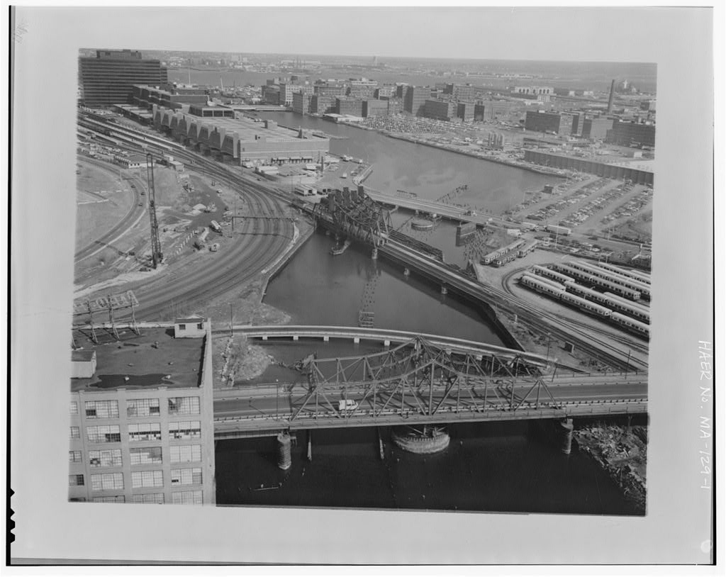
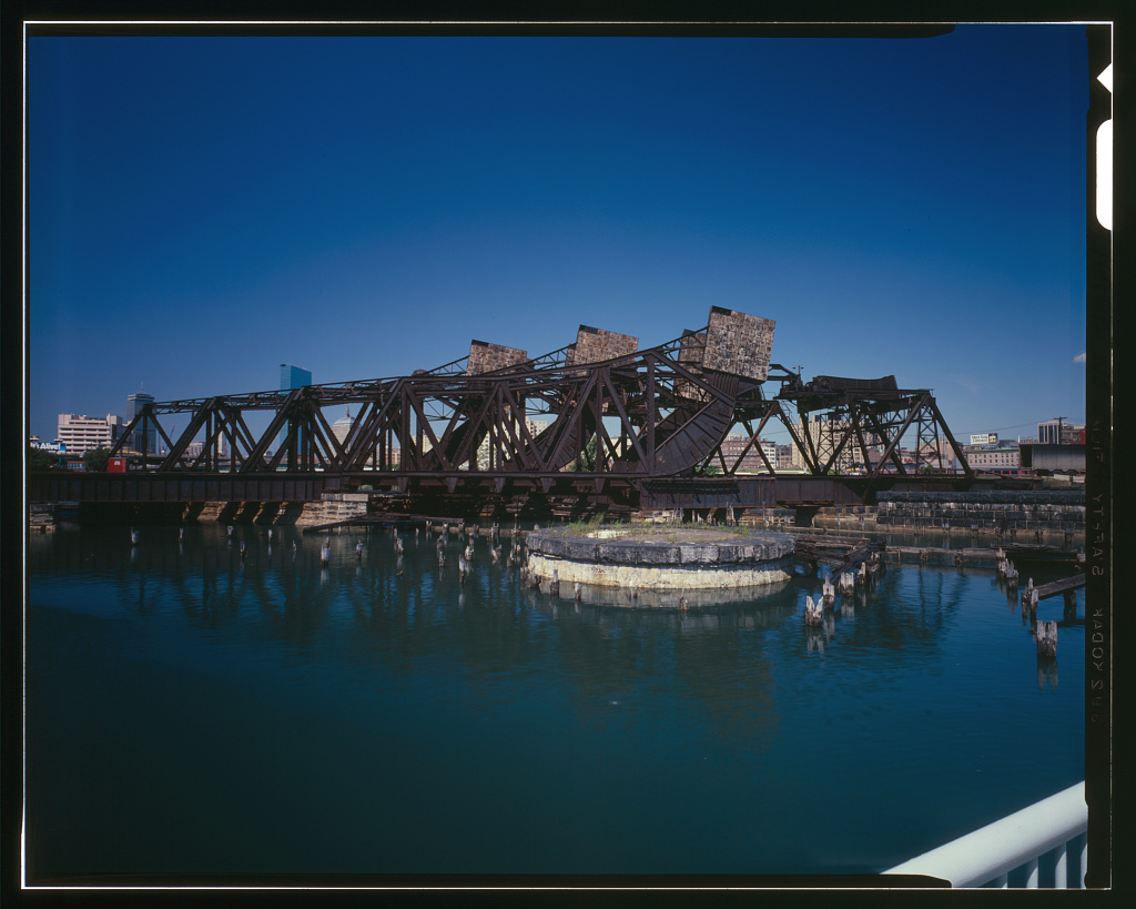
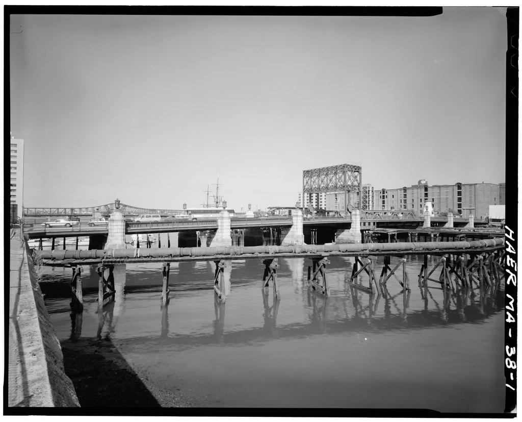
1 This construction was promoted by the reclamation and filling of the area by the Commonwealth for industrial and commercial development in the last quarter of the nineteenth century, culminating in the construction of the Commonwealth and Fish Piers in The railroad, attracted to the waterfront by the Wharf Company in the began a large rail yard in the which became the New York, New Haven and Hartford Railroad's principal Boston freight depot in The existing row of five movable bridges were built across Fort Point Channel between and These include those at Broadway (swing span, South Station Old Colony Railroad Bridge (Scherzer rolling lift,1900, HAER MA-35), Summer Street (paired retractile draw, HAER MA-41), Northern Avenue (Pratt truss swing span, HAER MA-37) and Congress Street (Strauss overhead counterweight bascule, HAER MA-38).2 The Northern Avenue Swing Bridge was constructed during for the City of Boston, under the direction of its Engineering Department, linking downtown Boston on the northwest with the South Boston waterfront on the southeast.
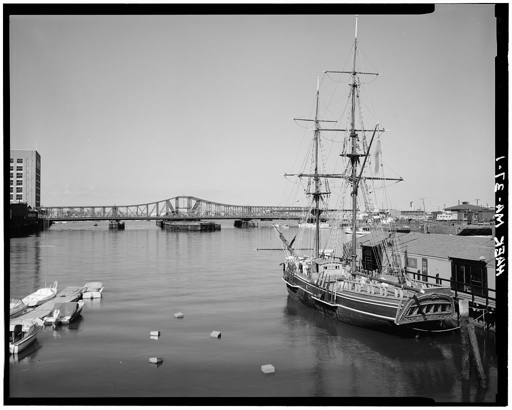
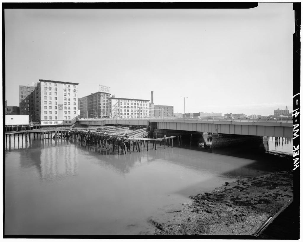
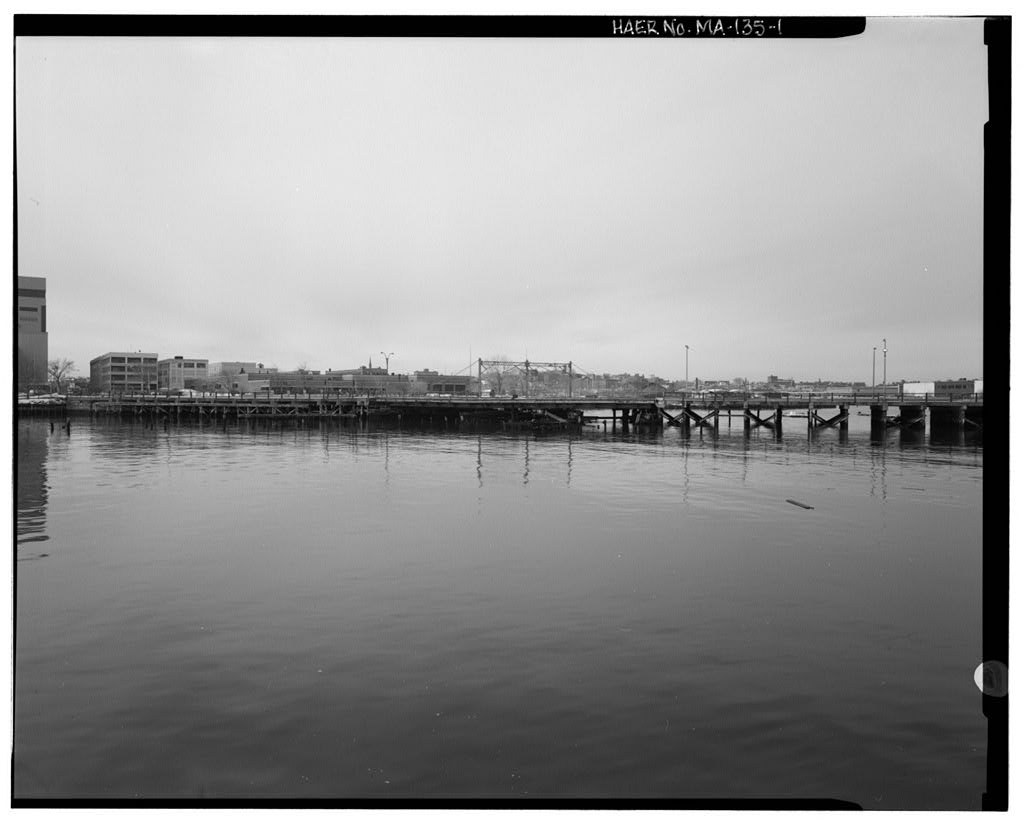
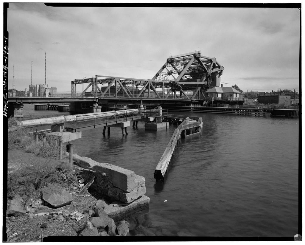
The swing bridge is located on Fort Point Channel between Atlantic Avenue on the northwest and the Fan Pier on the southeast. The swing section is at the center of the bridge and is supported by two polygonal approach span masonry piers and one circular draw span pier between the west abutment and a South Boston pier. The Hook Lobster Company is at the west end and the Neptune Lobster Company at the east end of the bridge on the south or upstream side. On the north side toward the harbor, at the west end is the U.S. Appraiser's Building, and on the east end, the fan pier belonging to Anthony's Pier 4 Inc. 3 Fort Point Channel is a tidal estuary which serves as anchorage for fishing, shellfishing and lobstering vessels as well as pleasure boats and rowing shells.
Boston Harbor is located on the northeast with commercial marinas and businesses, including the Boston Tea Party Ship Museum on the Congress Street Bridge, upstream to the southwest. The Northern Avenue Swing Bridge is the most visible of the five remaining movable bridges on Fort Point Channel, and a principal marine landmark as viewed from Boston Harbor. The bridge has been determined eligible for listing on the National Register of Historic Places.4 NORTHERN AVENUE SWING BRIDGE HAER No.
MA- 37 (page 4) Construction and Alterations The entire history of the Northern Avenue Swing Bridge, including its original construction, rebuilding, repairs and maintenance are well documented in the collections of the Boston Public Works Department Bridge Division, as well as the Annual Reports of the earlier City Engineer's Department, Bridge and Ferry Division, and other photographic collections such as those of the Boston Public Library, the Bostonian Society, and the archives of the Boston Herald. The original and existing conditions of both the site and the bridge are documented by the drawings and photographs accompanying the following text. Additional photos and drawings appear in published sources cited in the bibliography.
The Northern Avenue Swing Bridge, the first crossing at this site, was preceded by earlier structures at the other four bridge crossings along Fort Point Channel, the nearest of which is the Congress Street Bascule Bridge. Northern Avenue's compressed-air movable bridge was built according to the design precedent (and with some interchangeable parts) of the North Washington Street Charlestown Bridge which was constructed under the direction of the city engineers in across the entrance to the Charles River at the North End of the city.
The Northern Avenue Swing Bridge, a triple-barrelled swing bridge with a Pratt-type truss and two similar approach spans, was constructed in as part of a general upgrading of vehicular, railroad and pedestrian service to the South Boston wharfs and warehouses which were expanding at a rapid rate. 5 The existing swing bridge has undergone several repairs and alterations as follows: (ca.) -Track laid over bridge by Union Railway, as originally planned. - Draw pier concrete and masonry repaired; new compressed air tanks. Bridge draw pier, foundation, and draw superstructure rebuilt with minor modifications; new air compressor installed (original retained as backup). End lifts repaired. 6 - Redecking of approach span 3. Railroad track abandoned. - Approach and draw spans redecked.
- Approach span deck bracing repairs; new draw span compressor installed to replace compressor; original compressor functioning as backup. General maintenance over the years has included painting and miscellaneous minor repairs such as installation of steel patch plates; machinery, gate and railing repairs; and grouting of the mortar joints in the granite piers. 7 NORTHERN AVENUE SWING BRIDGE HAER No. MA- 37 (page 5) Key Individuals The bridge was designed by the City Engineer, William Jackson, based on his earlier design of the Charlestown Bridge for which John E. Cheney was Assistant Engineer. The widely utilized Pratt truss used in the bridge's construction was originally patented in by Boston Assistant City Engineer, T. Willis Pratt. The W. H. Ellis Co.
built the masonry piers and abutments and the New England Structural Company of Everett, Massachusetts built the superstucture which was completed in In Ellis & Son Co. repaired the draw fender and fender guards, while A.G. Tomasello & Son Co. repaired the drawbridge masonry pier. In Rideout Chandler & Joyce installed eight new compressed air tanks, piping and valves. The major work of the rebuilding was performed by Gaddis, under the direction of Worcester & Co., Consulting Engineers; new steelwork was fabricated by the Lehigh Structural Steel Co. In the end lifts were repaired by the Boston Bridge Works. Other Boston Public Works Department engineers worked on bridge alterations in the succeeding years, including John J. McCall, Division Engineer, who superintended the repairs.
More recent repairs have been done under the direction of Universal Engineering Corporation, and most recently STV/Seelye Stevenson, Value and Knecht, Lawrence J. McCluskey, P.E., Senior Vice-President. In the past decade Balfour Engineering Co. Inc. and recently their mechanic, Dave Rowell, have executed repairs and provided mechanical services to keep the bridge in operating condition. 8 Construction Techniques - Technical Description Found.ations - The granite masonry piers were built on concrete footings which rest on wood pilings below the river bed.
The westerly abutment on the Boston side is a composite masonry structure, consisting of a front pier on a Portland Cement concrete foundation supported ~y piles and five lines of longitudinal piers which extend back to the face of the old dock wall and support steel I-Beams which carry concrete arches. The easterly abutment on the South Boston side was constructed over the site of a granite seawall built in the mass of large granite blocks was consolidated with concrete since its removal for the driving of piles was not possible. The two channel piers which support the draw ends are curved on the draw-side face to approximate the arc of the end of the draw span swing which rests upon it when the draw is closed.
The center draw pier has a circular concrete foundation resting on wood piles; the concrete of this and other piers was formed by splined plank caissons. The draw fender pier, comprised of oak wood piles braced and partially decked with hard pine, was the largest ever built by the city at the time of its construction. The pier measured from the center of the bridge 290 feet downstream, 215 feet upstream, and 88 feet across. The extension of the triangular ends, 44 feet measured along the center line, made the total length of the draw fender pier 593 feet. Superstructure - The Northern A venue Swing Bridge employs a riveted steel frame on both the approach and the draw spans.
The active leaf of the bridge is a triple-barrelled pinned through-truss swing bridge with a flat-topped single-panel tower. Approach spans 1 and 2 are similar through- truss spans each with four pin-connected trusses about 150 feet long, spaced at 22 foot-eight inches NORTHERN AVENUE SWING BRIDGE HAER No. MA- 37 (page 6) on center. These support three roadways and two outboard cantilevered sidewalks. Span 3, which formerly carried a freight-railway track transversely across the bridge near the South Boston abutment, is a deck plate girder span made up of six plate girders at fourteen feet-nine inches on center with an average length of 55 feet.
The approach span floor paving, resting on six-inch hard pine plank covered with waterproofing and sand, originally consisted of six-inch granite blocks laid with pitch and pebble joints. Sidewalks were originally of four inches of asphalt laid on four-inch thick plank. The 283 feet long by 80 feet wide draw span, a Pratt-type truss with five sloped upper chords in cantilever arms, is visually continuous to the top of the tower. The steel truss towers provide lateral stability to the swing bridge. Each opposing leaf acts as the other's counterweight upon opening, with the truss towers resting on a turntable. The draw span of the bridge was built in an open position, supported by its wood-pile fender pier, and closed upon completion of the truss and machinery assembly.
When closed, the swing bridge ends are supported on sliding blocks, after the lowering of the end lifts. The draw span roadway was five-inch hard pine plank sheathed with spruce plank, and sidewalks were of two-inch hard pine. Repairs and Alterations - A fireboat house and public landing pier were added to the north side of the South Boston approach span circa This auxiliary structure, visible in older views, disappeared within the last decade when it collapsed into the Channel. The two side spans were built originally to accommodate vehicular traffic, and the center span was constructed to accommodate a freight railway spur as well. The tracks were added ten years after the initial construction ca.1918, and removed in In the Boston Public Works Commissioner, J.A.
Rourke nailed down the first rubber paving tile in Boston on the Northern A venue Bridge, but this innovative technology apparently disappeared with the wood planks in later repavings. In Rideout, Chandler and Joyce installed eight new compressed air tanks, new piping and valves in the Tenders' House. The proximity of salt-water to the draw turntable pit led to its deterioration and eventual reconstruction in On January 26, one of the links connecting the upper chord of one of the center trusses to the draw span tower failed and the adjacent links also parted.
Because of the possibility of a complete collapse, a comprehensive engineering survey was made and it was determined that it would be necessary to entirely dismantle the draw, rebuild the draw pit from grade up and rebuild the drawspan superstructure. At that time the draw span was completely dissassembled in order to rebuild the draw pit with reinforced concrete along the lines of the original design. The draw was then completely rebuilt in its original form with replacement of deteriorated members and some repairs using welded, rather than riveted construction techniques. Worcester & Company, Consulting Engineers, superintended the rebuilding which was done by Gaddis, Contractor. This work on the bridge was carried on as a W.P.A. Project which provided federal funding for the rebuilding.
The structure was rebuilt using the old floor beams, truss posts and minor members of the drawspan, and included repairing the fixed spans and redecking of the entire structure. New steelwork of the superstructure, fabricated by the Lehigh Structural Steel Company of Allentown, Pennsylvania, very nearly duplicated the original design as there are no apparent visual differences before and after rebuilding. The original roadway gates remain with some later repairs. NORTHERN AVENUE SWING BRIDGE HAER No. MA-37 (page 7) The wood decking of the draw span, covered with rubber tile pavement in said to be "the first in Boston", has since been replaced with open steel grate decking; the granite block paving of the approach spans has likewise been superseded by asphalt pavement.
The wood fender piers and Draw Tenders' house have deteriorated in intervening years, although they retain much of their original form. Recent repairs have included replacement of the Pennsylvania Compressor with an A. C. powered Joy compressor in although the original Union Steam Pump, made in Battle Creek Michigan in still operates under power with a rectifier, as a backup. The bridge is presently in a somewhat deteriorated state, and requires constant repairs; its inventory rating (type of 30 tons has been reduced to (type 15 tons.8 Description and Operation The three-barren bridge has a steel superstructure which rests on granite block piers and abutments; these in turn are supported by the concrete foundations and friction piles.
The Northern Avenue Swing Bridge consists of three spans: the two approach spans are fixed, paved-deck, steel through-girders averaging 145 feet, each carrying steel stringers. The center draw span is a double- leaf, open-deck steel rim-bearing swing bridge which is 283 feet in length from end to end. The deck width is eighty feet (out to out) and now consists of two vehicular lanes in each barren and two cantilevered sidewalks projecting outboard. The approach spans are paired, pinned Pratt through trusses with vertical end posts. There is no upper lateral bracing between the two inner lines of trusses. The center draw span has lateral bracing among all four Pratt truss lines.
The center tower, 46 feet high measured from the bridge deck, carries the weight of the two independent 125 feet 2 inch swing spans to eight points on a circular drum, 40 feet in diameter. The draw weighs about tons and rests on fifty-six steel wheels running between steel-faced tracks. The total length of the bridge is 643 feet from abutment to abutment. The minimum horizontal clearance through each of the two channel ways of the draw is 75 feet between fenders; the vertical 9learance is 7 feet from mean high water to bottom of steel, and unlimited when the bridge is open. The bridge is operated by a draw tender to allow the passage of boats, with assistant tenders manning the gates and end lift blocks.
The original operating mechanism (rebuilt in similar form in consists of a rim-bearing turntable track and wheels with a rack-and-pinion drive system powered by compressed air. The concrete turntable pit contains the forty foot diameter drum which turns on fifty-six steel wheels running on tracks supported by granite blocks. The operating mechanism consists of a system of donkey engines driving turntable rack-and-pinion gears and plunger-actuated lever-action end lifts, all driven by compressed-air. The compressors in the Tenders' House on the fender pier are powered by direct current electric motors; the compressed air is stored in eight tanks located in an adjoining room.
A manual drive system was designed for use in operating both the revolving mechanism and the end lifts, in the event of electrical failure. Power for draw machinery operation was originally provided by two double-stage compressors each geared to a 50 horsepower electric motor using 500 volt direct current. The operating air pressure was kept at 200 pounds per square inch, with the compressors automatically started or stopped upon fifteen pounds pressure deviation from normal. The eight original steel NORTHERN AVENUE SWING BRIDGE HAER No. MA- 37 (page 8) receiver tanks had a combined capacity of cubic feet.
A four inch pipe main carried the air to the draw span center, directly under the operator's stand; from there the air is delivered at 200 pounds pressure to the end lifts, and at 70 pounds to the donkey engines which turn the draw. The draw is opened by two 6 1/4 inch by 10 inch double-cylinder engines with drive trains attached to the draw; the final pinion of each train acts on a rack attached to the track on the draw pier. These two sets of turning apparatus can operate independently and rotate the draw if one is out of service. The eight end lifts, one at each free end of the four truss lines, are each actuated by a piston in a 16 inch diameter cylinder . The plunger rod actuates a lever using a cast-iron block on the stone pier as a fulcrum.
This mechanism raises the free end of the truss approximately five inches to allow bearing blocks to be slid beneath it. The four blocks at each end of the bridge are connected to a shaft operated by a lever from the roadway deck by the gateman. The truss ends are then lowered half an inch onto the bearing blocks, the end lifts released, gates opened, and traffic passes onto the draw. The operator's stand is located at the center of the draw span between the two roadways, where both street traffic and navigation can be observed. Compressed-air power requires about two minutes to fully open the draw while the manual drive requires about twenty minutes. NORTHERN AVENUE SWING BRIDGE HAER No. MA-37 (page 9) Historical Significance a.
Engineering Significance The primary significance of the Northern Avenue Swing Bridge is its engineering design. It is the only movable bridge still operating on a compressed air system; one of only two triple-barreled swing bridges in the bridge inventory list, where it is listed as one of nine remaining rim- bearing swing bridges. The original Tenders' House survives with its compressed air tanks and one original compressor intact. A former double-track freight railway ran down the center barrel, making it one of very few multi-purpose bridges designed for horsedrawn and automotive vehicles, trains and pedestrians. It is a prominent structure as seen from Boston Harbor and the ferry landing at nearby Rowe's Wharf on the downtown Boston dockside.
The bridge is an integral part of the proposed Fort Point Channel Historic District and a visual landmark on the Boston waterfront. b. Cultural Significance The bridge has secondary historical associations with the development of South Boston, since the construction of this bridge influenced the progress of commercial construction activity on the South Boston waterfront. Northern A venue's construction was an integral part of the promotion of the area by the Commonwealth which resulted in the building of the Commonwealth and Fish Piers in c. Architectural Significance The design of the bridge and the principles involved in its original construction and operation are significant features.
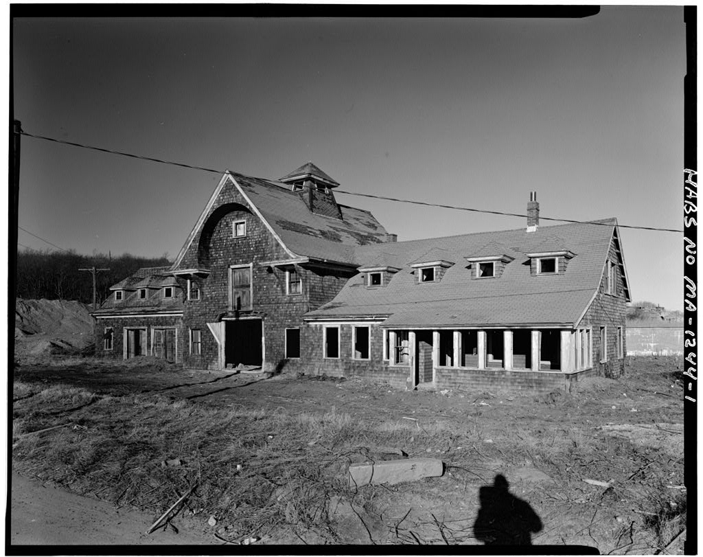
The bridge has less importance from an architectural than from an engineering standpoint; however, the original approach span trusses remain intact and the draw span retains its original graceful appearance visually. The Tenders' House is a good example of the shingle style which enhances the waterfront character of the area. The bridge is a familiar landmark to Boston Harbor and automobile traffic; and visible from other nearby landmark bridges as well.
Contextual Information The Northern Avenue Swing Bridge was built according to the design precedent (and with some interchangeable parts) of the North Washington Street Charlestown Bridge which was constructed under the direction of the City Engineers in Some of the operating machinery of the draw span for the Northern Avenue Bridge was identical to that of the Charlestown Bridge when originally constructed. Most notable was the gearing, made according to Holyoke Machinery Company Patterns, which was noted on drawing number in February of as "interchangeable with the Charlestown Bridge". Recent interviews with bridge tenders, mechanics and engineers reveal that these gears from the Charlestown Bridge were actually used to repair the Northern Avenue Swing Bridge.
These were subsequently replaced when they were in turn destroyed by a tugboat which was being used to close the bridge which had jammed. One original NORTHERN AVENUE SWING BRIDGE HAER No. MA- 37 (page 10) electrically powered air compressor continues to serve the bridge, functioning in a backup capacity since making this the only movable bridge of its type to remain functioning under its original compressed air system. The bridge was the subject of a recent study by Todd Lee/ Clark/ Rozas Associates, Inc. Nonhern Avenue Bridges Study, for the Boston Redevelopment Authority in May of In this report, the design of a nearby replacement bridge and alternatives for the adaptive reuse of the present bridge were explored, a process which is now continuing.
The Fort Point Channel area was also the subject of a study the same year for the Greater Boston Chamber of Commerce, Physical Change and Programming in and around the Fort Point Channel, a Report of the Fort Point Channel Project. This was followed in March of with a Fort Point Channel Plan Progress Report, issued jointly by The City of Boston, the Fort Point Citizens Advisory Committee and the Boston Redevelopment Authority. NORTHERN AVENUE SWING BRIDGE HAER No. MA-37 (page 11)
Boston Engineering Department Annual Reports, Published by the City of Boston, Boston Public Library. Views of bridge as constructed in Annual Report. Darnell, Victor C., Directory of American Bridge Building Companies, (Washington, Society for Industrial Archeology, Greater Boston Chamber of Commerce, Physical Change and Programming in and around the Fort Point Channel, a Report of the Fort Point Channel Project, M. David Lee, Chairperson, July Inventory of Historic Resources, Central Artery/ Third Harbor Tunnel Agency Review Draft, Massachusetts Department of Public Works, Boston, April, Kyper, Frank.
The Railroad that Came Out At Night (Brattleboro, VT: The Stephen Greene Press, View of Union Freight train on bridge, Roper, Stephen J., Massachusetts Department of Public Works Bridge Inventory, May -October Stott, Peter, Bridge Row, The Drawbridges of Fort Point Channel, unpublished typescript, Boston, June Todd Lee / CJark / Rozas Associates, Inc. Northern Avenue Bridges Study , for the Boston Redevelopment Authority, Boston, May Fort Point Channel Plan Progress Report, issued jointly by The City pf Boston, the Fort Point Citizens Advisory Committee, and the Boston Redevelopment Authority, March U.S. Army Corps of Engineers, General- Conditions Letter of Permission No.
MA-BOSS-487-L- 89, January AR CHIVAL COLLECTIONS Boston Public Works Department, Bridge Division Records, 400 Frontage Road, South Boston, Massachusetts Boston Public Library, 666 Boylston Street, Boston, Massachusetts Government Records, Print Department STV/Seelye Stevenson Value & Knecht, Engineers and Planners, 230 Congress Street, Boston, Massachusetts Engineering Files. NORTHERN AVENUE SWING BRIDGE HAER No. MA- 37 (page 12) 1 Inventory of Historic Resources, South Boston, pp. 59 - 66. 2 Stott, Peter, Bridge Row. The Drawbridges of Fort Point Channel. pp 3 U.S.
Army, General Conditions of Corps of Engineers, Attachment Maps 4 Roper, Stephen J., Massachusetts DPW Bridge Inventory, Survey Form, May 5 Boston Engineering Department Annual Reports, - 6 Boston Engineering Department Annual Reports, 7 Boston Public Works Department, Bridge Division Records, STY/Seelye Stevenson Value & Knecht, Engineers and Planners, Engineering Files. 8 Boston and Massachusetts Public Works Departments, Bridge Division Records. , ' ,, ', '' ~~ '' ' ~~ ~~ -~ ~> ~< ~~ trl en ~ ~ t:d ~~ Location Plan USGS Boston South - UTM Zone 19 Massac.i.usetts Department of Mass. DPW oo Public Works -o ~ trl c- : : ~. ] .. ~ --. "' - . ,;. .keno,,, eo,,.,,,c ' ,. - - --- . -.- >, ~ - #' - --- ~ i ., I #M~I 1~ :K K K KA A A ~ - - __ ~'. . ' :; - I ) I ...
~, ~ \, t.I, ~ - \ ., j \ ~ -; \ ~ ij J\ordzc.rn. t I ..: -~ i :: I ~ .,, i ~ Oc:lW,v " " '" ~6 ~~ ~~ z trj ?~ Ol"~N- 111S1N~O~&N1!,,.. ~> \ ,, ., ., - '!- ... . . NO/'ITHOfN AvENUC 8/'IIDGe.. >< . ... -~ ItI1 P_i.AN OI" LOCATION :ja tI1 1= ... 1 1~ . . 'I , ,, J l 1 J . , ' ' , r . .._ 1~~ ; ~- - ; ; : ~ . ' : , -, , ,~ ~! 1, -~~~-~~-~~"":#':,I,,;, I,:;,, I,~;,, I-~~-, I,,-;",, I I ~ I,;,, I ,~~ I~:~. -to I Also Section and Borings Boston Engineering DepL is a MA-37-54 Plan of Location BostonPWD 10 / ~ tT1 William Jackson, City Engineer NORTHERN AVENUE SWING BRIDGE HAER NO. MA.-37 Iloston Public Works Department, Bridge Division LIST OF ORA WINGS (Page 15) .ll.il.u: No, Drawing IitJe { Descrjptjon Agency Engineer Seawall Dock #1 General Plan Boston Engineering Dept.
Seawall Dock #1 Cross Section & Details Boston Engineering Dept Land Plan of Docks Boston Engineering Dept 2&3 Sanding on Dock 2 & 3 Boston Engineering Dept. Seawalls Dock 2 & Bulkhead Easterly from Boston Engineering Dept. Wall Seawalls Docks 2 & 3, Bulkhead @ Pier 3 Boston Engineering Dept. Seawalls Docks 2 & 3, Details of wall @ Boston Engineering Dept. Dock2 . Proposed Grades Northern Ave. Boston Engineering Dept Land Plan for Northern Ave. & Sleeper St Boston Engineering Dept Plan of Location Also Section and Borings Boston Engineering Dept. MA-37-54 William Jackson, City Eng. General Plan Steel Superstructure - Includes Half Sections, Tower, Boston Engineering Dept MA-37-56 Draw Span End,Drum William Jackson, City Eng.
Steel Superstructure - Draw Span Truss Al, Section 2, Changes Boston Engineering Dept William Jackson, City Eng. Steel Superstructure - Draw Span Truss Al - Section 3, Changes Boston Engineering Dept William Jackson, City Eng. Steel Superstructure - Draw Span Truss Al, Section 1, Changes Boston Engineering Dept William Jackson, City Eng. Steel Superstructure - Draw Span Truss B - Section 1 Corrections Boston Engineering Dept William Jackson, City Eng. 3<i62 Steel Superstructure Draw Span Truss B - Section 2 Boston Engineering Dept. William Jackson, City Eng. Steel Superstructure - Draw Span Truss B - Section 3 Boston Engineering Dept MA-37-59 (Inclined/Tower Posts) William Jackson, City Eng. 3<i64 Steel Superstructure - Draw Span Posts A-a, B-b and H-h Boston Engineering Dept.
William Jackson, City Eng. Steel Superstructure - Draw Span Posts D-d and E-e Boston Engineering Dept. William Jackson, City Eng. 36<i6 Steel Superstructure- Draw Span Posts 1-i, M-m Boston Engineering Dept William Jackson, City Eng. Steel Superstructure - Draw Span Posts N-n,o Boston Engineering Dept. William Jackson, City Eng. Steel Superstructure - Draw Span Towers Posts G-g and 0-o Boston Engineering Dept MA-37-60 William Jackson, City Eng. NORTHERN AVENUE SWING BRIDGE HAER NO. MA.-37 Boston Public Works Department, Bridge Division LIST OF DRAWINGS (Page 16) 12.il.u: No, Drawjng TitJe t Descrjptjon Agency / Engjneer 3Ci69 Steel Superstructure - Draw Span Towers Truss Chords, Struts Boston Engineering DepL MA-37-58 and Bracing William Jackson, City Eng.
Steel Superstructure - Draw Span End Portal - Corrections Boston Engineering DepL William Jackson, City Eng. Steel Superstructure - Draw Span Inclined Portal and Strut 5 & 7 Boston Engineering DepL William Jackson, City Eng. Steel Superstructure- Draw Span Top Lateral Bracing, Tie Rods Boston Engineering DepL William Jackson, City Eng. Steel Superstructure - Draw Span Bottom Lateral Bracing Boston Engineering DepL William Jackson, City Eng. Steel Superstructure - Draw Span Floor Beams - Brackets Boston Engineering DepL etc. William Jackson, City Eng. Steel Superstructure.- Draw Span Floor Beams F Bracket Boston Engineering DepL Fascia William Jackson, City Eng. Steele Superstructure - Draw Span Stringers Details Rivet ConsL Boston Engineering DepL William Jackson, City Eng.
Steel Superstructure - Draw Span Turntable Girder C and Shoe Boston Engineering DepL Casting William Jackson, City Eng. Steel Superstructure - Draw Span Turntable Girders D & E - Boston Engineering DepL Corrections William Jackson, City Eng. Steel Superstructure - Draw Span Drum - Corrections made Boston Engineering DepL MA-37-66 William Jackson, City Eng. Steel Superstructure - Draw Span Details of Turntable, Boston Engineering DepL MA-37-65 Additions William Jackson, City Eng. Steel Superstructure - Draw Span Framing for Turning Mechanism Boston Engineering DepL William Jackson, City Eng. Steel Superstructure - Spans 1 & 2 General Plan (Poor Condition) Boston Engineering DepL William Jackson, City Eng.
Steel Superstructure - Spans 1 & 2 Truss A2 - Section 1, Shoe Boston Engineering DepL Castings William Jackson, City Eng. Steel Supersturcture - Spans 1 & 2 Truss A2 - Section 2, (Tie Bars) Boston Engineering DepL William Jackson, City Eng. Steel Superstructure - Spans 1 & 2 Truss B2- Section 1 Portals Boston Engineering DepL (Rollers) Changes William Jackson, City Eng. Steel Superstructure - Spans 1 & 2 Truss B2 - Section 2, Changes Boston Engineering DepL William Jackson, City Eng. Steel Superstructure - Spans 1 & 2 Truss B2, Section 3, Top Lateral Boston Engineering Dept. Bracing William Jackson, City Eng. Steel Superstructure - Spans 1 & 2 Middle floor Beams, changes Boston Engineering DepL William Jackson, City Eng.
Steel Superstructure - Spans 1 & 2 Side Floor Beams & Brackets Boston Engineering DepL William Jackson, City Eng. Steel Superstructure - Spans 1 & 2 Roadway and Track Stringers - Boston Engineering DepL Changes William Jackson, City Eng. NORTHERN AVENUE SWING BRIDGE HAER NO. MA.-37 Boston Public Works Department, Bridge Division LIST OF DRAWINGS (Page 17) ll..il.JJ: !Sa, llcall'.iD2 IUII: l ll1:1ii:cl12li12D ~ 421:Dl:I ED2iDl:l:C (General) Draw Span and Fixed Spans Sections of Floor - "For Design Boston Engineering Dept. MA-37-55 See Final Plans for Modifications" William Jackson, City Eng. Proposed Bridge Boston Engineering Dept. William Jackson, City Eng. Profile on North Curb Line Boston Engineering Dept. William Jackson, City Eng. South Boston Abutment Boston Engineering Dept.
William Jackson, City Eng. Piers & Abutments Details Pier 3 Boston Engineering Dept. William Jackson, City Eng. Piers & Abutments Details Piers 1 & 2 Boston Engineering Dept. William Jackson, City Eng. Course Plans Piers .1, 2, 3 Boston Engineering Dept. William Jackson, City Eng. Details of Boston Abutment Piers & Abutments Boston Engineering Dept. William Jackson, City Eng. Details of Boston Abutment Piers & Abutments Boston Engineering Dept. William Jackson, City Eng. Pier & Abutments Details of Draw Pier Foundation Boston Engineering Dept. William Jackson, City Eng. Details of Draw Pier Foundation above Grade Boston Engineering Dept. 0 William Jackson, City Eng. Bearing Stones for Turntable Track Boston Engineering Dept. William Jackson, City Eng.
Draw Fender Pier Details Piers & Abutments (2) Parts Boston Engineering Dept. William Jackson, City Eng. Draw Fender Pier Platform around Center Pier Boston Engineering Dept. William Jackson, City Eng. Draw Fender Pier General Plan & Sections Boston Engineering Dept. William Jackson, City Eng. Draw Fender Pier Plan & Section of Timbering Boston Engineering Dept. William Jackson, City Eng. Proposed Location Power Plant Boston Engineering Dept. William Jackson, City Eng. _Location & Grades of Bearing Plates & Boston Engineering Dept. Castings William Jackson, City Eng. Diagram Showing Distributions of Loads on Boston Engineering Dept. Draw Turntables William Jackson, City Eng. Steel Superstructure Draw Span Boston Engineering Dept. Truss Al Sec. 1 William Jackson, City Eng.
Steel Superstructure Draw Span Detail Top Chord Joint B Truss A Boston Engineering Dept. William Jackson, City Eng. Steel Suprstructure Draw Span Detail Top Chord Joint I Truss B 1 Boston Engineering Dept. William Jackson, City Eng. NORTHERN AVENUE SWING BRIDGE HAER NO. MA.-37 Boston Public Works Department, Bridge Division LIST OF ORAWINGS (Page 18) No, Drawjng IWe I Description Agency f Engineer Steel Superstructure Draw Span Slotted Hole in Chord F-G Truss A Boston Engineering Dept. William Jackson, City Eng. Steel Superstructure Draw Span Slotted Hole in Choid N-0 Truss B Boston Engineering Dept. William Jackson, City Eng. Assembly Drawing Showing End of Draw & With relation to Piers 1 & 2 Boston Engineering Dept. Fixed Span Truss B William Jackson, City Eng.
Steel Superstructure Spans 1 & 2 Castings at Fixed ends of Trusses Boston Engineering Dept. William Jackson, City Eng. Fixed Span General Plan Boston Engineering Dept. William Jackson, City Eng. Railing Boston Engineering Dept. William Jackson, City Eng. General Arrangement of Gates & Details Boston Engineering Dept. Burner Posts William Jackson, City Eng. Gates & Castings Pins Details Boston Engineering Dept. William Jackson, City Eng. Gates & Castings Pins Details Boston Engineering Dept. William Jackson, City Eng. Stress Sheet Fixed Span Boston Engineering Dept. William Jackson, City Eng. Arrangement of Bars Draw & Fixed Spans Boston Engineering Dept. William Jackson, City Eng. Steel Superstructure - Span 3 General Plan Boston Engineering Dept. William Jackson, City Eng.
Steel Superstructure - Span 3 GirderK Boston Engineering Dept. William Jackson, City Eng. Steel Superstructure - Span 3 GirderL Boston Engineering Dept. William Jackson, City Eng. Steel Superstructure - Span 3 GirderM Boston Engineering Dept. William Jackson, City Eng. Steel Superstructure - Span 3 GirderN Boston Engineering Dept. William Jackson, City Eng. Steel Superstructure - Span 3 GirderO Boston Engineering Dept. William Jackson, City Eng. Steel Superstructure - Span 3 GirderP Boston Engineering Dept. William Jackson, City Eng. Steel Superstructure - Span 3 GirdersL&O Boston Engineering Dept. William Jackson, City Eng. Steel Superstructure - Span 3 Side Floor Beams - Sidewalk Boston Engineering Dept. Brackets William Jackson, City Eng.
Steel Superstructure - Span 3 Skew Floor Beams and Bracket Boston Engineering Dept. William Jackson, City Eng. Steel Superstructure - Span 3 Stringers Boston Engineering Dept. William Jackson, City Eng. NORTHERN A VENUE SWING BRIDGE HAER NO. MA.-37 Boston Public Works Department, Bridge Division LIST OF DRAWINGS (Page 19) ~ No, Drawjng Tjtle t Descrjptjon ~ Agency I Engineer Steel Superslructure - Span 3 Fascia - (Rail Detail) Boston Engineering DepL William Jackson, City Eng. Steel Superslructure- Span 3 Lateral Bracing Boston Engineering DepL William Jackson, City Eng. Flooring General Plan Details of Paving and Boston Engineering DepL MA-37-61 Waterproofing- Revisions William Jackson, City Eng.
Flooring - Draw Span Spruce Plank"+ 1 Mineral Boston Engineering DepL Asphalt William Jackson, City Eng. Timber Flooring Details - Spans 1 & 2 "Superceded" - "Adjusted to Fit" Boston Engineering DepL William Jackson, City Eng. Flooring - Span 3 "Wooden Underflooring" Boston Engineering DepL William Jackson, City Eng. Details of Island ends Boston Engineering DepL William Jackson, City Eng. Boston Abutment Course Plan Boston Engineering Dept William Jackson, City Eng. Details of Drain Pipes Boston Engineering DepL William Jackson, City Eng. Span 3 Boston Engineering DepL William Jackson, City Eng. Layout Span 3 Boston Engineering DepL William Jackson, City Eng. Boston Approach Line & Grade Boston Engineering Dept William Jackson, City Eng.
Ballast & Filling @ Dock #1 Boston Engineering Dept William Jackson, City Eng. East of Sleeper SL to Commonwealth Grades for Const Part 1 Boston Engineering DepL Lands William Jackson, City Eng. East-of Sleeper SL to Commonwealth Grades for ConsL Part 2 Boston Engineering DepL Lands William Jackson, City Eng. East of Sleeper SL to Commonwealth Grades for ConsL Part 3 Boston Engineering Dept Lands William Jackson, City Eng. Cross Section - Draw Title - "Northern Avenue Draw" Boston Engineering DepL MA-37-57 William Jackson, City Eng. General Plan Operating Machinery, Draw Elevation /Section Details Boston Engineering DepL MA-37-62 Span, Piping/Air Cylinders at End Lifts William Jackson, City Eng. Feneral Arr. Op. Mach.
Draw Piping Levers, Sheet Superceded Boston Engineering DepL Valves, etc. at Center William Jackson, City Eng. Operating Machinery, Draw Span, Arrange- Mar. 11: "This sheet supercedes Boston Engineering DepL MA-37-63 ment of Piping, Levers, Valves, etc. at Centre sheet No.2 dated Feb. 15, Boston Engineering DepL Oper. Mach. Draw Span, Spring Joints, Boston Engineering DepL Levers, and Stands, etc. William Jackson, City Eng. Operating Machinery - Draw Span Air Brake, Gearing, Boston Engineering DepL MA-37-67 General Plan Turning Mechanism William Jackson, City Eng. NORTHERN A VENUE SWING BRIDGE HAER NO. MA.-37 Boston Public Works Department, Bridge Division LIST OF DRAWINGS (Page 20) ~ No, Drawjng IitJe t Pescrjptjon Agency I Eugiueec Oper. Mach.
Rack and Pinion for Turntable Boston Engineering Dept. William Jackson, City Eng. Oper. Mach. Part Plan/Elev. Shafting and "Removed Boston Engineering Dept. Levexs on Fixed Spans William Jackson, City Eng. Op ating Machinery- Draw Span General Plans of End Lifts - Boston Engineering Dept. MA-37-64 Trusses Bl William Jackson, City Eng. Operating Machinery - Draw Span General Plans of End Lifts - Trusses Boston Engineering Dept. Al William Jackson, City Eng. General Plan/Details - Draw Centering Device "Not Used" (in pencil) Boston Engineering Dept. William Jackson, City Eng. Cross Sections Showing Grading Boston Engineering Dept. William Jackson, City Eng. Cross Sections Showing Grading Boston Engineering Dept. William Jackson, City Eng. Catch Basin Boston Engineering Dept.
William Jackson, City Eng. Operating Machinery Draw Span Details of Turning Mechanism Boston Engineering Dept. William Jackson, City Eng. Op ating Machinery Draw Span Air Cylinders for End Lifts Boston Engineering Dept. William Jackson, City Eng. Operating Machinery Draw Span Pedestals, Blocks & Castings for Boston Engineering Dept. End Lifts William Jackson, City Eng. Op ating Machinery Draw Span Levers, Links & Shafting for End Boston Engineering Dept. Lifts William Jackson, City Eng. Operating Machinery Draw Span Framing for Air Cylindexs Boston Engineering Dept. William Jackson, City Eng. Operating Machinery Draw Span General Plan & Details of Boston Engineering Dept. Emergency Lifts William Jackson, City Eng.
Operating Machinery Draw Span Plan & Section of Re- ceiver of Boston Engineering Dept. Power Rooms William Jackson, City Eng. Receivers for Power Plant Boston Engineering Dept. William Jackson, City Eng. Structure over Center & Frame for Supporting Operating Machinery Boston Engineering Dept. Receivers William Jackson, City Eng. Plan & Section of Flooring Inside Drum Operating Machinery Boston Engineering Dept. William Jackson, City Eng. Ladders & Changes for Machinery Draw Boston Engineering Dept. William Jackson, City Eng. Details of Platform @ Piers 1 & 2 Boston Engineering Dept. William Jackson, City Eng. Details of Housing over Operating Valves Boston Engineering Dept. William Jackson, City Eng. Fences on Docks 1, 2, 3 Boston Engineering Dept. William Jackson, City Eng.
NORTHERN AVENUE SWING BRIDGE HAER NO. MA.-37 Boston Public Works Department, Bridge Division LIST OF DRAWINGS (Page 21) ll..ilJ.c No, Drawjng IUJe t Pescrjptjon Agency t Engineer Proposed Ferry Landing off Sleeper SL Boston Engineering Dept Public Landing for Boats Proposed Boston Engineering Dept Public Landing for Boats Proposed Boston Engineering Dept Berth for Fire Boat Boston Engineering Dept. Wharf & Pier for Fire Boat Boston Engineering Dept. Prop Extension of Fender Guard Boston Engineering Dept Wharf &Pier Boston Engineering Dept. For Fire Boat House Boston Engineering Dept Draw Span Operating Machinery Boston Engineering Dept Piston for End Left Cylinders William Jackson, City Eng. Public Boat Landing Both Summer & Northern Ave. Boston Engineering Dept.
Public Boat Landing Both Summer & Northern Ave. Boston Engineering Dept. Public Boat Landing Both Summer & Northern Ave. Boston Engineering Dept. Electrical Signals for End Lifts Boston Engineering Dept. Draw Centering Device Alternative Design Boston Engineering Dept Repairs on Bottom Chord Span 1 Boston Engineering Dept Repairs on Bottom Chord Span 1 Boston Engineering Dept Repairs on Draw Span Boston Engineering Dept Navigation Light, Ladders & Platforms Sheet Boston Engineering Dept. 2 Navigation Light, Ladders & Platform Sheet 1 Boston Engineering Dept. Prop Additional Piling in Draw Fender Boston Engineering Dept. Repairs for Air Compressor Boston Engineering Dept. Foundation for ~ Compressor Boston Engineering Dept. NORTHERN AVENUE SWING BRIDGE HAER NO.
MA.-37 Boston Public Works Department, Bridge Division LIST OF DRAWINGS (Page 22) 12.iw: No. Drawing Title I Descrjptjon Agency I Engineer Changes in Draw Fender Pier for Addition to Boston Engineering Dept. Tenders House Strengthening compressor Foundation Boston Engineering Dept. Resetting Draw Track Piles for Supporting Boston Engineering Dept. Ends of Draw Alterations & Additions to Power Plant & Boston Engineering Dept. Tenders House Wharf & Pier for Fire Boat Plans Showing Additons & Repairs Boston Engineering Dept. Compressor Foundation Boston Public Works Dept. Bridge Division Steel Face for Compressor Gear Boston Public Works Dept. Bridge Division Compressor Circulating Water Returns to Boston Public Works Dept.
Emergency Tank Bridge Division Arrangement of Piping & New Steel Tank for Boston Public Works Dept. Compressed Air Bridge Division 2764A Tanks for Compressed Air Boston Public Works Dept. Bridge Division Crib - Actual & Theoritical Positions Boston Public Works Dept. Bridge Division Operating Machinery, Details of Fulcrum Boston Public Works Dept. Springs Bridge Division Proposed Alterations of Air Piping near Boston Public Works Dept. Centre Bridge Division Modification of Shoes Boston Public Works Dept. Bridge Division Iron Ladder set in Face of Draw Fender Pier Boston Public Works Dept. Bridge Division Boxing for Electric Heater Over Sump inside Concrete Draw Boston Public Works Dept. Pier Bridge Division Sump inside the Concrete Draw Pier Boston Public Works Dept.
Bridge Division .Fence around Draw Pit Boston Public Works Dept. Bridge Division Rebuilding Pit of Draw Pier Boston Public Works Dept. Bridge Division m Borings Boston Public Works Dept. Bridge Division Draw Span Top Lateral Bracing@ Tower & Boston Public Works Dept. Framing @ Fnd Lifts Bridge Division Draw Span Repairs Details of Pedestals, Blocks, Boston Public Works Dept. Castings, End Lifts Bridge Division NORTHERN A VENUE SWING BRIDGE HAER NO. MA.-37 Boston Public Works Department, Bridge Division LIST OF DRAWINGS (Page 23) .12.DJ.i: No. Drawing TltJe t Description Agepcy t Rpgjpeer Draw Span Electrically Operated Machinery Boston Public Works Dept. for Sliding Blocks Bridge Division Electric Equipment Layout Wiring & Details On Pier S Boston Public Works Dept.
Bridge Division Electric Equipment Layout Wiring & Details On Super Structure Boston Public Works Dept. Bridge Division Draw Span General Arrangement of Piping & Boston Public Works Dept. Operating Machinery Bridge Division Draw Span Prop Arrangement of Air Pipes & At Air Receivers in Power House Boston Public Works Dept. Centring Cylender Bridge Division Draw Span Prop Arrangement of Air Pipes & At Center of Draw Span Boston Public Works Dept. Controls Bridge Division GirderF5 Lehigh Structural Sheet Co. Boston Public Works Dept. Bridge Division Bottom Lateral Bracing Boston Public Works Dept. Bridge Division (UlO Bottom Lateral Bracing Boston Public Works Dept. Bridge Division (Ull Bottom Lateral Bracing Boston Public Works Dept.
Bridge Division Bottom Lateral Bracing Boston Public Works Dept. Bridge Division (U73 Girders T5A, CR, CL Boston Public Works Dept. Bridge Division (U74 Steel Super Structure Draw Span Boston Public Works Dept. Bridge Division Pin Diameters Boston Public Works Dept. Bridge Division 6976A Steel Super Structure Spans 1 & 2 Boston Public Works Dept. Bridge Division (U16 Steel Super Structure Top Chord Shop Boston Public Works Dept. Spliters Bridge Division Steel Super Structure Draw Span Boston Public Works Dept. Bridge Division (U18 Steel Super Structure Draw Span Boston Public Works Dept. Bridge Division Steel Super Structure Draw Span Boston Public Works Dept. Bridge Division Steel Super Structure Draw Span Boston Public Works Dept.
Bridge Division Steel Super Structure Draw Span Boston Public Works Dept. Bridge Division Steel Super Structure Draw Span Boston Public Works Dept. Bridge Division NORTHERN A VENUE SWING BRIDGE HAER NO. MA.-37 Boston Public Works Department, Bridge Division LIST OF DRAWINGS (Page 24) No, Drawjng IitJe t Descrjptjon Agency t Engineer A Top Chord Mark B Boston Public Works Dept. Bridge Division EndPostAaR Boston Public Works Dept. Bridge Division PostKK Boston Public Works Dept. Bridge Division Pin Elevators Draw On - Draw Off Lower Boston Public Works Dept. Chords Bridge Division Elevators on Center of Truss M Lower Chord Boston Public Works Dept. Bridge Division Redecking Spans - Span 3 Plan and Sections, "Fence" Post Boston Public Works Dept.
Bridge Division Redecking Spans - Span 3 Sections and Details Boston Public Works Dept. Bridge Division 7184A Redecking Span 3 Surface Grades Boston Public Works Dept. Bridge Division Study for Replacement Boston Public Works Dept. Bridge or Culvert Bridge Division Condition Survey Pier 1 T&L Boston Public Works Dept. Bridge Division Condition Survey Pier 2 T&L Boston Public Works Dept. Bridge Division Condition Survey & Repairs Pier 1 DeMarione Boston Public Works Dept. Bridge Division Condition Survey & Repairs Pier 2 DeMarione Boston Public Works Dept. Bridge Division Title Sheet Truss Repair Details Boston Public Works Dept. Bridge Division General Plan - Elevation & Details Truss Repair Details Boston Public Works Dept.
Bridge Division Top Chord & Diagonal Splices Truss Repair Details Boston Public Works Dept. Bridge Division New End Portals Boston Public Works Dept. Bridge Division New End Portals Truss Repair Details Boston Public Works Dept. Bridge Division Method for Temporary Construction Support Boston Public Works Dept. Bridge Division Method for Temporary Construction Support Truss Repair Details Boston Public Works Dept. Bridge Division 6995A 3 I Beam Weld Flooring H. S. Boston Public Works Dept. Bolts Bridge Division Jacking Beam H. S. Bolts Boston Public Works Dept. Bridge Division NORTHERN A VENUE SWING BRIDGE HAER NO. MA.-37 Iloston Public Works Department, Ilridge Division LIST OF DRAWINGS (Page 25) Jl.a1c No, Drawing TitJe t Descrjptjon Agency t Engineer Weld Fillet U.N.
Boston Public Works DepL Bridge Division Reconstruction Draw Span Deck Removal Boston Public Works DepL Bridge Division Reconstruction Draw Span Framing Plan Boston Public Works DepL Bridge Division Reconstruction Draw Span Deck Plan Boston Public Works DepL Bridge Division Reconstruction Approach Spans Removal and Framing Plan Boston Public Works DepL Bridge Division Reconstruction Approach and Draw Spans Deck Plan Boston Public Works DepL Bridge Division Reconstruction Approach and Draw Spans Miscellaneous Detail Boston Public Works Dept.
Bridge Division 6088A Reconstruction Draw Span Deflection Restraining Devices Boston Public Works DepL issued for Construction Bridge Division Decking 5" Weldlock Type "H" Open and Boston Public Works DepL Type "C" Bridge Division Type Fabrication Details of Bridge Flooring Boston Public Works DepL Bridge Division Typical Fabrication Flooring [Decking] 3 1/2 I Beam Weld Flooring 3 Boston Public Works DepL x 3/8 Open type flooring Bridge Division A Location Plan USGS Boston South - UTM Zone Massachusetts Department 19 of Public Works Approach Span Repairs Deck Bracing Repairs, D ~ Boston P W D / Seelye Stevenson Value & Knecht B Photo Key Plan Locates Existing Conditions McGinley-Hart & Associates photograph viewpoints. on Boston PWD base plan.
ADDENDUM TO: HAER MA-37 NORTHERN AVENUE SWING BRIDGE HAER MASS,13-BOST,84- Spanning Fort Point Channel at boundary between Boston & South Boston Boston Suffolk County Massachusetts FIELD RECORDS HISTORIC AMERICAN ENGINEERING RECORD National Park Service U.S. Department of the Interior C Street NW Washington, DC ADDENDUM TO: HAER MA-37 NORTHERN AVENUE SWING BRIDGE HAER MASS,13-BOST,84- Spanning Fort Point Channel at boundary between Boston & South Boston Boston Suffolk County Massachusetts FIELD RECORDS HISTORIC AMERICAN ENGINEERING RECORD National Park Service U.S. Department of the Interior C Street NW Washington, DC
 Block
Block