Boston Elevated Railway, Elevated Mainline, Washington Street, Boston
Boston Elevated Railway, Elevated Mainline, Washington Street, Boston, Suffolk County, MA. Surveyed as HAER MASS,13-BOST,127-, with 1 photograph and a 34,555-word written history.
From the record
“This portion of the Orange Line elevated is historically significant as Boston's first elevated line, built during a period of world-wide interest and experimen- Boston Elevated Railway Company HAER No.”
Written record, HAER MASS,13-BOST,127- survey. Machine-read text.
surveyed by the federal HAER program as HAER MASS,13-BOST,127- · the record runs 34555 words · one of 264 surveyed structures published for this county.
Source document
Quoted word for word from HAER MASS,13-BOST,127-.
Not written, edited or summarised by this site.
The Mainline of the BERy at one time consisted of six sections which traversed the congested areas of Boston and Charlestown to Roxbury and Jamaica Plain. For convenience these sections will be categorized alphabetically, according to their original loca- tions, and hereafter will be referred to by Section letter. The main body of this report concerns Section F. The sections are indexed on plans of the former BERy, MTA and the current MBTA. These plans have been included in this study as Fig. No.
and * * * * This report with the accompanying illustrations was compiled to serve as a mitigatory documentation of this structure in order to comply with the requirements of the Memorandum of Agreement, signed February by the Advisory Council on Historic Preser- vation; Urban Mass Transportation Administration; and the Massa- chusetts State Historic Preservation Officer. * * * *
Section a
Formerly the Charlestown Division of the Boston Elevated Railway Company (BERy). Constructed in Sullivan Square Terminal southerly through Charlestown to the North Portal of the subway. Included City Square, Thompson Square, North Station stations and the Charlestown drawbridge over the Charles River (built in by the Boston Transit Commission). This section was abandoned in and was demolished in when the new Orange Line subway was extended to Medford along Boston Elevated Railway Company HAER No. MA-14 Page 5 the Boston and Maine Railroad right of way. Only Tower "C" was saved from demolition and moved to the Seashore Trolley Museum at Kennebunkport, Maine. SECTION A-l Extension of the Charlestown Division line easterly into Everett.
Con- structed in Included only one station Everett (built by the BERy). Discontinued in and demolished in SECTION B North Portal to Pleasant Street Station (now Broadway) via the outer tracks of the Tremont Street Tunnel which was adapted to elevated train use in by the construction of higher platforms. This link was returned to full streetcar use in with the construction of the Washington Street Tunnel. SECTION C Pleasant Street Station, up the incline, over the Boston and Albany and New Haven Railroad right-of-way tracks, and along Castle Street as an elevated structure, to Tower "D" (Bent on Washington Street. Constructed by the BERy in to link the Washington Street elevated to the South Portal of the Tremont Street Subway.
Abandoned in Demolished in Incline portion remained until demolition in Boston Elevated Railway Company HAER No. MA-14 Page 6 SECTION D Elevated structure along Atlantic Avenue from Tower C at North Station to Tower D at Washington Street. Constructed in and in use until Demolished in SECTION E North Portal to South Portal via Washington Street Tunnel. Built in by the Boston Transit Commission. This section will continue in use after demolition of the elevated structure. SECTION F South Portal to Forest Hills repair shops. This line was originally known as the Roxbury Division of the BERy. The line is divided for identifica- tion purposes into the following sub-sections: SECTION F-l South Portal (Bent to Tower D at Washington Street.
Built in by the BERy to connect the new subway tunnel to the Washington Street line of the Roxbury Division. Structural system is plate girder bents with longi- tudinal plate girders. SECTION F-2 Tower D at Bent to Bent south of Dover Street Station. Built between and as part of the BERy Roxbury Division to Dudley Terminal. Plate girder bents with longitudinal truss girders. Boston Elevated Railway Company HAER No. MA-14 Page 7 SECTION F-3 Bents to along Washington Street. Built between and by the BERy. Includes Northampton Street Station. Arched truss bents with longitudinal truss girders. SECTION F-4 Bents through to the Bartlett Street Yard. Built in to by the BERy as part of the original Roxbury Division.
Includes the Dudley Terminal and the Guild Street yards and repair shops (discontinued in Plate girder bents with longitudinal truss girders. Loop around Dudley Station is marked by Bents T-l through SECTION F-5 This section is the beginning of the Forest Hills Division. Construction work began on May 2, and service began on November 22, Work included rebuilding the loops and platforms at Dudley Street Station and the construction of Egleston Station. Section F-5 runs as an elevated structure from Bent to at the Arborway yards. Construction is plate girder bents with plate longitudinal girders. Green Street Station was added on as a suspended structure in SECTION F-6 This section was a specially designed steel framework encased in concrete. Bents to include Forest Hills Station.
Built in by the BERy. Boston Elevated Railway Company HAER No. MA-14 Page 8 SECTION F-7 Bents through constitute the Forest Hills train storage yards and the repair shops. This extension was built in Repair shops built in Includes Tower This section was demolished in Dates of Construction: Sections F-l through - Sections F-5 through - Section - Engineers/Builders: Boston Elevated Railway Company Engineering Department: George A. Kimball, Chief Engineer
Present Use
64 words
Source document
Quoted word for word from HAER MASS,13-BOST,127-.
Not written, edited or summarised by this site.
Remaining portion of the original BERy elevated Mainline Structure is currently in use as part of the MBTA's Orange Line rapid transit service from Forest Hills to Medford, Mass, The elevated portion (Section F-l through serves from the South End through Jamaica Plain. The entire structure is slated for demolition when the new Southwest Corridor segment of the Orange Line rapid transit is completed.
Significance
32808 words
The headings the report itself prints. Each one jumps to where it begins.
Source document
Quoted word for word from HAER MASS,13-BOST,127-.
Not written, edited or summarised by this site.
This portion of the Orange Line elevated is historically significant as Boston's first elevated line, built during a period of world-wide interest and experimen- Boston Elevated Railway Company HAER No. MA-14 Page 9 tation with elevated railways; and as the product of Boston's last privately-owned transit company, the Boston Elevated Railway Company. Architecturally, it is significant for the quality of its original station architecture, which was designed by the prominent local architect, Alexander Wadsworth Long- fellow. Later alterations were carried out under con- sultation with other leading Boston architects, such as Robert Swain Peabody and Edmund Wheelwright.
In gen- eral, it represented the most advanced transportation planning of its day and is a good case study, on a small scale, of rapid transit at the turn of the century. Historians: Cynthia Zaitzevsky - Consultant in Architectural History to Kaiser Engineers, Inc./Fay, Spofford and Thorndike, Inc. (Coordinating Consultants to the MBTA for design and construction of the new relocated Orange Line -- Southwest Corridor Project) Christine Fernandez Carvajal - Research Assistant Calvin Opitz - Assistant on Structural Engineering Portion Nikita Zaitzevsky - Assistant Boston Elevated Railway Company HAER No.
MA-14 Page 10 BOSTON ELEVATED RAILWAY COMPANY - ELEVATED MAINLINE STRUCTURE (MBTA - ORANGE LINE) Submitted to the HISTORIC AMERICAN ENGINEERING RECORD by Cynthia Zaitzevsky Consultant in Architectural History to Kaiser Engineers, Inc./Fay, Spofford and Thorndike, Inc. Six St. James Avenue Boston, Mass. for Massachusetts Bay Transportation Authority Contributing Authors: Christine Fernandez Carvajal Calvin Opitz Nikita Zaitzevsky The preparation of this report has been financed in part through a grant from the U.S. Department of Transportation Administration, under the Urban Mass Transportation Act of as amended. Boston Elevated Railway Company HAER No- HA-14 Page 11
Table of Contents
Orange Line Documentation Pages Chapter 1 12 Introduction and Discussion of Significance Chapter 2 14 History of Early Public Transportation in Boston Chapter 3 24 Construction of the Elevated Structure - Chapter 4 34 Construction of the Forest Hills Extension Chapter 5 40 Architectural Description of the Stations Chapter 6 50 Structural Analysis and Description of the Elevated Structure Bibliography 63 Appendix A 68 Chronological History of Orange Line up to Appendix 8 74 Description of the Early Electrical Systems (Abstract of Contemporary Description by Frank J. Sprague) Appendix C 84 List of Historical Photographs. Appendix D 212 List of Historic Drawings. Boston Elevated Railway Company HAER No.
MA-14 Page 12 Chapter 1 Introduction and Significance of the Orange Line Elevated Ever since Boston's earliest days Washington Street has been the main route for transportation between Boston and Roxbury and all other towns in the southwest portion of the larger city. The earliest stagecoach followed by the omnibus and later by horse-drawn and then the electric streetcar all used this route that was to become so heavily travelled that by the it had become imperative to build an elevated railway to provide rapid transit north and south of Boston. This section of the elevated structure from Dover Street to Forest Hills is the last remnant of a larger system of elevated railroads that served Boston at the turn of the century.
Boston was one of the last major American cities to build an elevated rapid transit line. The system was developed first in New York City and refined in Chicago, where third-rail electric motive power was first used. Because it was built comparatively late, the Boston Elevated structure could use advanced rapid transit technology borrowed from many different sour- ces. It is today a good case study, on a small scale, of the "State of the Art" of rapid transit at the turn of the century. The Orange Line is significant not only from the point of view of tech- nology but it also represented the most advanced transportation planning of its day. The BERy was the first company in the United States to include subways, elevated transit and surface trolleys -- all operating under one management.
Boston Elevated Railway Company HAER No. MA-H Page 13 In contrast to a system with many competing lines and companies (the usual situation in most cities), the public could transfer from one section to another of the BERy without paying more than one fare. The early history of the Boston Elevated Railway and the Orange Line illustrates how Boston avoided the excesses of both total public control and free-wheeling private enterprise. All major cities building transit systems at that time had such problems in common, but in Boston a balance was struck: private management ran the system but government regulated it and also built the subways. Although it was a small system, Boston's distinctive topography caused many difficult planning and engineering problems.
Narrow curving streets, high den- sity in the downtown area, limited arteries into the center of Boston, the hilly terrain, the Boston Common and Public Garden, and settled residential districts made the task difficult for the Civil Engineer. Contemporary descriptions of the system continually extolled the work. It remains today an impressive under- taking. By studying this system today, we learn on a modest scale about the problems of other transit systems of that era. We can also more fully appre- ciate the engineering capabilities that built this system. Boston Elevated Railway Company HAER No.
MA-14 Page 14 Chapter 2 History of Public Transportation in Boston Until the mid century, Boston was a peninsula surrounded by water on three sides and connected to Roxbury on the south by a neck of land. Cambridge to the west and Charlestown to the north, connected to Boston by bridges, were the only other important communities. People lived close to their work and rarely travelled beyond their own communities. Except for private coaches and horses for the well to do, stagecoaches, omnibuses and, later, trains were the only methods of distant travel. The omnibus, a horse-drawn bus with a rear entrance, was the first form of public transportation running on a regularly scheduled basis. In the first omnibus line in Boston opened.
This ran to Cambridge, and by there was a similar line to Roxbury. Both were privately operated. These early omnibus lines used approximately the same routes as at least two of the major branches of Boston's later public transportation system: The Red Line serving Cambridge/Boston and Ordnge Line serving Roxbury/Boston/ Charlestown (For explanation of illustration designations, see Notes, Chapter 2.) In the first horse-drawn street cars were introduced from Harvard Square, Cambridge to Bowdoin Square, Boston. Although steam railroads had been operating since the under charters from the Massachusetts Legislature, their service was limited largely to routes between cities and Boston Elevated Railway Company HAER No. MA-14 Page 15 towns.
By the middle of the century, Boston's population had increased greatly and there was a pressing need for rapid transit within the city. The first such company was the Cambridge/Boston Company followed by the Metropolitan Railroad Line. This change underscored the evolution of Boston from a compact mercantile city to a larger one fed by the suburbs. Horse railways operating under a public franchise offered a faster and more comfor- table ride than the omnibus. Under Massachusetts law, a franchise was a revo- cable right, granted by a municipality, to operate over public roads; thus the public had some control over the privately operated horse railways.
The Legislature and the Boston City Council subscribed to the then universal belief that free competition among many companies on public streets would pro- vide the best service for the general public. In most large cities, especially New York and Chicago, there were many independent lines spread out over a wide geographical area. In spite of municipal corruption, the traction franchises still ensured reasonably good public service. In Boston, because of local topography, the situation worked out dif- ferently. All traffic from the north and south was funnelled into the downtown along the two main downtown streets: Tremont and Washington.
As Boston's popu- lation and business district grew, the surrounding towns became bedroom suburbs, and in turn caused the public transportation system to become overloaded. By there were four main horse street railways: The Middlesex Railroad - serving the North (Charlestown); Boston Elevated Railway Company HAER No. MA-14 Page 16 Union Railway - serving the West (Brighton, Cambridge, Somerville, Watertown, and Arlington); Metropolitan Railroad - serving the Southwest (Brookline, Dorchester, Roxbury, West Roxbury); South Boston Railroad - serving the South (South Boston, Dorchester). In and the Highland Street Railway, serving Roxbury and Dorchester, and the Charles River Railway, serving Cambridge and Boston were established.
The lines were largely independent, and there were few crosstown lines or transfers. In the congested downtown area, the lines had to share a few tracks along Tremont and Washington Streets Fragmented service and competing lines were not the answer to Boston's expanding business growth and population. By traffic was 50 million riders, and, in it had climbed to 80 million. All large American cities had similar transportation problems and tried various solutions. In the cable car was invented in San Francisco and quickly was adopted in New York, Chicago and Washington, The horse- drawn street car had reached the limits of its effectiveness.
It could not tra- vel long distances at a high speed or carry heavy loads of passengers, and the cost of maintaining large stables of many horses was becoming prohibitive. The cable car was the first practical method of increasing the effectiveness of mass transportation. Although the cable cars worked well in cities with Boston Elevated Railway Company HAER No. MA-14 Page 17 broad straight avenues, they were not feasible on Boston's crowded streets, which had to carry several lines. In Berlin, in Werner Siemens put into operation the world's first electric streetcar. This was followed by various attempts by Charles Van Depoele and Leo Daft in the United States to develop a workable electric streetcar. The rapid development of technology in the provided a solution.
The first practical electric streetcar system was realized by Frank Julian Sprague in Richmond, Virginia in -- a major step in transit history. Meanwhile in Henry Melville Whitney, Eben Jordan and others had purchased a vast amount of land along Beacon Street in Boston and Brookline to develop as real estate. They also chartered the West End Railway to provide street car transportation into Boston, Whitney soon realized that all seven of the then competing roads would have to be combined into one economical line. His strong financial backing and his political role as an enlightened Democratic business man gave him the legislative support to create the requisite transit monopoly in Boston and its major suburbs.
Whitney, in less than a year, had organized the seven separate lines into a single integrated transit system using the "division system" of organization employed by major railroad companies. The best executives from the old lines were placed in responsible positions within the new company. Boston Elevated Railway Company HAER No. MA-14 Page 18 Frank L. Sprague's success with the electric street car in Richmond, Virginia convinced Whitney that electric traction was the solution to the short- comings of the horse cars. He electrified the Beacon Street Line of the West End Railway in making Boston the first major city in the world to employ electric streetcars.
By the trolley cars accounted for two thirds of the city use, and, by more than 90% of the lines were electrified Contemporary accounts describe the progress of the West End: Within a single year this company, through the financial genius of its organizers, had accomplished the consoli- dation of all the great street railway companies of the city, operating 231 miles of track, the largest street railway system in the world.... It is probable that more problems of mechanical engineering and of railway administration have been grappled 'ab initio1 by this one company than by any other team of street railway companies in the last fifty years. [1] Although the West End provided excellent transit service, there were still problems.
Ridership kept increasing, and the number of persons and streetcars going into downtown Boston began to choke the downtown streets again. There were many proponents of an elevated railroad to provide rapid transit. This had been the solution in New York City, where the first elevated railroad powered by steam locomotives was built. Chicago, another city with broad, long avenues, also had a network of elevated railroads beginning in Most Bostonians did not want the noise and ugliness of elevateds in downtown Boston, but the resi- Boston Elevated Railway Company HAER No, MA-14 Page 19 dents of outlying sections of the city were in favor of an elevated railroad that would shorten travel time into Boston.
Charles Cheape has chronicled the complex struggles that went on in Boston as the public sought a solution to the traffic jams in downtown Boston. [2] In the Legislature set up a Rapid Transit Commission to resolve the transit impasse. After many hearings and much research, the Commission made several recommendations for Boston's future transportation system. Three recom- mendations were especially important: 1) North and South Stations should replace the numerous railroad stations then serving Boston; 2) An electric streetcar subway should be built under Tremont Street; 3) A system of elevated and subway lines should be built to Charlestown, Roxbury, Cambridge, and Boston. Stat. Chap.
548 -- An Act that incorporated the Boston Elevated Railway Company (the "Meigs Charter") and authorized numerous transit routes in the Boston Metropolitan area -- was the first regional approach to mass transportation. Later Acts were: 1) Stat. Chap. 440 -- An Act that authorized the construction of subways in the City of Boston; 2) Stat. Chap. 492 An Act that placed limits on the West End Railway in its use of the subway; 3) Stat. Chap. 500 An Act that authorized the Mass. Railroad Commission to use other systems besides the Meigs. This law also: a) Authorized construction of the Cambridge Subway; Boston Elevated Railway Company HAER No.
MA-14 Page 20 b) Laid out routes of a proposed elevated railway; c) Gave the Mayor of Boston authority to review and approve architectural and engineering plans of an elevated railway; d) Established a five-cent fare with right of free transfer; e) Required that the elevated railway run through a subway in the center of Boston; f) Authorized construction of a new rapid transit bridge from Boston to Cambridge across the Charles River; g) Authorized construction of a rapid transit tunnel to East Boston under Boston Harbor; h) Declared franchise rights of the BERy to be irrevocable. This was an unusually comprehensive and well thought out law that resolved most of Boston's transportation dilemmas.
From this point on, good public policy and sound traction management were to be characteristic of the city's transportation system for many years to come. After Henry Whitney left the West End Railway in that company lost its strong direction and failed to take advantage of the new legislation. A com- peting group of financiers headed by J. P. Morgan bought out the old Meigs franchise through the Boston firm of Kidder Peabody in The new directors had the requisite backing to finance construction of the "Elevated." They also proved able to overcome the public's objection to the structure. After some maneuvering, the Morgan group bought control of the West End, which, on December 9, was absorbed by the Morgan run Boston Elevated Railway. The new BERy Boston Elevated Railway Company HAER No.
MA-14 Page 21 now had both a financial and legal monopoly over most public transportation in Boston and its suburbs. The Act of also resolved the dispute over the location of the Elevated structure. In the Boston Transit Commission had begun construction on the Tremont Street Subway, which opened on September 1, The new charter allowed the BERy to use the Tremont Street Subway for its elevated trains. This solution prevented the disfigurement of downtown Boston by elevated tracks while providing for their construction in the outlying suburbs of Roxbury and Charlestown. The creation of the West End Railway and the BERy had understandably caused many reform minded individuals, led by Louis D. Brandeis, to fear that these giants would abuse their potential monopoly powers.
It was a complex dilemma. There was little confidence in the ability of the often corrupt municipal governments to operate public transportation. Therefore the prevailing sen- timent favored private enterprise. Yet only a company with near total monopoly powers could operate rapid transit systems effectively. Boston's eventual solu- tion of public and private control was unique in the United States. In other major American cities, traction companies managed to wrest total control from the public. By contrast, in Europe, municipal governments sub- sidized and completely controlled public transportation. In Boston, the public component was the Boston Transit Commission chartered by the State Legislature.
The Commission built the subway and leased it to the BERy to be used by its rolling stock. Thus the major capital expenditures for Boston Elevated Railway Company HAER No. MA-14 Page 22 subway construction (more costly than an elevated structure but more desirable for use in the downtown area) would be undertaken by the City of Boston using its lower interest rate on bonds. The BERy, with the approval of, the State and the City, then built the elevated structure and connected it to the subway. With its impressive financial resources, it could build the structure, the sta- tions and the outlying street lines and operate the entire system. The public benefited because the monopoly was partially under control of the electorate.
The individual rider benefited more directly from the five-cent fare and the right of free transfer. Boston Elevated Railway Company HAER No. MA-14 Page 23
Notes
Chapter 2 [1] The Street Railway System of Boston - Street Railway Journal - April [2] Charles W. Cheape, Moving the Masses - References to illustrations are designated as follows: through refer to Historic Photographs and are indexed in Appendix through refer to Historic Drawings and are indexed in Appendix MA-14-1 through MA-14-85 refer to Contemporary Photographs and are listed in the "Index to Photographs." Boston Elevated Railway Company HAER No.
MA-14 Page 24 Chapter 3 Construction of the Elevated Structure Once the legal problems surrounding the granting of a clear charter to the Boston Elevated Railway and its franchise to build a third-rail, electrically operated, elevated rapid transit system (using the then new multiple unit cars) had been resolved, the management of the BERy immediately began planning work for the proposed elevated structure. George A. Kimball a respected local civil engineer, was appointed chief of the Engineering Division to plan, design and construct the elevated railway. Kimball had served for eleven years as chief engineer for the City of Somerville and had gone on to distinguish himself as the engineer for the Metropolitan Sewage Commission.
In the this agency had been pri- marily responsible for building a vast regional sewage system for metropolitan Boston -- a major civil engineering feat for its day. Under the terms of Chap. 500 Acts of the BERy was first required to submit plans of the route to the Massachusetts Railroad Commission, which at that time was empowered to supervise all railroads and street railways, for review and approval. The plans then had to be approved by the Mayor and Common Council of the City of Boston. The main public criteria were that the structure be light and airy and that the stations be of superior architectural appearance. Although New York City had been constructing and operating elevated railways since and Chicago Boston Elevated Railway Company HAER No.
MA-14 Page 25 since Boston was just now accepting this already standard form of rapid transit. New York's system of steam locomotives pulling wooden railroad cars had not impressed Bostonians. The structure of the New York Elevated though elegant and open in the early stage of development, became less attractive as solid plate girders were used in the later extensions. The combination of noisy, smoky, dirty trains runnning over structures that blocked out the sunshine on the streets below was something that Bostonians wished at all costs to avoid.
Moreover, with its sophisticated architectural and civil engineering forms, the Berlin elevated railway system set a standard of excellence which Bostonians tried to achieve [1] The BERy executives made every effort within their limited budget to avoid the mistakes of the New York systems and to emulate the successes of the Germans. The basic design of the elevated structure was quite similar to the one developed in New York City and later perfected in Chicago. The prelimi- nary designs were done under the direction of J.A.L. Waddell, who had been pri- marily responsible for the design of the Chicago system. The structural and civil engineering work was done by the Engineering Department of the Boston Elevated Railway Company.
(Chapter 6...Structural Analysis and Description of the Elevated Structure discusses in greater detail the engineering aspects of the elevated structure.) In general, the tracks were laid 24 feet apart on center except on narrow streets where they were 12 feet apart The rails were 85 lbs ASCE Boston Elevated Railway Company HAER No. MA-14 Page 26 sections spiked to hard pine ties 16 inches on center, which in turn were bolted to the steel structure. Every fourth tie was extended out to support a sidewalk for track maintenance men. The trackwork was supported on bents consisting of steel columns supported on heavy concrete foundations. Heavy cross girders con- nected the columns and longitudinal girders with cross bracing supported the tracks.
After a long design review process, the final approval for the system came on April 29, Construction began on the Dudley Station site on January 23, Property condemnation proceedings had already commenced allowing for demolition of any structures in the way. Contracts for steel work along the Roxbury Division were awarded primarily to the Pencoyd Bridge Co. of Pencoyd Pennsylvania, a noted bridge building company, which already had considerable experience with the then new steel technology of fabrication and construction. Other steel work was executed by the Carnegie Steel Co. and the Pennsylvania Steel Co. Terry and Trench Co.
of New York City were selected as general contractors for the steel erection primarily because of their experience in putting up elevated railroad structures in New York City. While construction on some parts of the Elevated, in Charlestown and on Pleasant Street and Atlantic Avenue was carried on in a normal fashion during the day, most of the work on the Washington Street segment was done at night. While efficiency and speed were considerations, the main reason was to avoid touching the live wires that fed the trolley cars running along Washington Street. (The lines were either removed from the portion under construction at night or else the power was cut.) Boston Elevated Railway Company HAER No.
MA-14 Page 27 The BERy specifications stipulated that, wherever there were surface tracks, materials should be delivered to the narrow portions of the streets each evening after 7pm and that construction could take place only between the hours of midnight and Sam. Columns and girders were fabricated in the shops of the bridge companies doing the work, delivered by railroad car to the nearest siding and finally hauled to the site by trucks pulled by horse teams Photographs show how the first columns were erected on Washington Street near Dover Street After the cross members were in position, a traveller was installed to lift succeeding bents into place. Incandescent lights were also hung from the traveller. All steel members were riveted together.
As each bent was set into place and the longitudinal girders attached, the traveller pulled itself forward along the tops of the girders on rollers to the next stop and installed the next section The work was carried out in five segments a.) The Charlestown Main Division; b.) The portion over the Charlestown Bridge which itself had been built in by the Boston Transit Commission; c.) The conversion of the Tremont Street Subway, which originally consisted of four tracks for streetcars and was modified by the BERy to allow use of the high platform third rail trains on the two outside tracks; d.) Building an inclined connector between the tunnel portal at Pleasant Street across the Boston and Albany Railroad tracks and Tower D at Washington St. Boston Elevated Railway Company HAER No.
MA-14 Page 23 e.) The construction of the Roxbury Main Line along Washington Street (now called the elevated portion of the Orange Line) to the terminal at Dudley Street. The line was planned as an elevated rapid transit railway between several stations spaced at long intervals for passengers arriving by surface streetcars. Since Boston streets were too narrow to allow more than two tracks, the New York and Chicago system of four-track lines consisting of express trains and local trains was not used. Since the BERy also had the unique advantage of controlling all local lines with the right of free transfer, the system of a limited number of stations spread far apart was feasible. The Roxbury Division was planned to service local lines at Dover Street, Northampton and finally Dudley.
These street car lines served Brookline, Newton, Dorchester, Roxbury, Jamaica Plain, South Boston, and connected to other companies serving com- munities to the southwest of Boston as far as Walpole. Lines that formerly ran into downtown Boston either along the streets or, after through the Tremont Street Subway were now serviced by the Elevated, thus cutting down the time of travel. Construction on the Castle Street/Pleasant Street connector began in the fall of just as the work on the Pleasant Street portal and the new viaduct was mostly done.
Construction photographs show the rapid progress of steel erection during December and January To accommodate the longer multiple unit, three car trains inside the Tremont Street Subway, the outer two tracks were converted to third-rail use; and, inside each Subway station, high wooden platforms were erected to allow direct access to the trains. Since the Boston Elevated Railway Company HAER No. MA-14 Page 29 Subway had been designed with short trolley cars in mind, some of the radii were too tight, and certain walls and platforms had to be modified to allow clearance for the new trains.
Most of the conversion work was done in the Subway in the week prior to the opening of the new elevated line in order to minimize obstruc- tion to trolley cars using the Subway and Steelerection on the Washington Street section began on August 19, and, by December 20, the structure had been erected as far as Sterling Street -- a remarkably fast performance by today's construction standards. (In a modern flat plate girder replaced the existing trussed girder to allow for the passage of the new Melnea Cass Boulevard under the structure MA-14-27)). Project planning was done under what we now call a fast-track method. As soon as planning approvals were obtained, structural design and detail drawings were begun, and contracts were signed with steel companies for the required ton- nage of steel.
First column foundations were poured. Erection of the structure began as soon as possible. The main line structure was already up while archi- tectural drawings for the stations were being completed. A completion date of Oecember had originally been scheduled but was delayed a few months. The construction progress photographs show a last minute push in the winter of to finish the stations and other facilities. Concurrently with this work, the BERy was erecting the Atlantic Avenue loop (Section D), which joined the North and South Terminal Railroad stations and created a downtown transit circuit through the Tremont Street Subway (Section B) Boston Elevated Railway Company HAER No. HA-14 Page 30 Dover Street Station was built in as a center platform type of struc- ture.
Like Northampton Street Station, it was designed to be used by four-car trains. After the opening, traffic on the elevated line was so heavy that the BERy decided to lengthen the station platforms to accommodate six-car trains originally and eight-car trains later through Schematic plans were drawn from on for extending platform lengths and increasing the station's capabilities of handling more passengers. The final plan of July in which the center platform and station were removed, the tracks brought close together, and a new station built flanking the tracks, was carried out. The same plan shows that the center platform and waiting room were eliminated When work was completed, the platform had been lengthened to accommodate an eight-car train.
While the new pavilion with waiting room and change booths on the inter- mediate level with the enlarged station meant a more functional plan capable of moving large numbers of passengers from streetcars to elevated train, the final architectural configuration of the station that emerged was clearly inferior to that of the first. In April plans were issued for the erection of a temporary Dover Street Station built of wood that would temporarily replace the regular one while the complete renovations were under way [2] Boston Elevated Railway Company HAER No.
MA-14 Page 31 Northampton Street was built according to plan and opened in and remains today as the only station that has undergone little change other than the lengthening of the platforms to accommodate six-car trains in Dudley Station Dudley Station was conceived as the southern terminal of the Main Line. Storage and repair yards were built at Bartlett Street, and a three-track spur extended from Dudley station along Washington Street to join them. The terminal itself was a complex tri-level combination of elevated train platforms and sur- face and intermediate-level platforms for transfer to street cars. This ter- minal serviced all the streetcars coming to Dudley Station from Jamaica Plain, Roxbury, West Roxbury, and parts of Dorchester.
Southbound trains from Sullivan Square would arrive at Dudley, go around the loop, and pull into the northbound platform to unload and load passengers. These passengers came from streetcars that rode up the inclines feeding the east and west loops which acted as passenger platforms On the surface level, there were other surface lines bearing passengers. All these surface lines could take passengers as far out as Dedham, Westwood and Walpole(HP-41 through [3] The communities to the southwest of Boston were now more populous, and the original spine of Washington Street to Roxbury (now called the "Orange tine") extended beyond the Boston city limits. By the BERY decided to build a separate tunnel under Washington Street to connect the two ends of the Main Line with a direct link.
Also the Tremont Street Subway could be returned to its former use as as streetcar subway. The Acts of Chap. 534 authorized the Boston Elevated Railway Company HAER No. MA-14 Page 32 Boston Transit Commission to build the tunnel and lease it back to the BERy, which would in turn furnish the tracks and operating equipment. In retrospect, this decision seems wise. In its implementation, it repre- sented another stage in the continuing struggle between the management of the BERy and the reform elements in Boston who feared the monopolistic potential of such a huge corporation. While the construction of the tunnel was done by the Boston Transit Commission, the interiors of the tunnels and the station fur- nishings were the responsibility of the BERy.
The designs for the interiors and entrances were carried out under the direction of the noted Boston architect Robert S. Peabody. The tracks and related equipment were designed and installed by the Engineering Department of the BERy under George Kimball. Similarly the connection from the South Portal to the main line at Tower D were also the responsibility of the BERy's Engineering Division as was the super- vision of construction. The design of the tunnel station platforms allowed the use of eight-car trains along the entire line, and plans were undertaken to lengthen the platforms at all stations. During the BERy decided to extend the elevated structure to Forest Hills.
Again approval was sought from the Massachusetts Railroad Commission, which held the requisite public hearings, and from the Mayor and Board of Aldermen of the City of Boston. The approval for the structure with locations of stations was received on January 4, Soon after that date, engineering drawings were undertaken. Boston Elevated Railway Company HAER No. MA-14 Page 33 NOTES Chapter 3 [1] For a more complete description of the Berlin Elevated Railway see: Report of the Rapid Transit Commission to the Massachusetts Legislature, April 5, This description was written primarily by Commission Member Congressman John E. Fitzgerald. [2] The temporary Dover Street Station opened in July 29, and renovation work on the old station began.
The new station opened December 7, [3] On December 28, the platforms had been extended enough to allow eight-car train service. Boston Elevated Railway Company HAER No. MA-14 Page 34 Chapter 4 Forest Hills Extension The extension of the elevated to Forest Hills was structurally less complex. With the exception of the Arborway crossing, plate girders, framed in both directions, were used in the structure. There are no extant contemporary records that explain this decision. Presumably economics dictated the use of a cheaper but less attractive system. Remnants of transmittal letters (in the MBTA files) indicate that the structure was approved by the Mass.
Railroad Commission and by the City of Boston, and construction began on May 2, with the erection of the first bents at Guild Street [1] The same system that had been used earlier on Washington Street -- bents delivered to the site during the day and set in place by the traveller at night -- was employed. Numerous construction photographs and drawings illustrate how the work progressed and reveal the methods of steel erection and track laying at that time through Again, progress in steel erection was rapid. By late August of the traveller had reached the Egleston Square station area and, by January of the structure was approaching Forest Hills. At this point, the chronology be- comes unclear.
The BERy annual report of December 31, notes that the com- pany had not yet received approval for plans for new stations at Egleston and Forest Hills nor the changes at Dudley. Presumably, the management was preoc- Boston Elevated Railway Company HAER No. MA-14 Page 35 cupied with the extra work on the Washington Street Tunnel and the numerous other projects then starting in Cambridge and East Cambridge. Robert S. Peabody's daybooks for indicate that the BERy's committee of architectural advisors met repeatedly during that year reviewing designs, not only for Forest Hills Station and the Arborway crossing, but also for the Causeway across the Charles River to East Cambridge.
[2] By early the designs for all stations had been approved, and work resumed on the elevated structure crossing the Arborway and on the Forest Hills Station itself. Peabody, the chief architect to the BERy, appears to have decided to have a line of single massive piers supporting the main line structure. At this point, where the structure crossed the Arborway, the piers would be encased in concrete and made to look like rough hewn stone. Peabody and his committee of architec- tural advisors chose the same solution for the BERy crossing over the Charles River Dam (the Lechmere extension), which was designed at the same time.
The crossing of the Arborway was a particularly sensitive design problem, since the architects wished their structure to harmonize with both the landscape design of Frederick Law Olmsted and the nearby Forest Hills Railroad viaduct, a massive granite bridge designed by Shepley, Rutan and Coolidge from preliminary plans by the landscape architects and constructed approximately ten years before. Peabody chose concrete treated to simulate masonry as a suitable compromise This BERy station was also intended by the Mass. Railway Commission to connect with the then important Forest Hills commuter railway sta- tion and the West Roxbury branch line of the New Haven Railroad. Boston Elevated Railway Company HAER No.
MA-14 Page 36 The new design for Dudley Station took an already sophisticated multi-level scheme and enhanced it. A new southbound platform for trains going to Forest Hills was constructed over Washington Street along the West Loop of the ter- minal. The mainline continued out toward Guild Street and along Washington Street to Egleston Square. Two new pedestrian bridges connected a new south- bound platform with the existing terminal. The northbound platform built in was lengthened to receive the longer eight-car trains At the same time, numerous changes were made on the surface level. The most interesting additions consisted of the two pavilion-type waiting rooms that were placed inside the old loops The trolley loops were also enclosed.
Work on the new platform began in the summer of November 22, was the opening date for extended service from Forest Hills to Sullivan Square. Yet we know that heavy steel work was still in progress under the southbound platform after that date. Progress photos show that, while the new platform and bridges were almost complete, work on the framing of the new loop enclosures was just beginning in October of Work on Dudley Terminal was essentially completed by the summer of but final roofing was still being done in September of that year through Dudley Terminal has always been a busy area, and minor changes have constantly been made in the interior to improve passenger flow and expedite movement of transit vehicles.
In the east pavilion was completely rebuilt to allow use of the trackless trolleys that were replacing the old electric streetcars in the Roxbury/Dorchester area. The center pavilion was removed and a new roof with factory skylights installed. Gradually the service at the West Boston Elevated Railway Company HAER No. MA-14 Page 37 loop was phased out. In the early that loop was completely demolished. Old photographs are the only record of the appearance of Dudley Station in its prime. By the the MTA had substituted bus service for the trackless trolleys. The surface area under the station (Ziegler Street) formerly used by trolley lines became a major bus connector (MA-14-28 through MA-14-43).
Egleston Station was planned to relieve Dudley Terminal and serve as a collection point for passengers coming in by streetcar from points in Jamaica Plain and Dorchester. In its construction, concrete passenger platforms were used for the first time on the line. Originally a stairway descended right into the middle of Washington Street at the intersection of Columbus Avenue. In a trolley barn built with a low cost factory type of construction was added as a station for surface loading of passengers. A bridge and escalator connected the new structure with the existing structure through The architect for the station is unknown. Forest Hills Station was an extension of the Arborway crossing of the main line. Designed by the architect Edmund $.
Wheelwright, a member of the advisory committee, under the direction of Peabody, it was framed of heavy steel encased in concrete. The BERy built an extension of the regular steel bent construction system, beyond the station, to allow trains to reverse direction over a diamond shaped crossover. This work also included construction of a spur-track incline out over the present Arborway yards for storing trains. On November 5, the Forest Hills station structure was extended southward. A storage yard was built, and the Arborway inclined yard was removed. By a Boston Elevated Railway Company HAER No.
MA-14 Page 38 new car repair shop had been built which replaced the smaller shops and storage yards at the Guild Street yard through [3] Green Street Station When the BERy submitted its first proposals for the Forest Hills extension to the Mass. Railroad Commission, the plans included a site for a passenger sta- tion at Green Street, but that particular location was not utilized at first. It was only after the extension had been opened that the BERy decided to build Green Street Station in The simplest construction method was used: a suspension system of hanging the lobby from the bottom of the tracks and building a steel-frame concrete platform with canopy on top of the structure.
The station was completed and opened in and served as a local station for commuters from the neighboring sections of Jamaica Plain Egleston Square Sub-Station The extension of the Main Line to Forest Hills required the construction of a sub-station at Egleston Square for the conversion of alternating current generated at the South Boston Plant to direct current for use in this portion of the rapid transit system. The station was designed by Robert S. Peabody and consisted of a steel framed building to house the sub-station equipment. The exterior was of stucco trimmed in brick (MA-14-56). Boston Elevated Railway Company HAER No. MA-14 Page 39 NOTES Chapter 4 [1] Copies of Letters of Transmittal between the BERy and various governmental agencies are on file in the MBTA Plan File Room.
[2] Robert S. Peabody, Daybooks, Courtesy of Professor Wheaton A. Holden, Northeastern University, Boston. The committee consisted of Boston architects Charles A. Coolidge, Charles D. Maginnis, Clarence H. Blackball, Ralph Adams Cram, and Edmund M. Wheelwright under Peabody's direction. [3] For additional information on the Forest Hills Station see the September/October issue of Rollsign (BSRA). Boston Elevated Railway Company HAER No. MA-14 Page 40 Chapter 5 Architectural Description of the Stations The orginal way stations of the Boston Elevated Railway were conceived as parts of a single theme, designed by a single architect, and constructed over a short period of time. They reflected a much more unified concept than the stations that stand today.
Indeed, the winning design submitted by Alexander Wadsworth Longfellow, Jr. was often illustrated in trade journals by a single, "typical station" [1] The style of each station was "early French Renaissance," combining classi- cal and Gothic features in true Beaux Arts fashion. The result, everyone agreed, was appealling for the "lightness, symmetry and beauty" of the stations themselves and of their relationship to the graceful, web-like structure that weaved over the streets of Boston. The "typical station" of dotted the original line between the Sullivan Square and Dudley Street terminal stations. Subsequent alterations have obscured the original Longfellow design.
Of the "Roxbury Division's" first sta- tions -- Dover, Northampton and Dudley Street stations -- only Northampton Street has retained its original character. It reveals perhaps the most enduring merit of the original design: stations of competent but unremarkable design, which were adapted in e^ery sense to their site: the elevated structure. The quali- ties that are aesthetically noteworthy in the elevated structure the sense of motion, light and air; the expressive, curvilinear grace of the truss-work; Boston Elevated Railway Company HAER No, MA-14 Page 41 subtle adaptations to the site; rhythmic, elegant arches and carefully crafted details -- are also found in the stations.
Dover Street and Northampton Street Stations
Dover Street and Northampton Street Stations were originally "island" stations, perched between two tracks on top of the elevated platform, enclosed in rectangular huts with Renaissance details, Northampton Street Station was approximately 12 1/2 x 40 feet long, and Dover Street station was slightly longer. Each had a covered platform 160 feet long, and was sheathed in copper panels and capped by an overhanging copper-paneled ridge roof brindled with standing ribs. Standard features were three dormer windows and a central Beaux Arts cupola flanked by two finials, one over each gable.
On the east and west elevations, a band of sash windows (configured slightly differently at Dover and Northampton Street Stations) was surmounted by a diamond-paned clerestory and separated by copper paneled pilasters decorated with a diamond motif. The diamond motif was repeated on the copper panels just beneath the windows and pilasters through The stations were reached by means of iron stairways of approximately 38 steps, covered by a running copper canopy that was ribbed like the station roof. Each landing was covered by a copper pavilion roof supported on four posts and decorated with a copper finial. A wrought iron balustrade enclosing the stair- way on either side was decorated with scrolls and copper panels.
At the first landing, the passenger entered an arched double door with diamond-paned lights and semi-circular transom. The second flight of stairs led Boston Elevated Railway Company HAER No. MA-14 Page 42 directly to the waiting room lobby, where the passenger purchased his ticket at the ticket office. He waited for the train inside the waiting room (similar to or outside the station on a canopied platform. (When he disembarked on the opposite side of the platform, he descended a connecting exit stairway which led directly to the street.) The station interiors were sheathed in oak, with hard pine for the floors in both the station rooms and platforms. The furnishings, also designed by Longfellow, included a ticket office, turnstiles, wooden benches, porters' clo- sets and rest rooms.
The ticket offices, octagonal or semi-octagonal booths that stood in front of the entrance stairs, were distinguished by their classi- cal detailing, elaborate iron work and varied materials. To either side of the ticket window were arched, sash or spring-balanced windows. Decorating the ticket window were a keystone and scrolled, wrought-iron grille. A thick marble slab served as the ticket ledge. The lower portion of the office was sheathed in wood and copper, and stood on a base of wood and Tennessee marble. At Dover Station the ticket office was originally crowned by an oak balustrade with knobbed posts above a paneled architrave.
In the early days of operation of the trains, passengers first bought a ticket and surrendered it at a turnstile In the center of the room were a pair of back-to-back wooden benches. Beside these were the restrooms and porters' closets. Oak sheathed the interior walls and separated the sash windows. The ceiling, also sheathed in oak, was patterned in the center panels with the diamond motif. Incandescent and arc lights illuminated the interior Boston Elevated Railway Company HAER No. MA-14 Page 43 The platforms were notable for the quality of their engineering details. (MA-14-22).
Dudley Station
Dudley Station, the southern terminal until was designed to harmonize with the way stations, punctuate the elevated railway with a strong design, and meet the requirements of its function as a turn-around, transfer station and junction of several surface lines. Its complex vehicular circulation was explained in a Boston Elevated Railway Company publication: The rapid-transit track passed through the center of the station, with a loading and unloading platform on each side. Surface cars reached the same level as that of the rapid-transit platforms by easy inclines, a loop track being provided on either side of the station so that transfers between surface cars and rapid-transit trains could be readily made.
Through cars ran through the lower level of the station and the upper level was reached by an adequate number of stairways. [2] The elevated platforms to either side of the station were covered by copper canopies which flanked the station below the clerestory and extended north on the east and west sides. The central, rapid-transit entrance on the north end was arched and flanked by stairways which led to the surface level. Two cupolas surmounted the station's ridge roof; and a finial stood on each gable through Boston Elevated Railway Company HAER No.
MA-14 Page 44 To either side of this entrance were enclosed waiting rooms, each 18 feet square and surrounded by paired, sash windows with diamond-paned upper sashes (HO-70 through The exterior elevation was framed by a row of copper panels and pilasters embellished with the diamond-triangle motif. Set in the north- easterly and northwesterly corners of the station, these waiting rooms were entered via the elevated loading platforms under the station's main roof. The exteriors featured a ribbed mansard roof and an entrance decorated with classical ornament, a tympanum with a paneled roundel, a scrolled arch, and a finial. The interior was paved with terrazzo. The central loading platform was spacious, elegant and richly furnished.
In addition to the two enclosed waiting rooms, it housed a magazine and tobacco stand storage rooms, a ticket office, public toilets, built-in wooden seats and, to either side of the platforms, wrought iron stairways leading to the central waiting room, just below track level. An oak ceiling was carried on a series of open steel trusses gracefully arched and supported below the clerestory on copper brackets. The arch theme was continued in the station walls, which were open to the unloading platforms outside the station via an arcade consisting of uncovered steel columns and copper-paneled arches springing from copper brackets. The arches were embellished with keystones and copper-paneled roundels in the spandrels.
Above these were rectangular paneled spandrels with a triangle/semi-circle motif, and a clerestory of diamond-paned sash windows MA-14-36). Boston Elevated Railway Company HAER No. MA-14 Page 45 In the center of the room, to either side of the platforms, iron stairways provided access to the central waiting room on a level below the track. This was an octagonal room, approximately 160 feet in diameter. Richly articulated, it featured an oak dado with stone mouldings, buff brick walls, a maple floor and a coffered oak ceiling. In Dudley Street Station was altered to provide for separation of loading and unloading traffic, and for the accommodation of eight-car trains.
The east and west loops were rebuilt, each containing a polygonal waiting room pavilion These had circular clerestories of paired, diamond-paneled windows, a copper pavilion roof with standing ribs and a finial on top. The interiors were lined with built-in wooden seats. A polygonal wooden bench, shaped like the exterior of the pavilion, stood in the center. The walls were sheathed in oak, and were decorated with paneled arches and keystones. New loading and unloading platforms were built, accessible by new covered bridges with stairway connections through A reinforced concrete bus loop was built in to accommodate the trackless trolley (MA-14-32, MA-14-33).
EGLESTQN STATION Egleston Station, built in was the first station in which the plat- forms, galleries and stair landings were designed for reinforced concrete A 350-foot platform was built to accommodate eight-car trains. At this time the other elevated station platforms were also enlarged for the same purpose The waiting room station on the first level was suspended from Boston Elevated Railway Company HAER No. MA-14 Page 46 the track support system and was reached by cantilevered stairways. The design was a simplified, unembellished version of the original Longfellow station; a rectangular structure, 44* x 22' with a half copper ribbed roof, windows, pilasters and copper panels More decorative emphasis was given to the platform, which was positioned above the station on the second level.
It featured a ribbed copper canopy supported on iron columns and a gallery with arched, sash windows and keystones, which the passenger entered via a waiting room stairway The waiting room contained an alcove on the west side, wooden benches, and an octagonal ticket office which was sheathed in copper, finished in white ash, and detailed similarly to the original ticket offices. The floors of the waiting room, platform and gallery were of rein- forced concrete In an enclosed footbridge with a patterned ceiling was constructed to connect the original station to a surface car station HO-85).
Green Street Station
References to the original construction of Green Street are scarce. However, there have been few major changes made to the exterior since it was built in Its design marks a clear departure from the Longfellow stations. The east and west elevations were devoted almost totally to large, plate glass windows. Above these were copper spandrels decorated with an unusual circle- lappet motif. The window-spandrel composition was unified by a copper string- course and paneled pilasters decorated with the circle-lappet motif.
Above the stringcourse was a clerestory of smaller plate glass windows separated by recessed pilasters Most of the station's interior was sheathed in bead Boston Elevated Railway Company HAER No- MA-14 Page 47 ash, including the ticket office, which featured an ash grille in the ticket window and a center fence with an ash handrail In the interior was completely rebuilt after it was badly damaged by a fire.
Forest Hills Station
More is known about Forest Hills Station, including the name of its designer, Edmund March Wheelwright, an important local architect who also designed Park Street Station. Not only was this station widely publicized at the time of its construction, but it has been virtually unaltered since its erection in Built as a terminus, it markedly differed in design and construction from earlier stations. Wheelwright intended it to harmonize with the Arborway, part of the Boston park system designed by Frederick Law Olmsted. Wheelwright was also clearly influenced by the stations of the Vienna Stadtbahn designed by Otto Wagner in the particularly the Gumpendorfer Strasse, Josephstadter Strasse, and Alser Strasse stations on the Gurtellinie.
[3] A massive structure of elegant proportions, it was constructed of rein- forced concrete and embellished with copper details. Trains approached the station on a reinforced concrete viaduct which carried a double-track line High concrete balustrades minimized noise. Supporting the viaduct was a single row of massive steel posts encased in concrete and sup- ported on foundations square and 12' deep. The main framing was of deck construction with steel plate cross and longitudinal girders. All timber work, including ties, guard rails and feeder box, was of hard pine. Boston Elevated Railway Company HAER No. MA-14 Page 48 The exterior of the station consisted of two concrete pavilions joined by a long, double platform which was supported on a massive arcade of reinforced concrete piers.
Spanning the arches were two tiers of large, double-hung glass and wood windows, the upper tier adjusted in shape to the cur- vature of the arch. The north pavilion was supported on two concrete posts and a massive central pier. Trains entered an arched portal, which was framed by copper pilasters and keystone. Recessed copper pilasters, panels, and crenela- tions embellished the cornice through Inside the pavilion were waiting rooms. The track was open to the the platforms on either side were covered by copper canopies supported on posts, braces and diaphragm arches. The south pavilion was similar to the north pavilion except for its roof, which was hipped instead of flat. [4] Despite its scale and material, the overall effect is light and graceful.
The station is admirably adapted, not only to its site but to the elevated system as a whole Boston Elevated Railway Company HAER No. MA-14 Page 49 NOTES Chapter 5 [1] Engineering News (Supplement), March 31, Railroad Gazette (Vol no. April 22, Street Railway Journal (Vol. XIV, no. 9), Sept. 18, [2] BERy Co., 50 Years of Unified Transportation in Metropolitan Boston - [3] Heinz Geertsegger and Max Peintner, Otto Wagner, (New York: Rizzoli, pp. [4] In March 31, a large illuminated sign reading "Elevated" was installed over the South Portal. Boston Elevated Railway Company HAER No. MA-14 Page 50 Chapter 6 Orange Line - Structural Analysis and Description of the Elevated Structure Section F-l thru F-7 I.
General Description The Orange Line south elevated structure rises from the South Portal of the Washington Street Tunnel, and then runs along Washington Street to its terminus at Forest Hills. The great majority of the elevated structure consists of one of three variants of a "regular elevated railway deck type" [1] structural bay constructed of sections built up of riveted assemblages of rolled structural steel. The rolled sub- components are all standard sections with the exception of the channels used as column flanges. These were "specially rolled ... with rounded corners, thus allowing abundance of wheel room and nothing to catch the hubs." [2] HO-15 Generally the structural action of these bays is as follows.
Tracks carry the train loads through their supporting ties, to the longitudinal trusses or girders. These longitudinal members frame into the top girders of transverse bents. The transverse girders frame into two columns, supported by concrete foundations, resting on solid rock, compacted earth or pile clusters, depending on subsoil conditions. [3] Boston Elevated Railway Company HAER No. MA-14 Page 51 The longitudinal members occur in pairs, generally under the two tracks, and the members of the pair are braced together laterally by a system of transverse and/or diagonal members in the horizontal plane. They are further stabilized by a system of "sway frames" consisting of crossed members running from the top chord of one truss or girder to the bottom chord of its mate.
The longitudinal system is supported by an expansion pocket at the end of every third span. Between these points rigid connections were used. Later analysis revealed this to be one of the few design faults in the system. The designers considered the longitudinal system to act as a series of simple spans, but the rigid connections made them approximate three span continuous beams. {See Anderson - Nichols & Co. report). [4] There are three principal variations upon the "standard" bay described above. The first consists of both longitudinal and transverse girders constructed from plate girders. The second consists of transverse girder bents and longitudinal trusses.
The third consists of longitudinal trusses sup- ported by "arched truss-bents ("type These three carry the bulk of the elevated system. There are many very minor variations along the right-of-way to accomodate local con- ditions and more substantial variations at a few special stations. The design drawing "Typical Elevations and Cross Boston Elevated Railway Company HAER No. MA-14 Page 52 Sections" shows the typical support conditions and their reasons for use which are principally a function of street width. Variations in the supporting structure occur to support the additional functions required at stations and in response to special structural requirements.
Examples of the latter include the special bent transverse girders composed of hybrid truss and plate girders specialized additional longi- tudinal bracing, extra bracing for unusually high bents longitudinal members with raised bottom chords longitudinal members of varying depth and other atypical bracing. For purposes of discussing specifics of the structure, the right-of-way has been divided into a series of segments starting in the north and proceeding southward; these are defined by the section: 1. South Portal to Tower "D" - Section 2. Tower past Dover Station, to the Cathedral - Section 3. The Cathedral to Thorndike Street (Bent - Section 4. Thorndike Street thru Dudley Station to Guild Street - Section 5.
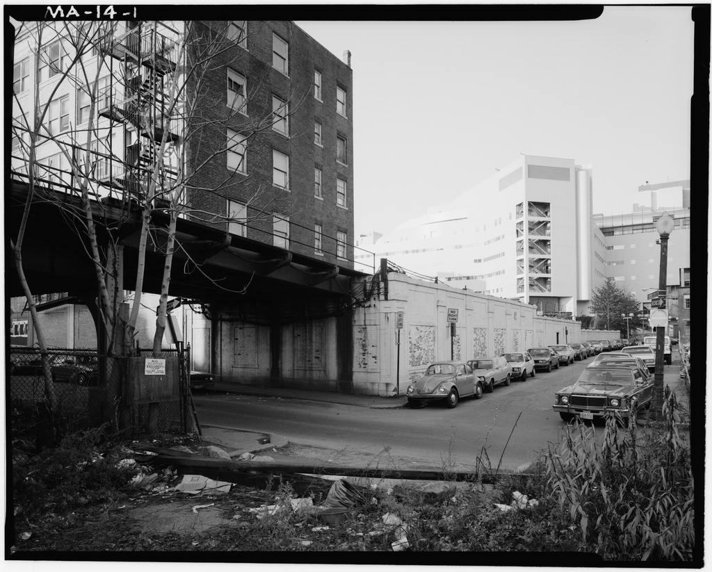
Guild Street to the Arborway - Section Boston Elevated Railway Company HAER No. MA-14 Page 53 6. Arborway to the Forest Hills Station and to the storage yards. Sections and II. Description by Segments (1) SECTION F-l South Portal to Tower D (Bents The initial segment of the elevated system, after it emerges from the Washington Street Tunnel, and up to the point where it crosses the current location of the Massachusetts HO-32 Turnpike (formerly the B&A does not run colinearly with MA-14-2 a street on grade. It does, however, cross some minor streets. Since no street runs beneath the rail line, the designers chose to support the system with fully braced fra- mes, presumably for reasons of structural efficiency.
The bracing consists of running from the support girder at one column to the base of its paired column. Since the transverse girders are relieved of their moment resisting function, they are relatively shallow. In addition, the spans are short in this segment and the longitudinal members are framed with girders, (2) SECTION F-2 Tower D past the Cathedral (Bents Boston Elevated Railway Company HAER No. MA-14 Page 54 After crossing the turnpike the structure joins Washington HO-6 Street. This is the location of the original "Wye" con- MA-14-3 necting the Roxbury Division with the Atlantic Avenue loop MA-14-4 (Section D), Elements of the original framing remain along with the original switch tower and its supports.
MA-14-5 Supplementary cross girders span between the columns of bents and forming secondary "transverse" bents, presu- mably to support the old "Wye". Remaining track support gir- ders and trusses run perpendicular to the later alignment at this point, Approaching Dover Street solid girder bents were employed. MA-14-7 At the station the longitudinal trusses diverge although the MA-14-12 tracks now run in a straight line. This appears to be a vestige of the station before its rebuilding in Upset MA-14-10 girders were employed for track support at the station pro- viding headroom for the ticketing lobby below the station. These are interesting in that no secondary framing was used, but instead oversized ties span between the bottom flanges of the girders to carry the rail loads.
Platforms are carried MA-14-12 by additional longitudinal girders. At the station, the standard girder bents are fitted with cantilevered outriggers, supporting the platform structure. Boston Elevated Railway Company HAER No. MA-14 Page 55 MA-14-13 Proceeding south from the station, Washington Street starts out quite narrow, and the bents span from sidewalk to MA-14-14 sidewalk. Shortly, the street widens a bit, and short spans replace the larger ones with columns coming down into the street. Some solid web and some trussed girders are used. As Washington Street veers to the West, a substantial offset occurs between the road alignment and the rail alignment MA-14-15 giving rise to very asymmetrical loading conditions.
These MA-14-16 MA-14-17 are marked by a series of special transverse bents some with cantilevers and some with a hybrid truss - plate girder form of construction. (3) SECTION F-3 The Cathedral to Thorndike Street (Bents As Washington Street passes the Cathedral it starts to widen. MA-14-18 The rail line supports become variants of the type "F" arch- truss bent. The road and track alignments still differ, inducing asymmetry in the supporting structure. Columns are frequently centered under one track, and a shallow trussed girder is used in place of the full arch design. Cantilevers are employed as necessary to resolve the alignment differences. Beyond the Cathedral, Washington Street becomes wider and regular.
The standard elegant type "F" arch-truss bent sup- Boston Elevated Railway Company HAER No. MA-14 Page 56 ports the system here. Since columns are directly under the track loads, the bents could be designed as light, efficient forms although subsequent analysis has revealed deficiencies in the lateral force resistance of the design. (See MA-14-20 Anderson-Nichols & Co. report). [4] Washington Street is quite level in this area, so that bents have a fairly constant height. Longitudinal members are trussed adding to the light "airy" appearance of this portion of the line. Engineering News observed, "The structure ...
leaves the street much more open and unobstructed than does the usual elevated railway, and the cross struts being arched present a handsome appearance as well." [5] At Northampton Station, columns move to the ends of the MA-14-24 bents, apparently to allow more horizontal clear space below the tracks for surface vehicles. An additional pair of longitudinal trusses supports the platform areas between the tracks. In place of an arch, the transverse bents have a constant depth with trusses used under the platform areas and solid web girders under the station house. (4) SECTION F-4 Thorndike Street to Guild Street (Bent - Guild Street) Beyond the station, Washington Street continues regularly till it starts to aproach Dudley Street and the type "F" Boston Elevated Railway Company HAER No.
MA-14 Page 57 MA-14-26 bents continue through After this, the tracks converge and the street narrows and winds to the west. Girder type transverse bents with a three-hole style knee brace span MA-14-42 the street to carry the longitudinal support members which continue as trusses. MA-14-28 Dudley Station was the original terminus of the system. The line terminated in a loop of fairly tight radius, necessi- tating considerable additional lateral bracing and support. Around the tight curve, non-prismatic transverse girders were employed to create the necessary banking.
Even so, this curve was the scene of a major derailment in shown in photographs and In addition, platform and station supports, as well as support for the elevated surface line loops complicate the appearance of the structure here. In the areas of the station where "a minimum elevation of the tracks was desired, with the standard head-room below for street cars and where it was necessary to prevent drippings, a special through girder and solid floor construction was employed." [6] Supporting structure for three tracks wye off from the loop MA-14-44 and continue south along Washington Street, forming part of MA-14-45 the former Guild Street Yard. The end of the yard segment marks the end of the old style trussed longitudinal girders, Boston Elevated Railway Company HAER No.
MA-14 Page 58 and the end of the knee braces with three holes. Two of the three yard tracks form the connecting link to the line exten- MA-14-46 sion south of Dudley Station. (5) SECTION F-5 Guild Street to the Arborway Proceeding southward from Dudley Station, Washington Street becomes narrower and passes through a much hillier area. The portion of the rail line which follows this section presents a more utilitarian aspect than did the original portion north of Dudley Station. In addition to solid web plate girder transverse bents, longitudinal members are now structured as solid web members. Knee braces have been redesigned with a single hole, giving the whole structure a heavier appearance.
In certain areas, Washington Street dips markedly, and extra high bents were designed to maintain the rail grade. These Bents, through and through have an additional line of secondary bracing comprising a laced MA-14-53 member spanning between the columns. "X" bracing runs bet- ween the transverse girder and the horizontal brace. MA-14-47 Conversely, when Washington Street passes over a hill, very short bents are used, such as number Where cross streets occur at an area of short bents, longitudinal girders have been redesigned with lower chords which arch upward to Boston Elevated Railway Company HAER No. MA-14 Page 59 gain clearance. The arch is usually composed of curved MA-14-62 segments at the span ends, while the center of the span is still ususally straight.
Occasionally the bottom chord is formed as a single long curve. MA-14-50 Track and street do not always align in this section, but the misalignment is not so great as in the northern portion. Individual girders are adjusted to accomodate the varying load position, usually by varying the size and location of flange cover plates and web stiffeners, but occasionally by means of cantilevered outriggers. Standard track support framing is employed at Egleston Station, with the exception of one span where upset girders, with floor beams and stringers, were used to gain headroom over the passenger access ways. This section of Washington Street from Egleston Station to Green Street Station becomes very regular, and the track sup- MA-14-63 port structure is also very regular.
Typical bays occur throughout the section, modified only by the occasional arch- chord longitudinal girders as described above. Green Street station was added to the system in after the main design was complete. As a result, the principal MA-14-64 track support structure is unchanged through the station. Boston Elevated Railway Company HAER No. MA-14 Page 60 MA-14-66 The ticketing area is hung as a gallery under the main longi- MA-14-68 tudinal structure. (6) Green Street to Forest Hill Terminal Proceeding South from Green Street, the typical framing con- tinues until the Arborway is approached. This is the final terminal on the system and its design varies greatly from the rest of the line.
The support structure is steel encased in concrete, with single pylon-like columns carrying both longi- tudinal supports by means of a "Tee" shaped double can- tilevered head. Each pylon actually contains a cluster of four steel columns, laced transversely. The longitudinal support is encased in concrete with a long arched soffit spanning the center line between the columns, Within the station, two-span transverse bents support longi- tudinal girders. The exterior columns of these bents are encased in the concrete outer structure of the station. The longitudinal structure comprises both conventional deck-type girders and upset through-type girders. The major design MA-14-78 features of the station are more architecturally noteworthy rather than structurally exceptional.
South of the Forest Hills terminal, regular plate girder MA-14-82 transverse bents carry the tracks along Washington Street a Boston Elevated Railway Company HAER No. MA-14 Page 61 short distance, and begin a gentle grade to the existing storage yards at the end of the system. III. Subsequent Analysis Between and the consulting firm of Anderson- Nichols and Company, Inc. prepared an analysis of the state of the Orange Line at that time. Their report [4] gives a detailed description of the corrosion and disrepair the ele- vated structure had fallen into, after 30 or more years without repainting. While that discussion is not directly relevant to this description, their analysis contains some interesting information.
The original structure was very conservatively designed, with a maximum design stress of 16 kips per square inch, and most areas they investigated deve- loped stresses around 10 to 12 kips per square inch. This overdesign was responsible for the continued serviceability of the structure, even though corrosion amounting to as much as 30% loss of original metal had occurred. Design inadequacies highlighted by sophisticated computerized analyses were ^ery few and were mentioned above. Their conclusions were that, corrosion notwithstanding, "the struc- ture was found to presently be in an operable condition." A program of repairs and painting was proposed and carried out which extended the useful life of the system into the Boston Elevated Railway Company HAER No.
MA-14 Page 62 NOTES Chapter 6 [1] Engineering News, Vol. XLI, No. 19, May 11, [2] Engineering News, Vol. XLIII, No. 11, March 15, [3] Engineering News, Vol. XLI, No. 19, May 11, [4] Structural Investigation and Analysis, Elevated Structure and Stations, MBTA Orange Line. February Consultants: Anderson-Nichols and Company, Inc. [5] Engineering News, Vol. XLIII, No. 11, March 15, [6] Engineering News, Vol. XLI, No. 19, May 11, mm Boston Elevated Railway Company HAER No. MA-14 Page 63
Bibliography
Blodgett, Geoffrey. The Gentle Reformers: Massachusetts Democrats in Cleveland Era. Cambridge, Massachusetts: Harvard University Press, Boston: City Planning Board. A Compendium of Reports and Studies Relating to the Commerce and Industries of Boston. Boston: Boston Printing Department Boston Elevated Railway Company. Fifty Years of Unified Transportation in Metropolitan Boston. Boston, Reference List of Literature on Electric Railway Transportation in Boston as of February, Boston: Boston Elevated Railway Library, I927T Statutes, Surface Railway Leases, Contracts, etc., Boston, Urban and Electric Railways: A Selected Reference List of General Literature.
Boston: Boston Elevated Railway Library, Boston Local Transit Companies, Annual reports, financial and other documents of the Boston Elevated Railway Company, the West End Street Railway Company and Boston horse railways. Corporate Records Division of Baker Library at Harvard Business School. Scrapbooks and miscellaneous data. Massachusetts Bay Transit Authority Library. Boston Street Railway Association: The Boston Transit Album Bulletins No. Fourteen and No. Seventeen - Bradley Clarke. Boston Transit Commission. Annual Reports, Cheape, Charles W. Moving the Masses. Cambridge, Mass: Harvard University Press, Cudahy, Brian J. Change at Park Street Under: The Story of Boston's Subways. Brattleboro, Vermont: S.
Greene Press, Geretsegger, Heinz and Max Peintner, Otto Wagner, (New York: Rizzoli, McKay, John P. Tramways and Trolleys: The Rise of Urban Mass Transit in Europe Princeton, New Jersey: Princeton University Press, Mason, Alpheus T. Brandeis: A Free Man's Life. New York: Viking Press, - - .. jfWea. Boston Elevated Railway Company HAER No. MA-14 Page 64 Mason, Edward S. The Street Railway in Massachusetts: The Rise and Decline of an Industry. Cambridge, Massachusetts: Harvard University Press, Massachusetts. Board of Railroad Commissioners. Annual Reports, Massachusetts General Court: Committees. Boston Elevated Railways, Reference List of Literature Pertaining to the Transportation System of Metropolitan Boston, Boston, Rapid Transit Commission.
Report of the Rapid Transit Commission to the Massachusetts legislature, April 5, Charles E. Powers' collection of clippings in the Massachusetts Statehouse Library about elevated railroads in Boston and New York. 3 vols. Meigs, Joe Vincent. The Meigs Elevated Railway System. Boston, Middleton, William D. The Time of the Trolley. Milwaukee, Wisconsin: Kalmbach Publishing Company, Miller, John A. Fares, Please! New York: Dover Publications, Peabody, Robert Swain, Holiday Study of Cities and Ports (Boston: Boston Society of Architects, Pinanski, Abraham Edward. The Street Railway System of Metropolitan Boston New York: McGraw Publishing Company, Reed, Robert C. The New York Elevated. New York: A.S. Barnes and Company, Reeves, William F.
The First Elevated Railroads in Manhattan and the Bronx, the City of New York. New York: New York Historical Society, Sprague, Frank J. "The Electric Railway," Century Magazine, 70 (July-August Street Railway Journal, Street Railway Review, Warehousepoint Trolley Museum. Transportation Bulletin No. 82 Jan. Bay State Street Railway. Warner, Sam B. Streetcar Suburbs: The Process of Growth in Boston. Cambridge, Massachusetts: Harvard University Press, The Urban Wilderness: A History of the American City. New York: Harper and Row, Boston Elevated Railway Company HAER No. MA-14 Page 65 / Whitehill, Walter M. Boston: A Topographical History.
Cambridge, Massachusetts: Harvard University Press, /J- Zaitzevsky, Cynthia, Frederick Law Olmsted and the Boston Park System /-- Cambridge, Massachusetts: Harvard Unversity Press, Zaitzevsky, Cynthia, Nikita Zaitzevsky and Calvin Gpitz, "Four Bridges on the Providence Division of the New Haven Railroad," HAER Report, Boston Elevated Railway Company HAER No. MA-14 Page 66 Notations Boston Elevated Railway Company HAER No. MA-14 Page 67 Notations Boston Elevated RaiIway Company HAER No. HA-14 Page 68
Appendix a
Chronological History of Orange Line up to Boston Elevated RalUay Company MAER No. MA-14 Page 69 3-2 - c e u 4J U JJ * o i v 1*1 c u *> Jrf u 3 US O i. & il ... ;s* a. is* > e o cv 5 lA * * WOE e w - Of >>o T3 If r > c k* .^ ^ i^ O o * A _. >, -Q L. i. ^ * o -v C J( a5 a - c? 4 J" IS <1 II o 1_ (_ 01 41 > * J *l c L. > -o T3 CD Z ** - i tJ 1" E I <u - - ( * . V C CM 9 f 4 1*1 * in S * "9 CO t- e o so I* Q. 3 O 3 i- CO _ to a, o wV- cw ,- u. _/ * -. ~i * c C U U v> S -. a o >i i_ ^ V o e i 4J U e ^ L. A f% * L. -0 .C 41 -* .*< a - 1 1. zs 1i 2u i* a _ j* > u. A 111 o m z w u C *J SJ i3 * - C 4 * "U CTI e $ I e I M X o L. <** < a. % * o A v 5t- (- V w Of ij. i. I. 11 " c*j r-> OD 1 * *(. ifl t"i ("1 CD w t. c l: il 8; II .its i. to IA VI>. C C o * M: m v. w SI'S 1 2* V> W ! W - Ul _ CT.
3 *J V 1- ^ ^fl t t 8= = = o D tj IJ c >c tiv tl >* 3 >i I o> c o >-l 3^ 9J *- lO -VlXAiCMk/lV ">> H (O VI c a- ai v> (M Vt (. }^ c u ,w * 2 as I* site by 5 " tolo celo i krt w CD !! a* X*1 ti sg! +* m m CO CD eeao s Boston Elevated Railway Company HA R No. MA-14 Page 70 VI +-* f ^J m 3i L. - "3 3 T3 > C S L. o t. vl UJ 4- 3 UU1- J= C u> 41 u i; u C 41 _ a tJ o *J . C 31 t. -a IO T- C 3 C C > c _ vi n L. 4-1 -f- a o &> u at w ^ -- 41 ~- 1/1 vi 2 C O I 4-1 3 "3 (= *- Cf O. 13 x e i- n ^ u ri *- - u u aco m o i) 'P a. *a 3 v> c T3 o .e 3 o o O Ott i- S 41 <J e (.m a 41 4-> e ^ > c t- u 4) O o o <a vi K 3 3 Ol VI i o t. "3 -o 4J L.
*> (rt n> , 35 4-> J3 "3 >> 3 ar c U 41 -C L 3 CTl a.- o u CO O i- -r- O.^ S> v> =o i -o y 41 41 4J i- 41 % 1 a OIL (3> 41 4-1 VI < .1* 41 3 ^ 3 t *J t- 3* ^ *J t 4-> C i/l C U O. O 5 U a; VI Ol *J V m (J t- 4-1 41 41 CTi 1- 31 CO 41 O L. 3 O 30 r- 41 J_ vl 4- <: a a. c ii t-uj 01 j_ J3 - u 41 c J U 3 3> V) T- C c 4J L. > T- 3 Q. t- <*- l/l 41 -o 41 It- C" . U /$ o > a. * c- +J ifl UI 4-1 i 41 u t- . C- C J3 41 41 U 3 IIWOTJ IV -3 .e -f- c - > +J i- X o .j* JJ E 1 = C U4 >, U S U V U w> -a % =1 3 c -^ i- _ a>i/> stea i! 4-> ^c V B CJ c 5 a O 44 - - u (/] VI B ut 4> ui O i ^ ^ S <~ oe 4-i VI c - O O JJ o * cue u * vl O Oil" o ceo w 41 s *' X8- v) 41 C 3 II Si O u i *J ^ ^ S </> tj e *-0 ^ . 4U X flj i- -S 41 4-t 4-> fl w > O u & +-1 at i; w w r# o ^ 41 ** . 3 o. ui ui O >.
( 4 a O *4 (J V <*- CO o 5' ui w c ui n) *-> 41 c a o at o X i/l u> _i *J tJ 1- wi V *v - e u * - -rs ti u 5? 34 >- 3( vt rO C i J= *J *>1 -a >, is >. 3 Ul C UJ k >^ < * 1*. vt T3 4J fl u O G X U c a - c * -* >. <- vl *- UJ UJ eo V V M t> VI u a * o *4 l v o a o -u 3 i ' < in - f ib CO *J S o c I* * A>* Ol tn 3* W> 30 X ui en * "3 U t7> w o 30 u >- 4 c ^a L. VI t- 0 L. t. UJ 4 r-< 41 Q H O >. 41 4f ^ 41 (NJ a. * tJ <- X 3 ^ SJ o 1 o u S K oe o C *J x; u > o hi ea 5 w 4 *; *J u X 41 *_ <J 3 c <* 3 " ae l/t **< a. < - -> o o-o L. e CV LU u Vj C . U jj 41 41 a o o O soa uu *T 4 V Z < u so en o 00 cj Boston Ei evated Ral Way Company HAER No. MA-14 Pago 71 a* > t- -t- <y i~ c C L.
a a -^ _o as o LI o c i- > Tl UJ O v> sm (/> +J Sn C 4-> 3 a> > it 5 a f ' 4J <7l r <3N 3 OO -_ - <_ > <7i JJ 4- CO E fc3 <J Ol VOW O >i <- C 4-> 5 -w Q, W 41 g JE X O l 3 W jQ On 01 i= ItlH X > - fl) wl Ul 4J O -P- *J *1 C * - e Q. VI *- 5 S s IA *-> go B M ..So 9ui wo wi a u o 4*5 (A 1- (. *J < 4im -o CO < > <-> O <- < V - 4>> Mi (It 4-1 H a> P4 w c co U 4J V. 4 - J 3 fc. 30C * O s ziU L. 3H ^> 41 e L. <j 4 O 4J B O V ft- * eo v (. W ul 41 V 41 4-> V 3 > v e 3 o 41 l. c Vt ** 8 8-fca 3S 3 3s* 41 * </i u a > ist 41 i_ c *> o e t~ c o a. o JJ * en o m c as m & 4-t 31 4J t 4* 4-t 9 ai JS c a -" 4 C 4- * >,o 4> *> *(- i M 3 -a * a * 4; t o a OCUJ e C W 4- 3 r u. < <V C - - C 3 8 Boston Elevated Railway Comoany HAER No. MA-14 Page 72 <Q i- C C V * a. 1 .e o <- i- L.
*J -a at 61 a.-a ^ >, i a X 01 41 C Irt W 4> - 4J {_ {_ > C e no< o ^ -i x: i- 41 m <v i J= ** HI 01 T, c qj "i *- *- 4> Q Z a i- v in *J 4-1 JU. a ss l; I O t t x n : . & < aco 41 T3 3 U O O i o *J T3 +J o v - uu ' 41 4 ^ I *J > t- O V) n) I ") O . t- O i. O E <-> H^ o 3 41 U *j i _ o C 3 k> * o ^ r rt> c e ai < - (_ t. 31 4)1 4> d. O i- c o w *: j-i -r. C *- *J JJ oi nj at ^ s- C in T- 41 K- - o 1. a. i3 XI - 3! u a s (-3 (* UK lav >43u isp, o c n > ifl ai *J C c3 v a. 3 3 JJ 3 ai b * 41 J 4-1 3- CO w is < <M n be t Gu a a. ** *- 3 rfO C i. (_ V) prt o -w ,-* * *J ;n w C 1 >* u o <0 s- . t/t X -*. a a<* (. *. L. V< 3 fc C 01 u O U *- +J tJ O ! ^ ri* r-- W 4> 4i <~ 4i > c ** u Olc 41 (. <nf o a u <_ 3 | kj 4i X <u i/i L3 o.a s s Boston Elevated Railway Company HAER No.
MA-14 tfl - a Page 73 -a Oic tn -fl 4) 2S c TI a. - - t, O 4t X rg 41 i-U i- -a l/t flj in > - W 3 c 5 41 O 2 o W -~ - 2 41 C - C ifl O U >, ^ Ol 3 X 0) *J U Vt in u c '** a trt 3 ig ^ O 5 a O >- C VI A *J 4J 41 w J 1 o u- > i_ - <*- a *J -i- 3 C 3 o u **w i XL CL OWI. vi 41 oS . o T- JJ 41 l_ +* W 3 1_ *J c Ml a e c -o W +J c i v <q f o e *>u * 41 < c * s U V) c 3 v *J 41 *J in I- (- O C bk O > a o vt 3 o in y I* > 91 w M >- VI 4) *** V &- ?* " VI L. 41 *J *J >i uw > *J a .. u t_ ^ ^ *J .< * 1* vi O W J UJ . V) l- c a Pri fl * (4* ^* 3: * >^ ^ (SI f >> u c L. , * V c* (Tl t_ a* l <n * *J > c -* > o a t- i l M 1- VI <- . fll t_ * M +J 41 ^ 41 13 3 "O <r i <x> L. J O a* s? ^^ a> o 41 41 <- iii e g k o 1/1 c OS e o w 4 v h. a ^ o nj -I t- - Csl O (. t. w o -o w >vc V. Ml .
p A ** *- L OI3 u >u s* ti U W 4 1^4 >(. u U *J 3 ro t. (M O *J W 3 C (_ UOfl *J < '3 8 *J .c VI ,^ ^- * e vi .. Vt *J VI 1 ^- u >s *J e 4J X => 3 i. a S lO tJ VI Q 3 a> 3 in - e m u b. s w C "^ Uo wt~ -. * O C C CM i- e u. LU o BC C o C fl 9> 1) "3 JJ _J a 13 3 3co "3 A. ** z -9 ai a. K O Boston Elevated Railway Company HAER No. MA-14 Page 74 APPENDIX B Copy of Contemporary Description of Electrical Systems by Frank J. Sprague, as Published in
The Electrical Review
Dec. 13, through Dec. 27, Boston Elevated Railway Company HAER No. MA-14 Page 75 U49 NO 1 ,i| DECEJ,RF 13 1W1 tVoL . Ko. DW WTH - - '-' " - 1 THE ELECTRICAL REVIEW. 9o9 * P<JPU WlOlLOf OT8T Mid . SPRAQUS MULTIPLE UNIT SYSTEM. to y itreM on the proriiion limited u*er of th W id*j ut B that the wtMw^yE A3 APPLIED OS THK BOSTOX ELEVATED RAILWAY. i Administration of .the w Br J. SPBAQUE.
the dTi* l,iU[j of oropoeing ^ roo.ce lo be held neit ,^r i Wu*- TBE mnitiple unit system, reduce-1 to commercial practice in Chicago only four years ajro by tbe nriter, is notr recognised >.tit eMMid dawi the timeoLj jtthe preferable method of operating electric railways on all c o( the TocbnUry h .ppeE?*" coups'** service where there are frequent trains of variable jogtOi an<* [be need is felt of *)tiick and economic hand- joeof anita at high schedule speeds. It has received the ^hest pra<tical endoreement, the adoption already of over OPEN AHD CLOSID. .j<i,n00 of equipment, and it is reasonably safe to eay ;iatfor the class of service for which it is designed, no OPXK.
other method of train operation can approach it for effec- ;mber Tenders are invitai U y of the Coloniea for the lopply tf ^ ijrenesB. The system is really a method of train operation and Tbe municipal anthoritia control) by means of which cars are equipped with motors don until the March lit, (MI -jid motor-controllers, individual to these cam, so that they PlO. 1. or BOSTOH ELBVUKO RAILT.IV. - lighting installation. Tender! in tee; to La College, EcheriDal, Ghent, ift ifoed Groin Lc Borean dee Trans*, Corporation Tramways Cotnoiid of the following (tore* for the 11 awfct 12: Poplar wood block*; cut-ifmteha *; motor gre**e ; rir r Mud; 'tun J bnubet. ith.
Electric lighting at Sos ofg torn the Miaittcr of Public Worb, Cia, Estimates will be opamU t, France, oo prox, for th* tqiplr pomp*, for iha porpoM of raiaioc writ ge tutien,- ud at the Hotel d Tift, e date, rapplr of two electric gioopi Information in each CMO tnm Tenders are being inrM French Port tod Telegraph *ntberiti*i i kilometres of iron pipe* for poetM* * tent to Le 8oue Secretariat dtW * Hue da QreneUe, Paris, Pipework and mechuiol setridty works for UM U.D.C. * * Helen and rat- fit. 8e "OfflcUl Notice." Donate Piping, pomp*, feed bestir, kt "Official Noticea" to-day. -ion Electrical Engineer J; o .idTtniK for tenders for (1) enoU* lO-a.f. wfttertol* boiler; (3) r plant; ud {*; one djuoo aea t* ibuard. -iili. BoUen and eontoouw. ipet, djauso and feeder peseta mb.
Electric fire ilann >l, Hanptfcad, for tbe MttropolU" fto- 3.-Tro-CAa il Notice* " November >cr \?,ilu Steam piping, iru* *T uterr, iwitcbboard, arc lamp*, ( " [htiog wojkt. Sew " OffldaJ *4rta STATION *r Stoneware cendniu f 4, 4c, (or CoottJtiin esfuem Electric light fitting a* iildingi foe the Corporation. Set r Tenders are invited for 1 and 3 of lobway fur electric Mbta .let- a ad yneeo Btrect, Bra4lord. **? be united *ith any namber of other can similarly a train of any length, um! <>| eroted from aa miiny roint$ o< i <f paf* gripped, or with my number whiuli hare no uoton, into desired through a controtlios line common to all cim The F Boston Elevated Railway Company HAER No. MA-14 Page 76 THE ELECTRICAL REVIEW r_v..i. n. x.. i.r..-.. n. T n. 41. N-.
i DI-.-I- number of cars, their sequence, and their end-to-end sible. In the history of transportation no more difficult relation, are matters of indifference, and the character of curvature from a comm problem has been undertaken than the inaasuration of ihe Id circles. Many of the find capacity of tie equipment are dependent upon the elevated service on the lines -.f the Boston Elevatedflaikav The ascendin? grades are schedule specified, varying from every car. where the highest The transportation problem in fioston is met complex. i\:,. schedule is required, down to tivo cars in a train. per mile ; the descending nils, or x percent, . j Et is endent that such a system lends itself to every con- Of die present railwnVt dition of congested passenger service.
The similarity of equipment ensures flexibility of train operation, and provides .i motive power [proportioned to the requirements. Loco- motive operations are abolished, trains can be reversed at any cro=s-ovcr, and traffic concentrated on any section of a mad. - The safe interval between trains is dependent upon the maximum speed and the power nf control, nnd hence both the time and the distance intervals between trains can !w reduced. With hi^h-power equipments any required schedule up to the maximum Incomes possible, and the number of cars in service can be made a minimum. Where a crowded system has main tracks with branches, units for the different branches can he combined on the main lino, and split up at iunction?. Fio r, .
round in the subway, an iractnre nt each end of the i Surface cars had been m n nr f the elevated tines since the :j mate the track connections PiO. 5. Mi-ri-n.CcisTROLLUfi, ENGINF.FII'S \SO AIR .i reconstruct the subway p QU-OK. IM necessary to discontinue t :se subway. With a vierc streets are narrow and crooked, and the inner terminus for --flience to the public us p> most of the travelling public is a restricted area and liring a week-end. On Sat extremely crowded. The congestion of the car service i< o'clock, the last surface car - considerably removed by the construction of the Subirat," i Monday morning, June tot built by the Rapid Transit Commissioners of Boston ad -rrice ivas begun. Over l leased to the street railway company.
This afforded lemporart :J time in making the chan; relief, bat it was early found to be inadequate for Boston- :t track, signals, platforms a growing needs. :'tfed in operation, the largest The necessity for improved service being seen, plans n "i re-arrange the operation of made and work actively prosecuted one result being the "jfeforthe changed condition. elevated system shown in the accompanying map WO surface cars are run on i (tig. 1) all of which, except the portions marked A . Daring the change- crossing the Charles River, and c n, to South Boston, ;> nrr ichedulcs and lines built and in operation, with about 1 " miles of track. Witbont ;^r ion.
This irouid not personal inspection of the road, the boldness of the eoncepdod sibte darins: the middle of tt * rtreel traffic would not f FM . 4. SPBAOCE FOLDIXG C.IB. *nt ooniber of cars to be on tf H* starting of the elevate The operation of the system is simple. Ever; unit being '-'olred the changing of -". self-contained, and every aggregation of such being simply ^fwe cars and the inaueurat an extension in the length of the unit without changing its ->arfer points. It also enfltt general character, operation becomes habit.
Like band and tirion of a new transfer like train movement* exist whatever the combination of -airing the instruction of no J units.* Protected by automatic devices, a man of ordinary conductors of the surface I intelligence can handle trains with tc trouble, so far * 8-"i0,0oO daily passengers, AS the electrical apparatus is concerned, and with le instruc- '* nt were diverted frc tion than is required for the air brake. The highest safety ^wonted rentes of travel, being essential, the system of operation obviously provides it. ' tog day it is estimated hi cafe of failure of brake*, the machines throughout the nwd am carried .:0'i,"O0 p entire train can be safely reversed.
The current input to transferred at t he Sotiin the machines ia automatically limited on each one to its safe capacity. In caw of accident to an operator, the entire *t i this service was tindert power is instantly removed from the train, and if the master * "f the trainmen bail ev-r switch on the leading car is inoperative the train can bo ^*e trip over the road, : oprrjtcd from cither end of any other. In fogs and on Pia. 7. Prr.oT MOTOR nn-..mo r mi MIIN i'.'M,*<";.'Fl- ' ever had any experience f slippery rail*, a li.xcd schedule can l>c maintained moic "* eqoipment was entirely r.' effectively because of the tower maximum peed, and the cm hardly be appreciated. On r\ trifle orer 10 milO' ' osjority of the jKitron* h;id r losq distance travelled in linking.
track, the western route alone, there is an aggregate of i.*--' The multiple unit system ha* now bicorae n necessity, for of enrvatnre, and the longest stretch of stmisut track u * ** Mtraordinftry conditions an without it some of the modern, railway <rork would he impos- than '28 mile. If the track were laid out with this **- " triiftj rendered every possib! * fiery improvement conducive Boston Elevated Railway Company HAER No. MA-14 Page 77 -^ i,v 1, nFTi i3, i9oi.] THE ELECTBICAL EEVIE'W. 971 mvt 40 !* ->. Di:cEiinrn 13, xooi. y curvature from a common centre, it would complete nearly The guard rails are of 100 aection, and are rigidly lie hiiEorT of transportation no more difficult :., circles. Many of the curves are as low as 90 ft. radius.
[.sen undertaken than the inauguration of the fastened. They are'placed somewhat higher than the track |be ascending grades are as high as 5 per cent., or 264 ft. rail, so that the possibility of derailment is practically ice on the lines of the Boston Elevated Railwnv. ^r mile : tDe descending grades as much as 422 ft. per eliminated. The strength and rigidity of the structure is nation problem in Boston is most complex. TV -:!e. or 8 per cent. (tig. 2). exceptional (fig, and the excellence of the details of nf the present railway tracks, about mllea arc nnder- track alignment and special work is notable. The move- ment of trains is governed completely by interlocking stations and by automatic block signals of the electro-pneumatic type.
One of the track rails is insulated from the other, so that a track circuit signal system can be used. The cars are ali provided with automatic trip-, so that if a train is run past a stop signal, the air on the train is immediately thrown into "emergency." The rjnestion of control and equipment of the trains was one which called for the most exacting consideration. It wn* early appreciated that more than the usual motive power should be used. Equip- ment on more than one car in tlie train ;md the " multiple unit" system were considered imperative. In order to determine the safest and best system for their use, it was decided to invite the installation of three different equipments Fio. C.
MAIN CoxTBOi-LEn, OF.N FIB INSPECTION on test trains u> be run over the most difficult portion of the road the subway. The tests and investigations made were ,- and in the subway, and the lemainder on elevated the most complete and elaborate ever undertaken in com- . ncinre at each end of the road. petition for an electric railway equipment. The contract for the controlling system was finally awarded the Sprasue OPKNIK'. OF Ro.\r>. Electric Company, and this was followed by two additional ?orface cars had been run on the subway tracks nowoeenpied contracts, aggregating 150 motor cars, of whieh 100 are - the elevated lines since the subway was opened. In order already installed.
Bake the track connections to the elevated structure, and For the construction of the cars and the installation of all reconstruct the subway platforms for elevated trains, it apparatus on them most careful and exacting specifications -M -U! u.-iLtr.n. EsoisKvu'j VALVE, A SO Am j necessary to discontinue the surface cars on the tracks in were made. The cars are substantial and very solidly built; .-. subway. With a view to causing as little iccon- the seats are longitudinal, and centre doors are used. The J: M to the poblic as possible, this change was made platforms are longer than customary. The familiar " Sprague " narrow and crooked, and the inner terminus for -nag a week-end. On Saturday evening, June at folding cab (fig.
4) is ased for the mo tor man and operating the travellinj public is a restricted area and dock, the last surface car was run over these tracks, and apparatus. It permits the gates on each side of the platform erowfk-1. The congestion of the car service wa- Monday morning', June lOtb, at 5,30o'clock, the elevated to be of the same size, and gives free access across the plat- blv removed br ihe construction of the " Subway, ice was begun. Over men were boaied daring form. The cars seat 48 passengers : *0 more can comfort- 'be Ilapid Tran-it Commissioners of Boston and -time in making the change. In addition to perfecting ably stand up. Both motor and trailer trucks are solidly he*'reel niilwav company.
Thisafforded temporary irack, signals, platforms and equipment necessary to be built and of heavy construction. The motor axles are < [ in. i. it was early found to be inadequate for Boston' red in operation, the largest task in this limited time was diameter at centre with 7\ in. wheel-fits. The wheel base Mmnjie the operation of the surface lines, and to pro- of the motortruck is i> and the wheels AH in. in diameter. cesiitv for improved service being seen, plans were :- for the changed conditions of traffic, d work activelv prosecmed one result being ibe '."O surface cart are ran on the Boston sv iem shown in the accompanying mip During the change-over tem- -all of trbicli.
except the portions marked A B, "iry ichednles and tines were in ik- Charles Hirer, and r , to South Boston,,* - uioo. This would not have been I in operation, with about i:. miles of track, Without aWe daring the middle of the week, as inspucion of tlie road, the boldness of the concept** traffic would not permit the '.: number of cars to be on the streets. Toe starting of the elevated service 'ted the changing of .M lines of -~ e can and the inauguration of ^er points. J^tab called fir the "isjon of a new tmntfer system, -ring the instruction of no less than v coudoctora of the surface lines. Of '' o,0ii0 daily passenger*, fully ant. were diverted from their corned rontea of travel.
On their *-i>S day it is estimated tint Gfi * (d can carried people, and "'transferredat the RnthvanSrjnnre T b n this service vras undertaken not '' the trainmen had ever made a Fio. B. Mils OF^N' F n Is Mt trip over the road, and few *w had any experience with train service. The The wheel base of the trailer track is 5 ft. and the wheel- M . in D rn'iM if '* * equipment wan entirely new, and last, bat not least, HO in. in diameter. The wheels arc steel-tired, ami tiie wjorityof the i itron had never ridden on an elevated gear* solid and pressed on the axle*. Automatic reiipirrsof be appreciated. a over l'MO'*. extm heavy construction arc used. Kacli car is e-iiiir-K'! the western route alone, there isan agpw < > trafirdinary conditions sarronnding the operation of witli two I'lO-H.!'.
moiors, with side bar suspension. They amre, and longest nreld, of S^* " [r*ins rendered f\ ery poaoiblc <wtfogtiard imperative, so are riglita and loftn, BO thai the commutator? are on the same * mile If .he track were laid out with thii an**" - "ery improvement conducive to safety hu been adopted. side to permit of ready inspection. Boston Elevated Railway Company HAER No. MA-14 Page 78 072 THE ELECTRICAL REVIEW. iv-i. . s . i.i.v,, M l3. w. V.I. *'X >.' . I.2.-.S. Dy TJie (lir-brake nvatem is that of the Christcnsen Engineer- RKVKRSER. irter thorough in estigal ioa .( th in Company, The motor-driven compressor has a capacity The reverser (fiir. 8) ia of the same " ironclad" type u .MUM. the (Jrcat Northern 4 Citr iiail* of 20 cubic ft. per minute to a preS9ure of 00 The the controller.
The contact plates, fingers, and finger basr; rjcinip their trains with tt.e mailer cor engineer's valves have excess pressure adjustment {fift. 5). deflectors, bearines, and blow-out coils are mtetchanseab - 7;..-[iiion-Houston C&nipany. Limited. * -, :J meet tl>e above requirement-. The rovcrnora are of :he equalising type, and control all ivicb those of the controller, [n addition to [he mot*-, Tbe trains "ill eacli .icivh it,out 20" tt of the crimprcswira in ^ train. The cara are heated and reversing contacts, the reverser has a mulHed double ' -. tid will coaiist < ! se^cn coaches :n ail, , lijrtuod electrically. break" isolated by vuicabeston partitions from both v- iad two end una- will e.ich beicijuipped The multiple-unit control equipment is of the Sprspue type.
motor and the limit contacts. The reverser coils are ir.-.c- The working apparatus is located in a compartment under a wit-h a liberal margin above service requirements, and a: portion of the seat at one side of the car. This compartment effective between :;0O and <i<)0 volts. The plungers are is open through the bottom of the car. Complete isolation central, and jruided by phosphor-bronze mda. The rererser . of workuie currents from the inside of cars ia therefore brought to "open" by a powerful eccentric spring conoeciio: secured, srith. all the advantages of ready and efficient in- and the link connection to reverser cylinder is oonsirne:,..] spection which auch location ensures. The protection and that the reverser is "dead beat" when open. Pension is my.
isolation of the car wiring is a matter to which especial for the release of the cylinder from the driving median:-: attention has been eiv< n. It ivaa realised that the current for the purpose of ready inspection. value of any short circuit would be in excess of any reached {To h ronlinved.) in any service existing elsewhere, and that such short circuit might be hazardous. The current is collected from four contact shoes carried on lonz wooden shoe beams on the tracks, and the main car wiring is led to each shoe through a detachable shoe fuse. The shoe fuse clears any accidental THE ELECTRIC TRAIN CONTROL SYSTEM " " either on the car or by a contact shoe. From the ON
The Great Northern and City Railway
Tid motors, each o( a-l^.-h ), s a rat.-*i <- . junction of the contact shoe leads the main wiring extends ;e British Tboiii-OD-Hou'roti Ct moany . < to a protected compartment in the hood at one end of the :t litest improvements, including ii.e.-aj car, where the taps are made forliehts, heat, air and control ELECT&IC traction u now being applied on ill the new rulwiTi.. -c [he most perfect TtnitJalivo. t! r w apparatus, to the main switch, then back to an enclosed London, tad Menu destined at no diitaut date to snpcnedcu: M the >%m aa those which have been , steam loco mot ire on all City and labutbau lines. One of the Iit.s Unud flailwar, o[ w Vork, alter t-.
main fuse of the " Xoark" type, located under the car; linn to adopt electricity a* a mot its power from the oattet ii i;- isdtil!au*tii-e trial* of their capabiiiti^i ' then to the control apparatus and motors. Great Northern aad City Railway, which will rnu from Fio.i;- "JiijitemarB now in Mtiiftctorjoperaiio j, All of the truck, car and motor wiring is of special high- grade :t,OQ0-vo!t insulation. It is removed from all vibra- numajter control jj^teia coaaiitj in *c- i etmbcT of electrieallj operated iic- tion as far aa possible, and enclosed for mechanical protection. ;aWttitio? the series-paralle!
motor cent The controller equipment for each car ia made up of five ,-irent com bi oat ions of tbe motors and r component parts; a ma to circuit-breaking reverser for deter- xt in circuit with item, and a *epira mining direction of movement; a main controller for determining speed by variation of resistance and grouping of motors; two master switches connected to switch lines for determining the movement of the main controller and reverser; a secondary controlling train line terminating ia couplers at each end of the car ; and a reversible jumper for connecting tip the train lines on the several cars. In addition there is a set of relays and the throttle. These several parts areshown in the accompanying figures. MA[>- CONTROLLER. The main controller (fig, fi) ii of an " ironclad" type.
All cables are led to bolted terminals insulated on ?late, and connections are made outside the controller. The main contact segment! on the cylinder are provided with removable 1 j-in. copper tips, and each carries only the cur- rent of one motor. The contact fingers are screw ad jotted, and are provided with spring! of substantial design, rein- forced by a shunt of leaf copper. The finger bases are cast solid with the terminal atcls. The arc deflectors are of recon- structed granite, which combines in a moat efficient way high insulation and heat conduction. The control limit contacts and segments are isolated from the main contacts by a vnlcabeston partition.
AH exposed metal surfaces, other than contact surfaces, to the interior of the controller, are covered by imnUtuw, and are finished hard and smooth. The blow-out coil is of simple sod substantial construction, of liberal dimensions, and protected from working contacts. Means are provided for adequate ventilation of ennucu and coil. The insulations on the shaft are double-keyed, to prevent possible loosening, and are set onder pressure. >r>h^o ma,. s,o The pilot-motor (fig. 7), which drives this msin controller spindle, is rigidly bolted to the controller base, and is removable aa a whole, or the Belda can be removed separately. Flo. 5 CossttTiosa rott It drives the controller by a stepped movement through s Fio.. 1 Masrsa (.'osrreoLLBS/OPix. * cdTO- powerful spring and lockim pawl.
These are of the most ehVient design, to ensure " <|iiick make " of contacts, and to secure positive notching. The gears ran io ;vn oil chamber. Park to Moorfate Street, a diataaet) of tome 3\ nil*. *** " ^W mitch; e OBd, two m t tontioiier intermediate ttope. . ,. The armature support and shaft are forged from one piece of steel. The pilot-motor armatnre is so made as to secure To deal with the baaty pataogar Ua/Be botwwa t" -" (ab rb* on thti line, it i* *w*e*ry to hare a r P"> _. 3IT2r-iI!??l,-.,A*rt, waaee,rt < >e" rigidity of construction as well as protection of the windings. Mrriee of train*, aad a* stau?" ' < n are notm n or The commutator is of copper, insulated with mica, and the it ia cnentEal to employ a high riW of acceleration. . brashes are of carbon, with automatic feed.
All coil ter- Aeotbat requirement ot toe lint U that the train <** * ^i7BC6iOT0Bt artioo of the motor conlro of operation tnwitber direction tad lima *l w* * ?. ; ^ ao aent of the majut controller b, minals are of heavy copper, securely fastened, with means tieM and tpa re<ieir*d (or the rtontim of a low*"1 ^~ voooecftoD and motor eombmatioci for bolting the connecting wires. crowded U*mtm may b avoided. Boston Elevated Railway Company HAER No. MA-14 Page 79 v i. w. o.^m,ZDKWMR so, i9oi.] THE No.^6, ELECTRICAL REVIEW, 49. Ho. DcoamxB SO, SPRAGUE MULTIPLE UNIT SYSTEM. EELAVR, AUTOMATIC STOP, AND.THROTTLE. fes now being erected consist of The relays, automatic stop, and throttle 12) are- .d accumulator room. The boilers in As APPLIED ON THE BOSTON ELEVATED RAILWAY.
, and ace fitted with chain grate stokers mounted vertically upon a slate support, thoroughly insu- itere will also be added. Two Belliu lated, and the contacts are well separated and rigidly ker dynamos are being pnt down; each BT FRANK J- SPRAGUE. secured. The coils are held firmly in place, and the plungers ag 135 with a steam pressure of arc positively guided. I'lattnum or silver tips are used for ID is made [or the addition of a larger ery of accumulator* ii being (applied tbe throttle in order to require minimum attention and to (fionliiuini from page ensure perfect contact. The bridzing discs have universal aring a capacity of 350 ampere-hours :re . The system adopted is the thra- adjustment and spring cushion. The protective fuses for MASTER SWITCH.
ll a pressure of 240 volt* at the lamp*, the control circuits are carried by clips on the relay slau?. by Messrs. Kelvin & James While, oi Tbe master switch (fit:. 10) is of the cylinder type. Right which also carries for convenience the cut-out switch's and of the cables wilt be laid by Henri. sid left morement of a single detachable handle, normally [em, and it is hoped that the enpplj part of the adjusting resistances. iry. The wholo of the work ii boiog Electric Supply Company, under the engineer, Mr. W. E. Mi Ins. Mesoi. tors. iroe ago the Tramways Committee o the EX. Committee for a redaction of d to them for tramway purposes. Mr. r, drew up a report showing the charge! at week it was decided that the Corn- price o( 2d. per unit now charged.
Tbe nittee bad lost considerably la*t year on tt for electricity for the tnnu beLog ge charge only 2 rocetdi:ii;s of the District Council illivnai o|>er.is, or ot the story ot Bdeity, the KX. Committee elected i chairman, knowing that Mr. Shaw wu e latter then presided at a meeting of Fio. 12. t against the Council's electric light mmitteo pasted a resolution of want of goed, and afterwards tried to get the Flo. 10. lected, bnt without tncceaa. REXISTANI ES. men, electrical engineer to the The grid resistances (rig. 13) for the main motors are of had been called ID to report on the latched in a central position, produces ahead and reverse ist of lighting the docks, reported that motion, mid any desired variation of speed.
Movement n special cast material, and are of a loop form to ensure ling maintenance, WH 1 per unit, is opposed by a spring, which returns tbe handle to tbe flexibility. They are supported in longitudinal vmic.il e generation of electricity at the dock! planes on reconstructed granite insulators carried by angle -t.rici;il or " off " position when released, and automatically ration at Id. per nnit, provided it was irons for attachment to tbe car. Their construction permits of no its per annum. With main- cats off tbe main current.
The cover is lined with mice, reswd the opinion that per sail well lacquered, and is easily removable, Tbe vulcabeaton easy installation and repair, and secures reliable insulation onld be done for, and probably it would separators are hinged to facilitate inspection. The switch is as well as efficient radiation. ) offer the Harbour Trust the neoesssrT of suck form and dimensions gg Dot to restrict in any way They are of sufficient section to withstand the shocks of i a minimum qcarjtity of nniti service, and are of ample carrying capacity for the most tbe clear passageway across the car platform. extreme demands. All wire connections are made by means- tin? of the last week the torn TRAIN LINE COUPLER AXD JusirER. of bolted terminals.
.(the sanction of the Local Government iU.000 for electric lighting purposes. The train line is a compound cable, each wire heavily ' clerk of works, tor the erection of tbe insulated and tested at 4,OuO volts, and the; whole sheathed , it was decided to select three or more -iih a waterproof braid. The conplere (fig. 11) are iron the Committee, and after toe interview , was appointed at a salary of 3 3s. per 'hellsenclosing a block of insulating material, which supports he construction of tbe tramways ww die split-spring terminals of the train wires. They are con- e to confer with the electrical engineer nmed to tbe train line at junction boxes. The terminals arc report. if burr. The has appointed g engineer to the Council. .irporjiion has deferred consideration eme lor six months.
The baa decided to apply to tbe loan for eftabtiibing electric Ufttfa? ectric light receipts for the September d. After meeting the cost of prodocttM it and sinking fund, (iicre WM a fwpta irter. There arc now SO1 cost*rain IT of electricity aold was unit* Fio. 13. 3 TRACTION NOTSS. WeimiTs or EonriiENT* Fio. 11. b. delivered fay the Italian Premier, These arc tit fi llowa : last, be stated that aa soon as the Chamber without having reeoane to privai* cow separated by an insnUting partition, and are well insulated. Two Bjasur controller* 45 -Naples electric railway project before** Tbe couplers are shrouded, and are self-closing when not in project stipulates for the accompliihaMSi One set relays, foaee, switch;*, Ac 96 e two cities in 2 hours. ne.
The jumper, whose ends are contracted in a similar Ooe main ooarnller sad pilot motor 510 trial of the tau<b-sp ed electric rail"? dinner to the couplers, and have complementary female One r Terser 660 1 e wai made ud a speed of 90 kilometre Two Junction boxes 6 Waiacts, is reversible, and can be coupled in one plane only. Two coaplers, with attached cables sined. Tbe train was compoeed of t* 15 Both the jumper and the coupler are connected to tbe cables One juts pet 10 permanently at tbe back, the intervening spaces being filled Ooe set of grid resistance* 660 dvent of the trams in th insulating compound.
Each conductor is insulated OM set of maifir switcb and train cables 50 of waking up tbe local sbopkeepen on the oas are putting in new fronts and othsr- *ith ribber, ind protected with braid of various colour* to Total l.OTi ir popular patronage. facilitate connections. Boston Elevated Railway Company HAER No. MA-14 Page 80 TTJE L CTRICAL REVTE'W LVoi *H. NO. I,W,DWI I M.IDOL Vol. *9. No. DECtMBta SO. XHE Ol-KIMTION". resistance. In addition, the motors can be run temporarily 'iho automatic by opening the reverser eirctii In the Boston equipment tiie motor switch ia a separata with more or leas of the resistances in circuit for the purpose the controller to open circuit or any oili* piece of apparatus, operated when the rheostat switch is in of switching.
On heavy railroad work, such as on elevated position, reznrdless or the motorman. an open circuit position, hut for convenience of illustration and suburban roads, minor variation of running speed in The throttle is operated automatical!? by . either the series or multiple relation (if tbe one of the motors, and serves a double [uirpn* motors by the a* of resistances is rarely or stops the forward movement of the main : < practised, and is never necessary, save in desired current increment, and since it >' starting. The apparatus is especial!? mined value of tbe current, it can become an nut arranged to discourage any such variation for providing a definite rate of accelentir-n. of ran nine speed.
prevent any desired slower rate of ac^elerat:' The circuit which operates the pilot motor way remove from the motorman the positive "ft on each car is a purely local circuit, coraiaff main controller at will uithiu tlio limits of suf<* from the car shoes and returning to the current input. truck, just as the main circuit of the motor The coast series and parallel relays are oner1: does. It is not connected to the train tine form-switch circuits, which terminate in th^ n or the master switches in any way. Its path To this switch are brouxbt also the terminal is through the field magnets, brake and solenoids operating the reverser.
E\cept a- t armature of the pilot motor, through the is limited by the automatic features, or hinder' stances which he cannot, and is not intended t< =fe contacts of the coast, seriej, or multiple w relays, and nlso through the contacts of the throttle and automatic stop. If either tbe operation either of the particular car or the trai at the master switch. . _] ' throttle or the automatic La in an open (To be continued.) ' ciicuit position, it is impossible for the pilot Fro- 14. motor to move in one direction, and hence impossible for the controller to be advauced. and description it may be shown on the same cylinder as the although if in the advanced position it can be reversed. The THE CENTRAL EXCHANGE OP THE rheostat.
Tlie typical circuits are arranged as shown in circuits through the relay contacts and the pilot motor fig. 14, in which the various parts of a full equipment are also pass through limit switches on the controller cylinder. POST orrxci TELEPHONE indicated, as well as the inter-connection of circuits. If this control cylinder is in the "off" position, and tbe In ordinary operation the main motors are first thrown throttle and automatic stop are in the proper position, closing (Continued from ptuje .' into series with a resistance, which is cut ont until half the the coasting relay will not cause any movement what- "WE may now proceed to describe the connect! pressure is supplied to each motor, which is the half-speed ever, but closing the series relay will allow the.
pilot, if system of working. combination. ID, going thence to full speed, the main cir- otherwise uninterrupted, to move the controller to the sertu At the anbscribers' station there is a raa'j cuits are first opened instantly at the main controller or position, where it will automatically stop. In the same way receiver and induction coi!, a transmitter, ar verser, or, if desired, progressively through resistances and closiDg tiie multiple relay will move the controller either condenser. Tbe connections of these are shown u dependent main contacts. The motors are then thrown from the coast or series position to full parallel, where it ing diagram.
It will be seen that when the recei* into parallel, with a resistance in circuit hook, tbe receiver and transmitter arc cut 01 of about one-fjuarter that used in the and the subscriber's circuit is open to direct cor first series position, which is progressively lines are, however, bridged by the magneto-bi cut out until the motors bare fall pressure, ;ind run at their full capacity and speed. The ijuartering of the resistances on'tbe first position is effected by using independent resistances for each ao:or, throwing them in series and parallel relation the same,is tbe motors and using the same progreaaive >tepa. In any position of the controller the current can be cut off instantly by the reverser, which has also independent main- line contacts on the same spindle.
Provision \ miidc for dead-beat movement, and also for inter-conripction of controlling circuits by contacts on the same cylinder as tbe main Miitactj. The circuit for the rt reiser passes through the automatic stop coil, and ii ompleted through a by-pass on tbe con- troller in the first contact position, or through .i conmct made by the automatic, so that once opened it cannot be operated again unless tbe w n troller ii in a safe position for the motor?. The cylinder of the main controller is driven with an intermittent motion by a pilot motor through a powerful locked so that the armature of the pilot motor and the spindle of the cylinder do not move either in synchronism, or to an exactly like extent. This is necessary to ensure freedom from hot contacts and drag- ging of arcs.
The pilot motor h governed by live relay*, called, respectively, the "coast," "series," Bicsi \uw 01 Local. Bo.ao, CNDEK < o.v d -multiple" relays, the "automatic 9 p " and the " throttle." There are three ordinary sitions for a pair of raiiuay motors; the coast or open circuit portion, the running T CUIIAC TtttfMOKi BxcKisoi.-Vixw o* Kitu E*cx. with the condenser ; consequently the circuit is alternating current*, and thui the subscriber eai from the exchange. following the lines to tbe exchange, we series position, when the two motors are in series without wilt be aatofttsacall? stopped. Opening the throttle, ** coustant potential difference of 20 volts is_matt:t.i any resistance in circuit, and the parallel position, when the efer, will either arrest or retard the rotation 0/ the ibera.
by meant of a storage buttery. When tl. two motors are independently acrosa the line without any motor and the progression of the controller, and dropping takes hi* receiver from the hook, his spcatiritf Boston Elevated RaiIway Company HAER No. MA-14 Page 81 WRv [Yol *9. No. Dicncsn M, voi.*9. NO. I,3M,DBC* B *M.
Tbe Electrical Review
In addition, the motors can be ran temporarily the automatic by opening the reverser circuit will return closed by tbe switch-hook, allowing ,[a current to flow r less of the resistances in circuit for the purpose the controller to open circuit or any other determined through the transmitter and the primary of the induction On heavy railroad work, such as on elevated position, regardless of the motorman, coil ; the small shunt current through the receiver, the an roads, minor variation of running speed in Tbe throttle is operated automatically by the current in secondary coil, aud the magneto bell is negligible. either the series or multiple relation of tb one of the motors, aud serves a double purpose.
It retards AUbeexchange,thiscurrent passes to one of tbe lines through motors by the use of resistances is rarelr or stops the forward movement of the main controller at any the line relay, of GOu resistance -, this switches on the line practised, and is never necessary, save iii desired current increment, and since it responds to a deter- indicator calling lamp across ft preisnre'of H volts, causing starting. The apparatus is especially mined value of the current, it can become an automatic switch arranged to discourage any such variation for providing a definite rate of acceleration. It does not of running speed.
prevent any desired slower rate of acceleration, or in any Tbe circuit which operates the pilot motor way remove from the motorman the positive operation of the on each car is a purely local circuit, comiti" main controller at will within the limits of safe and desirable from the car shoes and returning to the t current input. track, just as the main circuit of the motor The coast series and parallel relays are energised by plat- does. It is not connected to the train line form-switch circuiU, which terminate in tbe master switch. or the master switches in any way. Its path To this switch are brought also the terminal wires of the is through the fit-Id magnets, brake and solenoids operating the reverser.
Except as the motorman armature of the pilot motor, through the is limited by the automatic features, or hindered by circum- contacts of the coast, seriei, or multiple stances which he cannot, and is not intended to control, all relays, and also through the contacts of the operation either of the particular car or tbe train is initiated throttle and automatic atop. If either the at tbe master switch. throttle or the automatic is in a"n open n (7V be conlinutd.) circuit position, it is impossible for the pilot motor to move in one direction, and hence impossible for the controller to be advanced, .:> the advanced position it can be reversed. The ugh the relay contacts and the pilot motor THE CENTBAL EXCHANGE OP THE LONDON mush limit switches on the controller cylinder.
POST OFFICE TELEPHONES. trol cylinder is in the "off" position, and the automatic st>ip are in the proper position, closing {Conlinutd from pagt L' relay will not cause any movement wbai- WE may now proceed to describe the connections sod the !o*ing the scries relay will allow the pilot, if system of working. iinterrupted, to move the controller to tbe seriis At the subscribers' station there is a magneto-bell, a -re it will automatically stop. In the same w ? receiver and induction coil, a transmitter, and a multiple relay will move the controller either condenser. The connections of these are shown in tbe adjoin- ar serk-s position to full parallel, where it ing diagram.
It will be seen that when the receiver is on the hook, the receiver and transmitter are cut out of circuit, and the subscriber's circuit is open to direct currents. Tbe lines are, however, bridged by the magneto-bell in aeries Duo a AM or
Connections between
StBscaiBEaa STATION AMD Eica.i^ct. it to light up, so us to attract the attention of (lit- operator. A lump of Gu w resistance is inserted in series with thr other line; its functions will be dealt with later. The indicator lamp is directly under the jack allotted to the subscriber who is calling. Hence, the |x.-rator 1MS no need to recognise a number us in the older i not hods, and to rind the corresponding j.ick mclies or feat away; in fact, she does not rwjuiie even to - tin; number of the calling subscriber.
Inserting nil answering plug into the jack indicted i here- npou the calling lamp goes out), and pressing ii.riv.tnl a switch ou the keyboard, the operator is at once in c niiuiuu- cition with the subscriber, ascertains the number wauled, and proceeds to make the dcsiied connection. For this purpose she takes up tbe calling i-lu- cirre- sponding with tbe answering plug just used, and ups the brass buib of the wanted subscriber1* jack, ivttii the tip of the plug. If she hears a click in her ri-cmer. An: know* that the subscriber's line is engaged, and inform* the Biti \uvi- or LoCiL BOAHD, OKDKB C'oxsnccriox. calling subscriber of the fact. If sik-uce reigns, bo-rewr. she pushes home the plug, and pulls over the switch pre- with the condenser -, conseqaentf?
the circuit is complete for viously used to ipeak to the caller. The first operation "iternating current*, and thai the tnbechber ctn be rung op caosea a lamp to glow, and the secoud rniis the ESUUNGI. VIEW or METES JUCK. front the exchange. of tbe subscriber wanted. hireetly he lifts !n- fallowing tbe lines to the exchange, we see that a receiver his "clearing lamp'' goes out. ac-iuainmi;r tin- tnaTTcaJly Hopped. Opening the throttle, ho * oii-tunt potential difference of 20 volu is maintained between operator with the fact that the subscribers .\n coHQet-ted. :her arrest or retard tbe rotation of tie pilu* 'hem by means of a storage battery.
When tbe subscriber *be then presses a buttoD, which registers one oil >>:i h> r the progression of the controller, and dropping tikis his receher from the book, hit speaking circuits are own meter and ou that of the caller. When thu n.i -tu- Boston Elevated Railway Company HAER No. MA-14 Page 82 No. DKUUI voi *a. Ho. uts7. D m i7, ion.] THE ELECTRICAL BETIEW. ttremcly low flat rate. Take xjDsumer, in his tenth hour SPRAGTJI MULTIPLE UNIT .Normally, Chen, movement of any master switch (the pay per unit by the others for the time beisg inoperative and held at open circuit) closes like relays on each car and starts the sequence although Mr. Wright's own As APPLIED ON THX BOSTON ELEVATED RAILWAY.
of operations indicated for a single car, but here also the uires As tbe produc- automatic variation of movement described in regard to a . and the total coat (including BT FRABK J, BPRAQUE. particular controller takes place independently at each car, 1 'iSd., he still pays a certain and different kinds aod degrees of movements of the con- charges. If, however, he it {Concluded from page trollsrs of dirlesent cars can take place simultaaeonaly if o latter, then at Id. per unit he TBE master switch baa (1) the off or normal position, Ui necessary. Not only that, but to provide for differenoe of f hich the handle is spring-retracted in case the operator lets wheel diameters, difference of tractive coefficients on different ery penny representiog d.
coats wheels, and to provide also against any irregular condition ps of it; (2) for ahead movement, three running positions, ppcna that one London supply coast, series and multiple or full speed, with no contact* on any car, similar movements may be differently timed, rate and 4d. after for the hoars between ; and (3) for the backward movement, two running and different controllers may take different relative positions d. per unit on & flat rate for the portions, coast and series or half-speed position. The car when measured by time, each accommodating itself to tbe urpose) during the hours of day- on be stopped and reversed by a single throw of the handle limited current input determined for itself. bt, the *d. rate will be halved.
of the master switch from one side of the open position to It therefore becomes possible by this combination of posi- the other. tive sod semi-automatic control to .combine cars having 1. initial, and 2d. follow-on, will Ordinarily, when a motorraan wishes to go ahead at half controllers of different sizes, motors of different capacities, id boura of darkness, and 2d. resistances of different gradations, gears of different ratios, speed he moves tbe matter snitch to the series position. The iring daylight hours, which itverser is instantly set for movement ahead, the series relay and wheels of different diameters, and to safely operate Wright's "ideal" tariff.
is closed, the pilot motor starts up, the driving spring is put them all from one or more controlling points, all of which, meters, one * for the " day" under tension, and the controller spindle moves forward of course, would be absolutely impossible to a band-method supply, with a- single intermittently until the pilot limit* atop it at the half of control, or anything approaching to it. with the latter, the consumer can speed position. II, during this operation, the throttle should SUPPLY. t i nd dear sapplies compare. It it lift, this advance of the controller cylinder will be retarded or stopped.
If the automatic stop should drop, the advance Current for the Boston Elevated service is delivered from ay change-over switch, with in the stations ss follows: not only will be stopped, but the controller will at once ran rated by band, may throw one or backward to an open circuit or other determined position into circuit; or if the meter* of rithoat regard to the set of the series relay, or the wish of ktkXtasw | Cm. arik. ' IW to aapacii}. , tl (t*Taw4 Vulcan type be is use, a clock the man at the master switch. AtBfam. f tadm. ttrosKm.
the shunt circuit of that meter Being at the series position, if the motorman wishes to go ;ster, the main coils of the two it foil speed, the handle of the master switch is moved to Cantial ' SCO In the latter case, however, the that position, when similar operations take place at the Saat Oamhrldge- relays and pilot motor ; or the operator may move his CaarleatvWB 4^M . d the top or greatest maximum M,0OO,000 200 witch handle at once from the open circuit to multiple, erely that of the load registered rithont regard to series, and the main controller, controlled 1 which most have occurred at a by the throttle, will advance to fall speed position.
Of Reference to this table will show the possibility of cur- coarse, the advance of the main controller may be made at rent flow which would follow a short circuit on the elevated till, step by step, by toach-and-go contact at the master lines. By reason of the grades and alignment of the system, (witch, and its advance can be art-sated instantly. If desir- and the high speed and frequent service maintained, the able, when a coast relay is used, its connection can bs fiofitaattons of load are severe. As the stations feed both and llieir Prevention. At a changed so as to, at will, throw the throttle out of action, elevated and surface lines, the flnctaations due to tbe . d Counties Institute of Enginter*, tithoogh this is not desirable. elevated service are taken care of without difficulty.
Derby, a paper by Mr. L. W.deGr e Comparison of the movements of the master switch and Observations so far made indicate that the current demand i Some Electric Accident*, and the the main controller illustrates very clearly the inter-connection for a section of the elevated line 1^ miles long, having in wu read. The author divided aeci- of controlling circuits sod their utility, and how they air operation nine trains, varies from 500 to amperes. k "" and " fire." Acddenta from fire intended to provide for every emergency whatever.
To all Even with such demands for current the minimnm voltage .its, and (6 bad contacts, la enlugifif ipparent, intents and purposes the controller seems possessed at the contact rail is 500 volts, because of the large section i, the writer Mated that it might be of an independent intelligence, because the relay system and of feeders sod the proximity of the power stations. The re, tir, or rope power, that a plant, the interconnection are such that all local emergencies are feeders used are of circ. mils, section, and are ran and maintained, wu perfectly "ie, provided for, as the; most be, without regard to the wishes, in conduit to the structure, where bare tin-copper cables He then deaJt with tbe technical intents, or carelessness of an operator. mounted on glass insulators are ued.
They are covered by uit ruction, and the proper provision of The description thus far u that of the operation of a a cable box, the top of which forms s convenient walk on naalatton of wirea wan anggeetad, and ingle car. To connect two or store cars together, aod to tbe structure. The several sections of the contact rail are r method of artificial reapiraiiM Uz provide for the initiation of tbe operation of the controllers on tied together by enclosed feeders of amperes capacity. iona. Mr. Deacon laid that h* loaaA workmen against electric accidents i> i sen other ears ss may be folly equipped from one or more Some of the elevated and surface line ssctioas are fed re* QDdeigrottad, in a poddltd-etoy 14 the matter switches, as well as to transmit control from two or more separate stations.
This ties the stations to llo traffic OTBT them withoe* | tkrongh can not equipped with motors, the independent train together, sad distributes heavy polls among the different observed that the Pan* police www : be is provided, which is the extension of the platiorm- stations. To farther assist in this distribution of " pulls," method of restoring elaotrowtsa j witch otreoit from car to car, through Hied train cables on the generators are given a drooping characteristic.
Thus, T;piied to the remark* that bad eh, terminating in conplert at the ends of the can, and when an extremely heavy pull occurs iu close proximity to ibie wu, in hi* opinion, the has* erxible and reversible train cables, or jumpers, terminating one station iu voltage falls, and the other stsxioss'tssist in many yean without having known a is coupler* with complementary contacts, and serving to carrying it- In addition, if any station by reason of .' enggettion of borying the wiiet ia i join the several train cables together at tbe ends of the can. leosUy heavy traffic is overloaded, a portion of its load is a very good one; be bad oaad it bin- fbese .train lines and jumpers are so connected to the shifted to other stations by voltage redaction at tbe gene- admirably.
India-iabbar glove* ba | ampling beads that the controlling circuits are antomsticaily rators by the field rheostats. The feeder system is carefully ,-en J they contained a pin-hole they paired to ensure proper operation of tbe varion main con- laid oat so that any section may be cot oat without inter- iuch to, in fact, ** if the wearer bad an | Tollers for any master switch without regard to what are the fering with tbe operation of the rest of the system. In I. Inoneworkibe knewof, where glav** j tbuitiog ends of tbe cars, tbeir number or sequence, or how order to prevent the contact shoes bridging from a live pair w:i before being wed alway* - | the jam pen are reversed, or whether, ss in practice, thaw section to one in trouble, a tail of suitable length fed through i.
There waa tbe additional drawback, i ue coupled indifferentty on one side or other on the ears- permanent resistance is inserted between the two sections. "all thomba." It (oliowad that tba While some roads only change sequence of oars in the Uptcially designed * protected'" rail-bonds are in use for 'eloped would not experience tb* ske-ap of trains, in many they are reversed, ss in tbe feeder taps to tbe contact rail Tbe track is bowled to the to tbe muacnlar statem. Ba ciMd ts* i* (bock and lived for only 10 minute* operation of open-end relays, cross-overs, k ps and yards. structure to provide an efficient retarn circuit. Pcial rcipitation. Tte coioner'* Vberefore, in addition to general pairing of the sets of Tbe Lincoln power station is the one most recently built. It tbuck.
ii a matter of fact, tbs de- feed and direction circuits, the individual speed circuits a thoroughly modern in every respect. Vertical engines direct pare and aimple. the attendant* havia* soat always be paired alike, while the iodivtdoa) diiecckrn oonn4n*M to generators of xw. normal capacity are used oe, which had bacoma contract** and i diacosaion oa tb ps waa adjoamad arcuits must at times be changed in connection. Provision (see fig. The ultimate rated of this station will made so that local circuits ess be cot off from tbe train be with ability to carry for one hoar lias and independently tested. and for brief periods KW. Daring acceleration Boston Elevated Railway Company HAER No. MA-14 Page 83 1 THE ELECTRICAL REVIEW. FW- * - ." D* * it, ISM.
each car, which weighs empty and hu fi3i per both the platform gates and centre doors are osed at ill Tot . So. Dsc-rou cent, of the weight on the drivers, takes a maximum of 560 stations. On each platform opposite the car entrance is painted amperes, and on acceleration of 1*8 miles per hour per " Enter here," to ensure the prompt loading of passengers.'' second Is obtained. The maximum speed reached between By printed notices in the can and signs at stations passengers As already stated the "artificial load" stations is 46 miles per hour. The acceleration is uniform, are requested to leave the care at the centre door and enter the best, ajnl the one most generally em and the track is of such excellent construction that it is meat at the gates.
At each station the trains are rang off bv t testing tank is employed, the greatest can difficult to realise the high speeds that axe obtained. large gong. The gates are then shut immediately, and the o instance, and the writer speaks from p As near as has been determined, the energy consumption station stops are reduced. There has been a most iboaid such a test be left in the charge per car-mile is 4*5 KW.-hours. The present mileage is marked development in the alacrity which the patrons of foolish man. Even when the dynamo si< about car-miles per day.
The grades encountered the road have attained in entering and leaving trains, sod tioo is properly equipped with cuc-outs o and the high speeds ran are reflected strikingly in the extreme the positive manner in which the gates are snot on signal has ore is necessary. When it U not, disaste ' wear of the brake-shoe* and wheels. The shoes first used much to do with this. The smoothness of operation, and eme so-called tests witnessed by the write were completely worn out sfter 200 miles of service. Special the speed of the trains, have served to make the service very deemed necessary to pat an ammeter in shoes are now used, and loajjer service is secured. This also popular. neter had, however, been pat across the . means exceptional wear on the wheel tires.
Plans are being made foi the extension of the elevated ttd the operator was somewhat distressed One ran, that from the Boylston Street (Snbway) station, stractare and for the construction of an additional subway. ninntes from the start his volts began to . also (well illustrates the difficult character of the service. The future will doubtless see no less than 50 miles of elevated came to the conclusion that this was due t> From this [station descent is made down an 8 per cent grade track and 600 can in operation.
iad went forth in search of some resin, t The equipment and operation of this system in its entirety (be armature of a valuable machine burnt is of the most advanced type, and reflects tbe highest credit be too strougly- impressed upon the man w[ npon the officen and engineers of Boston Elevated, who have rf testing for the first time that an ammet had for solution a problem of unprecedented difficulty. U are absolutely necessary. It wit! p v t quipped testing board e n when very litt A method, even better than the pond Sation lighting and power circuits. 1 TH1 TISTINO AND MANAGEMENT OF snally made up on a board in sued a mm ELECTRIC MOTORS. be transferred from one side to the oihe irstem to assist in maintaining the batacc be assumed that all motor-testing operation Bv P. T.
WHITE, Wi^M Bieeteieitj Work* owing the daytime, when the station <_ enploved for the purpose. Where the su IT has always appeared to the writer a matter of deep regret or in coarse of erection, it will pay eue that persons of an ultra-mathematical, bat otherwise well. board which will meet these special reqai meaning disposition, should endeavour to befog the simplest where the station is completed, methods c operations of central station testing with involved algebraic t trifling cost, will readily commend then formulas. " Figures can be made to prove anything," espe- aen. In small stations where tbe numb cially when, one can introduce those God-sends of tbe tasted is very small, it will pay to make ap " mixed " mathematician constants often, alas!
of i of arcs, incandescent*, and' tbe shunts home-built and rectifying nature. Whenever it is posasible, it would be t Of such, t am aasorea, an the formulae : toting of apparatus furnishing tbe load ; Meters, for instance, which, in some s 4 (W + w)r froperly tested (too much reliance being takers test scrip), can be included in tbe 100 w An important adjunct of any station wi Per cent, efficiency = --.
power toad is a small alternator of, say, [S and tbe methods of testing appearing in a recent issue, m * terminal voltage of or an abstract from an American contemporary, ander tbe bead- this, it will be easy for an engineer to reje- ing " Blectric Motor Testing without a Dynamometer." Wore expense has been incurred upon t The efficiency of the machine considered is stated as ilternsting between windings and"' frame It is a pity that the result was followed to three placet of in more ways than one the wea decimals only. In my opinion it should have been pdnasd each in*. Of course it is evident tbat set to the bitter end or a " repeater." h) submitted to this test at the same time Fio. lo. 1700-iw. St*A* Drzuso.
Although it is now many yean since I left the calevlut This brings' me to the discussion of a behind me, and even now I seldom employ algebra in oj tatting motors, and one which I should wi everyday csdcalatioaa, I have little hesitation in stating that a, With the help of a short counters ha ronnd a sharp revert* cam without connecting tangent, tbe efficiency of that motor is nearer 88 per cent.
set of pnlleys to suit the varying spee- round other curves and over * changing grade, ascending (afferent motors, the alternator can ahx 4-5 ptr cent., descending i per cent, asrwirlirig 2*9 per The beat method of testing an electric motor is to pot u artificial load npon it, and determine the mechanical torqst finish a load of incandescent lumps t cent., descending 3 per cent, ascending 5 par cantk, then "soafeffmer. I see no reason why the re* finally descending 1 5 per cant, so tbe Pleasant Street statin, of its armatnn as expressed in the ontpnt of a drirsi m hiiMi whose dynamic efficiency nu been found by ant sot be tbe station lighting load, though located just oainde the subway, si the foot at* the inciiiM to muni method.
ID the article referred to we em any engineers will rite in aims against it the elevated stroctore. asked, among other things, to secure the armature shaft, acd * both systems wonid be the same, or n The passenger trsi&c it especially cocupfcix, becaun of the connect the brushes to the circuit through a resistance, s> no if they "clashed" and with prope ijitemof transfers. AtomatationtfceaBanisuaedtonQ lest carefully adjusted, that a of 220 volts was totted don uld not occur nothing more serious 37 Uses of surface roads radiating throughout the city. result.
Of coarse it will be unde At tbe northerly terminus connection is mads with 16 lines ef to J rolL Then, with (l - r) 11 "yt-oota only, and not circuit breakers, ar surface cars running to the suburbs, and hen a* many at en is, however, tbe rather remote dai paasengen in an hoar, and in a day, hat* we got tbe anaatare com and friction losses in watt*. Afl totton primary invading tbe secondary been tnnaterrwL At the soothers terminoa connection is both then feats, and tbe first iano small one, I Uwugntlb" anaformer breakdown; but even if thi made with U lines of sorfsos cars, and than is hen also a " arrived," but my hopes wee* dashed to the ground, so tttubJs would only be momentary. Tl heavy transfer of passengers.
speak, when I read - tie formula for Ml had current sis Btor foaes would instantly go. There i These brief statements *iU indicate the extreme density based upon tbe letmmptico that tbe con tosses, annetm tat mioda of many station engineers wt of traffic over the whole line, and how imperative an the friction, windage, and pole-piece eddy current losses til tierruling correct* is limited, aod whose appointments for the safe and rapid handling of. tbe service, remain constant from no load to tnil load. While tha* of sama /irf, a decided prejudice :tgai Mot the least important an the platform arrangement* not strictly tree, tbe error introduced is practically ?* nt, Thia may be attributed to their necessary to care for inch traffic.
At tbe terminals, and gible," Certainly; but had it not been to negligible, hi nn shock. Naturally, where bizb pote also at the busy stations in the snbway, free access on the might have had to introduce a few more decu&als into tat ployed, the greateee care mant bt> same level is given between elevated arid surface can. At computation*. In passing, may I aim mend tome sunuir "letting into" the circuiL There cans other points ticket transfers an issued to sad from the method to tb* gentlemen who write jo* r tbtir coal oua- adtya safeguards are *iopted which. street.
The traffic has so far exceeded all exneeUtioos ssfflptko per Quit of oocnosV pveal tbe recorreoce of the many fntali ** prrfieal of the industry in lueaiiy ila; potential ia generally isacceaiib % oeglhnnt, bat in th old dayi L Boston Elevated Railway Company HAER No. MA-14 Page 84 APPENDIX C List of Historical Photographs The following Historical Photographs are taken from the photographic collections of the following public and private organizations: Bostonian Society, Boston, Mass. (Boston Society) Boston Public Library (Boston Pub. Lib.) Boston Street Railroad Society - Library (BSRA) Carpenter Center, Harvard University, Cambridge, Mass. (Carp. Center) Library, Massachusetts Bay Transportration Authority, Boston, Mass.
(MBTA) Society for the Preservation of New England Antiquities (SPNEA) Certain photographs are borrowed from the collections of private individ- uals who in most cases prefer to remain anonymous. The present collection of glassplate negatives at the Carpenter Center at Harvard University includes most of the construction progress photographs taken during the construction of the Forest Hills extension. While the Boston Transit Commission and the BERy both took extensive photographs during construction of the different segments of the Boston Transit system, only scattered remnants of the first section survive.
Fortunately the Carpenter Center has preserved largely intact the documentation of the Main Line from Dudley to Forest Hills from to The MBTA library has a partial collection of photographs documenting the construction of the Roxbury Division. Many of these photographs Boston Elevated Railway Company HAER No. MA-14 Page 85 are reproduced in this study not only to document the elevated structure when it was at its pristine best, but also to serve as a fascinating history of heavy steel construction methods for that early time. (Note: Sometime in late the Carpenter Center collection of glass plate negatives was transferred to the library of the SPNEA.) Boston Elevated Railway Company HAER No. MA-14 Page 86 List of Historical Photographs Fig. No. Description Date Orig. No.
Source HP1 Omnibus and Horse Drawn Streetcar on July 8, Boston. Society Washington Street. HP2 Horse drawn Streetcars - Tremont Street. Boston. Society HP3 Electric Streetcars on Tremont Street. July 12, Boston. Society HP4 Copy of Photograph - Elevated Structure with Steam Train of New York Elevated (Date of Copy) Railway - Street and 9th Avenue. Dec. 23, Carp. Center HP5 Manhattan Elevated Railroad - 9th Ave. @ St. Earliest Elevated train Structure. Carp. Center HP6 New York Elevated - St. Nicholas Ave., 8th Avenue. March 11, Carp. Center HP7 Union Elevated Railroad - New York Later Version of Elevated Structure. Carp. Center HP8 Entries for Station Design-Architectural Competition for the BERy Elevated Mainline Structure. Boston Pub. Lib.
HP9 Pleasant Street Incline Looking up from Subway. April 30, 778A MBTA Pleasant Street Station under Construction, June 5, 821A Private Collection Pleasant Street Incline Crossing B&A Tracks to Castle Street. June 5, 823A MBTA Movable Platform Scollay Square Station Northbound Track for Temporary Use of Elevated Trains. Jan. 3, Carp. Center Movable Platform Haymarket Station Northbound Track for Temporary Use of Elevated Trains. Jan. 5, Carp. Center Four Representative Photographs of the Berlin Elevated Railway - Reproduced by the BERy. Carp. Center Boston Elevated Railway Company HAER No. MA-14 Page 87 List of Historical Photographs Fig. No. Description Date Orig. No. Source Atlantic Avenue Line Beginning @ Castle & Washington Streets & Tower Sept.
23, MBTA Extension of Washington Street Mainline to Connect with South Portal of Washington Street Tunnel. View Looking North under Tower D @ Castle Street. Nov. 11, Boston. Society Castle Street Wye, Tower '0' and Extension of Mainline toward Washington Street Tunnel (under construction). Nov. 11, Carp. Center Temporary Platform @ Park Street for Southbound Elevated Mainline Trains. - SRA Library First Columns on Washington Street Mainline- Roxbury Division Corner Cobb Street. Aug. 19, 291 Boston. Society IHP20 First Three Bents Erected on Washington Street, Corner of Cobb Street. Aug. 26, 316 Bost Southerly View along Washington Street Showing Air Compressor Machine for Riveting Hammers. Sept. 22, 325 MBTA North along Washington Street @ Cathedral View from Street. Nov.
1, 333 MBTA North Along Washington Street @ Maiden Street and Cathedral. View from Rooftop. Nov. 1, 338 MBTA Wagon for Hauling Girders with Horse Team. Nov. 1, 339 MBTA Closeup of Compressed Air Machine for Riveting Hammers, Dec. 28, 388 MBTA Erection of Bents along Atlantic Avenue (One of few photographs showing traveller and erection crew at work during day time hours). Feb. 1, MBTA Boston Elevated Railway Company HAER No. MA-14 Page 88 List of Historical Photographs Fig. No. Description Date Orig. No. Source Erection of Transverse Beams on Atlantic Avenue Elevated Structure. Feb. 2, MBTA Dover Street Station Looking North along Washington Street. April 30, 776A MBTA Elevation of Dover Street Station Structure Looking West along Dover St. (now Berkley Street). 864 Boston.
Society Erection of Canopy Framing at Dover Street Station. MBTA Mainline Looking South at Dover Street Station. Tracklaying. Jan. 16, 799 MBTA Washington Street Mainline - Looking South Just above Laconia Street & South of Dover Street Station. View of Temporary Dover Street Station under Construction. June 12, Boston. Society View under Dover Street Looking South Showing Reconstruction of Dover Street Station. Aug. 26, Bosti Structural Steel Framing - Northampton Street Station. Oct. 20, MBTA Northampton Street Station - Progress Photo Exterior Sheathing. Dec. 21, 855 MBTA Northampton Street Station - View Prior to Opening. May 23, 811A MBTA Northampton Street Station in Use, Rooftop View. Aug,.
5, 854A MBTA Interior View - Rowes Wharf Station (Similar to that of Dover and Northampton Stations.) July 29, MBTA View along Mainline - Looking South at Northampton Street Station Platform Extension. Nov. 25, Carp Boston Elevated Railway Company HAER No. MA-14 Page 89 List of Historical Photographs Fig. No. Description Date Orig, No. Source Erecting of Steel along Washington Street @ Sterling Street - View from Rooftop. Dec. 20, 394 Boston. Society Dudley Street @ Washington Street - Wye on Mainline Site of Future Tower F. Track laying. Jan. 9, MBTA Dudley Street Terminal - Construction View of Interior-Looking South from East Loop Platform. Oec. 29, 851 Boston. Society Dudley Street Station - West Waiting Room- Looking North, Interior View. Dec.
29, 848 Boston, Society Dudley Terminal - Interior View Looking North Prior to Opening. May 3, 784A SPNEA Dudley Street Terminal - East Loop. Oct. 29, 880A SPNEA Dudley Street Terminal - View of Inclines from South. April 24, 914A MBTA Dudley Street Terminal - View of East Loop from Roof. June 5, 92 5A MBTA Dudley Street Terminal - View from Roof toward West. June 6, 92 7A MBTA Dudley Street Terminal - West Side of Track ck View of Newstand. May 5, - BTA Dudley Street Terminal - East Side of Track ck Interior View Looking South. Nov. 5, . MBTA Interior of Switch Tower F at Dudley Street. July 17, MBTA Switch Tower G at Bartlett Street - Exterior View. Sept. 9, 868A MBTA View along Mainline Track from Dudley Street to Guild Street Yard Looking South at Bartlett Building. Carp.
Center Boston Elevated Railway Company HAER No. MA-14 Page 90 List of Historical Photographs Fig. No. Description Date 'Orig. No. Source View of Guild Street Yard at Washington and Guild Streets - Looking South. Dec. 18, 882A MBTA Open Vestibule Wooden Elevated Car @ Tower F. May, 19, - MBTA Interior View of Early Elevated Train Car Sept. 6, MBTA View of Berlin Train and Elevated Station Sept. 9. - Carp. Center End Elevation & Cross Section of #3 Elevated Car. Sept. 10, - MBTA View of Wreck at Dudley Street to East of Tower F. Aug. 4, MBTA View of Bent Beams over Dudley Street after Train Wreck. Aug. 4, - MBTA Dudley Street Station - New Steel Work for New Southbound Platform. View looking West. Aug. 24, Carp. Center Dudley Street Station.
View Looking South along Mainline with New Framing for Southbound Platform. Aug. 24, Carp. Center Dudley Street Station. View from Street Looking North at New Construction on Loop. April 10, Carp. Center Dudley Street Station. Work on East Loop. View from Street. Jan. 1, Carp. Center Dudley Street Station. Surface Level Looking Southeast. Oct. 7, Carp. Center Dudley Street Station View from Street- Looking East at New Work under Southbound Platform. Nov. 29, Carp. Center Dudley Street Station Platform of West Loop. Dec. 16, Carp. Center Boston Elevated Railway Company HAER No. MA-14 Page 91 List of Historical Photographs Fig. No. Description Date ' Orig. No, Source Dudley Street Station. View Looking North at Progress on Platforms and Footbridge. Jan. 20, Carp.
Center Dudley Street Station. Interior View of Waiting Room Pavilion - East Loop. April 7, Carp. Center Dudley Street Station. View of East Loop from Roof. April 17, Carp. Center Dudley Street Station Work on East Loop-Looking North. April 27, Carp. Center Dudley Street Station-East Loop and Pavilion. May 24, Carp. Center Dudley Street Station. East Loop. View Looking North from Platform. May 24, Carp. Center Dudley Street Station. Birdseye View of Complex, Looking North, after Reconstruction. Sept. 20, Carp. Center Dudley Street Station. View along Warren Street of East Loop Looking North. Carp. Center Dudley Street Station. View along Dudley Street Looking West at Loop. Carp. Center Dudley Street Station. Vr-ew of 12 Bench Open Car Looking South from Platform of West Loop Incline.
MBTA Guild Street Yard at Washington Street- Looking South. View of Traveller Starting Work on Forest Hills Extension, May 3, Carp. Center Washington Street Looking North. View of Guild Street Yard and Air Compressor Machine for Riveting Hammer. May 12, Carp, Center Traveller on Washington Street near Cedar Street-Looking North. May 12, Carp. Center Boston Elevated Railway Company HAER No. MA-14 Page 92 List of Historical Photographs Fig. No. Description Date *0rig. No. Source View North along Washington Street near Guild Street. May 12, Carp. Center View South along Washington Street at Kingsbury Street-Showing Start of Transverse Bracing. June 19, Carp. Center View of Mainline Looking West at Highland Park. July 2, Carp, Center View South along Washington Street from Townsend Street.
July 16, Carp, Center View South along Structure at Townsend Street Showing Installation of Cross Bracing between Girders, July 16, Carp. Center View North along Washington Street @ Bray Street Showing Second Section of Transverse Bracing. Aug. 13, Carp. Center View South along Washington Street @ Bragdon Street-Showing Staging for Riveting Crews. Egleston Square is in Distance, Aug. 13, Carp. Center View of Egleston Square Station Looking North along Washington Street. Aug. 22, Carp. Center View Looking North along Mainline Structure at Franklin Brewery Company. Sept. 25, Carp. Center View North along Mainline Showing Tie Laying near Circuit Street. Oct. 18, Carp. Center View Towards Structure South of Forest Hills Street and North of Green Street. Oct. 19, Carp.
Center View South along Washington Street near Union Avenue. Nov. 7, Carp. Center Egleston Square Station View South from New Concrete Platform. July 30, Carp. Center Boston Elevated Railway Company HAER No- MA-14 Page 93 List of Historical Photographs Fig. No. Description Date Qrig. No. Source View of Egleston Square Station Looking South from Columbus Avenue. Sept. 10, Carp. Center Egleston Square Station-East Elevation. Oct. 5, Carp. Center Egleston Square Station Looking North at Canopy Framing. Oct. 6, Carp. Center Interior of Lower Level - Egleston Square Station. May 29, Carp. Center View along Mainline at Green Street Station Looking North. Framing of Platforms. Feb. 21, 6061A Carp. Center View from under Green Street Station Looking South. Feb. 21, 6062A Carp.
Center Setting of Column Bolts in Concrete Foundation. May 23, Carp. Center Setting Column Shoe Casting on Anchor Bolts. June 6, Carp. Center Stony Brook Culvert with Concrete Piers for Bent May 13, Carp. Center View of Forest Hills Square and Forest Hills Railroad Station Showing Streetcars Bound for Destinations Southwest of Boston. c. Private Collection View North of Traveller Erecting a Single Pylon Portion of Structure over Arborway. Aug. 19, Carp. Center View North from Forest Hills - Team and Wagon Unloading Steel Girder. Aug. 19, Carp. Center Forest Hills - View of New Haven Bridge over Arborway and of Mainline Crossing Arborway. Aug. 24, Carp. Center Mainline Structure Entering Forest Hills Station Structural Framing. View Looking North along Washington Street.
April 16, Carp, Center Boston Elevated Railway Company HAER No. MA-14 Page 94 List of Historical Photographs Fig. No. Description Date .Orig. No. Source View North Underneath Forest Hills Station Structural Steel Framing. May 5, Carp. Center Concrete Reinforcing on Arborway Crossing. May 8, Carp. Center Reinforcing for Concrete on Mainline over Arborway View Looking West. May 21, Carp. Center Covering Steel Girder with Concrete at Arborway. June 28, Carp. Center Metal Lath Installed over Steel Girders Prior to Concreting. View along Mainline Looking South. June 1, Carp. Center Forest Hills Station - View South from Platform. Feb. 8, 6058A Carp. Center Forest Hills Station - View from Arborway Looking South. July 28, 6031A Carp.
Center Forest Hills Station - View Looking North from Railroad Embankment. Nov. 16, Carp. Center HPU6 Forest Hills Station and New Haven Station - View from Coal Tower Looking South. Nov. 18, Carp. Center View of Arborway Train Storage Yard Incline from Mainline - Looking East. 6045A Private Collection Roston Elevated Railway Company HAER No. MA-14 Page 95 Boston Elevated Railway Company HAER No. MA-14 Page 96 Boston Elevated Railway Company HAER No. MA-14 Page 97 Boston Elevated Railway Company HAER No. MA-14 Page 98 Boston Elevated Railway Company HAER No. MA-14 Page 99 < o i\ Q z _ n S Li ?n LU -I Li 2 < H <t I 2 Boston Elevated Railway Company HAER No. MA-14 Page 100 Boston Elevated Railway Company HAER No. MA-14 Page 101 Boston Elevated Railway Company HAER No.
MA-14 Paqe 102 Boston Elevated Railway Company HAER No. MA-H Page 103 Boston Elevated Railway Company HAER No. MA-14 Page 104 Boston Elevated Railway Company HAER No, MA-14 Page 105 * - "* - s * - - ' - ._ Boston Elevated Railway Company HAER No. MA-14 Page 106 Boston Elevated Railway Company HAER No. MA-14 Page 107 Boston Elevated Railway Company HAER No. MA-14 Page 108 E1 MAPD M HAER No. MA-14 2Hat* Ra11w y ComP^y Page 109 / ^ 4 .-- y *i t" V'< VJ; in i 11 '- \-, ( * * * * * .5 1 _r if * -i*M.* 0r Boston Elevated Railway Company HAER No. MA-H Page 110 Boston Elevated Railway Company HAER No. MA-14 Page 111 Boston Elevated Railway Company HAER No. MA-14 Page 112 Boston Elevated Railway Company HAER No. MA-14 Page 113 Boston Elevated Railway Company HAER No.
MA-14 Page 114 Boston Elevated Railway Company HAER No. MA-14 Page 115 Boston Elevated Railway Company HAER No. MA-14 Page 116 Boston Elevated Railway Company HAER No. MA-14 Page 117 Boston Elevated Railway Company HAER No. MA-14 Page 1X8 Boston Elevated Railway Company HAER No. MA-14 Page 119 \_n *- i nil ., \ ' >. - - * . ^* #v ** * - A.- r- *' * -* _ , __ min /- fit aVd^Tr^ ' 3rtfiP r -* 'i r Fj ^Q' ' vSj . * ' sttUtfA Boston Elevated Railway Company HAER No. MA-14 Page 120 Boston Elevated Railway Company HAER No. MA-14 Page 121 * vi - >. "I - !. * 1- * -- . "" -i 'I.- -. , ^ .- - . - 1 *. IN * - . Boston Elevated Railway Company HAER No. MA-14 Page 122 Wwm ' mr > .' ",-i!^. f Mr .' > i 'i V-, > ... - \ * ' v. V . Boston Elevated Railway Company HAER No.
MA-14 Page 123 Boston Elevated Railway Company HAER No. MA-14 Page 124 Boston Elevated Railway Company HAER No. MA-14 Page 125 Boston Elevated Railway Company HAER No. MA-14 Page 126 Boston Elevated Railway Company HAER No. MA-H Page 127 Boston Elevated Railway Company HAER No. MA-14 Page 128 Boston Elevated Railway Company HAER No. MA-14 Page 129 Boston Elevated Railway Company HAER No. MA-14 Page 130 Boston Elevated Railway Company HAER No. MA-14 Page 131 Boston Elevated Railway Company HAER No. MA-14 Page 132 Boston Elevated Railway Company HAER No. MA-14 Page 133 Boston Elevated Railway Company HAER No, MA-14 Page 134 Boston Elevated Railway Company HAER No. MA-14 Page 135 Boston Elevated Railway Company HAER No. MA-14 Page 136 Boston Elevated Railway Company HAER No.
MA-14 Page 137 Boston Elevated Railway Company HAER No. MA-14 Page 138 Boston Elevated Railway Company HAER No. MA-14 Page 139 Boston Elevated Railway Company HAER No. MA-14 Page 140 Boston Elevated Railway Company HAER No. MA-14 Page 141 Boston Elevated Railway Company HAER No, MA-14 Page 142 Boston Elevated Railway Company HAER No. MA-14 Page 143 a ^i^ '_- ^agftd^sanpt * Boston Elevated Railway Company HAER No, MA-14 Page 144 Boston Elevated Railway Company HAER No. MA-14 Page 145 Boston Elevated Railway Company HAER No. MA-14 Page 146 t _ --^ +t i> +- -r - -J * * M * r* ^ -- fl,^a Vw - N - - fc* *rME > TMBgSWgSBte <A .* ' V i '.4 HGE--~ - - iwpw Ml . J" # * KW" F - Boston Elevated Railway Company HAER No. MA-14 Page 147 Boston Elevated Railway Company HAER No.
MA-14 Page 148 Boston Elevated Railway Company HAER No. MA-14 Page 149 Boston Elevated Railway Company HAER No. MA-14 Page 150 Boston Elevated Railway Company HAER No. MA-14 Page 151 Boston Elevated Railway Company HAER No. MA-14 Page 152 JiifarK-V.^, *^.^,1^VJ4LI NOSIUVATtC Boston Elevated Railway Company HAER No. MA-14 Page 153 r Boston Elevated Railway Company HAER No. HA-14 Page 154 Boston Elevated Railway Company HAER No. MA-14 Page 155 Boston Elevated Railway Company HAER No. MA-14 Page 156 .* Boston Elevated Railway Company HAER No. MA-14 Page 157 -*SESSn > fltHKeauraL'.-ani Boston Elevated Railway Company HAER No. MA-14 Page 158 Boston Elevated Railway Company HAER No. MA-14 Page 159 Boston Elevated Railway Company HAER No. MA-14 Page 160 Boston Elevated Railway Company HAER No.
MA-14 Page 161 Boston Elevated Railway Company HAER No. MA-14 Page 162 Boston Elevated Railway Company HAER No. MA-14 Page 163 Boston Elevated Railway Company HAER No. MA-14 Page 164 i i Boston Elevated Railway Company HAER No. MA-14 Page 165 Boston Elevated Railway Company HAER No. MA-14 Page 166 f Boston Elevated Railway Company HAER No. MA-14 Page 167 Boston Elevated Railway Company HAER No. MA-14 Page 168 Boston Elevated Railway Company HAER No. MA-14 Page 169 Boston Elevated Railway Company HAER No. MA-14 Page 170 Boston Elevated Railway Company HAER No. HA-14 Page 171 Boston Elevated Railway Company HAER No. MA-14 Page 172 Boston Elevated Railway Company HAER No. MA-14 Page 173 Boston Elevated Railway Company HAER No.
MA-14 Page 174 \ *^*\<u^Lt>Ci Boston Elevated Railway Company HAER No. MA-14 Page 175 Boston Elevated Railway Company HAER No. MA-14 Page 176 Boston Elevated Railway Company HAER No. MA-14 Page 177 Boston Elevated Railway Company HAER No. MA-14 Page 178 Boston Elevated Railway Company HAER No. MA-H Page 179 Boston Elevated Railway Company HAER No. MA-14 Page 181 Boston Elevated Railway Company HAER No. MA-14 Page 182 Boston Elevated Railway Company HAER No. MA-14 Page 183 Boston Elevated Railway Company HAER No. MA-14 Page 184 u i: 1 lis*T IK i lr^ * '" ' i*/ N; Boston Elevated Railway Company HAER No. MA-14 Page 185 Boston Elevated Railway Company HAER No. MA-14 Page 186 Boston Elevated Railway Company HAER No. MA-14 Page 187 j^i.-y vF+ Boston Elevated Railway Company HAER No.
MA-14 Page 188 Boston Elevated Railway Company HAER No. MA-14 Page 189 Boston Elevated Railway Company HAER No. MA-14 Page 190 Boston Elevated Railway Company HAER No. MA-14 Page 191 Boston Elevated Railway Company HAER No. MA-14 Page 192 Boston Elevated Railway Company HAER No. MA-14 Page 193 Boston Elevated Railway Company HAER No. MA-14 Page 194 Boston Elevated Railway Company HAER No. HA-14 Page 195 Boston Elevated Railway Company HAER No. MA-14 Page 196 Boston Elevated Railway Company HAER No. MA-14 Page 197 / Boston-Elevated Railway Company HAER No. MA-14 Page 198 Boston Elevated Railway Company HAER No. MA-14 Page 199 Boston Elevated Railway Company HAER No. MA-14 Page 200 Boston Elevated Railway Company HAER No. MA-14 Page 201 Boston Elevated Railway Company HAER No.
MA-14 Page 202 Boston Elevated Railway Company HAER No, MA-14 Page 203 Boston Elevated Railway Company HAER No. MA-14 Page 204 5^t EM ? Boston Elevated Railway Company HAER No. MA-14 HP-Ill Page 205 !&' f W" .^f.^Ti, * sum. " e" Boston Elevated Railway Company HAER No. MA-14 Page 206 ' J1^ - * * $hs 3u**c v v-O Boston Elevated Railway Company HAER No. MA-14 Page 207 * *" *^ -n.rf*i Boston Elevated Railway Company HAER No. MA-14 Page 208 Boston Elevated Railway Company HAER No. MA-14 Page 209 Boston Elevated Railway Company HAER No. MA-14 Page 210 p Boston Elevated Railway Company HAER No. MA-14 Page 211 Boston Elevated Railway Company HAER No.
MA-14 Page 212 APPENDIX D List of Historic Drawings Original Architectural and Engineering drawings from which these copies were made are in the plan files of the Massachusetts Bay Transportation Authority (MBTA) Engineering Department, Boston, Mass. Access and use of these drawings currently is restricted and may be reproduced only with the owner's permission. Structural Drawings Original BERy HAER Number Description Date Drawing Number Map of Mainline between Dudley Street Roxbury and Sullivan Charlestown. - Map of Rapid Transit Lines - Forest Hills to Sullivan Square. Map of Forest Hills and Roxbury Sections of the Mainline. April 9, M-a-15946 Map of the Charlestown-Everett Section and Washington Street Tunnel.
April 9, M-a-15947 Map of Elevated Lines - Distances between Stations, Length of Platforms, Capacity of Car Houses & Sidings. June Map of Pleasant Street Connection. - Map of Boston Neighborhood Popula- tions Serving the Boston Elevated Systems. Feb. 23, Elevated Railway Foundations Compiled by Boston Elevated Railway. 3748A Typical Foundation Drawing for Roxbury Mainline. June 10, General Drawing Bents Roxbury Division Concord Street to Newton Street. Feb. 21, Boston Elevated Railway Company HAER No. MA-14 Page 213 Structural Drawings Original BERy HAER Number Description Date Drawing Number Plan Typical Portion of Mainline along Washington Street: Bents General Plan: Bents Mainline between Garfield Street and Harrison Avenue. Apri 1 21 , Typical Longitudinal Girder - 12 panels. Dec.
21, Typical Lateral Bracing Steelwork No. 3. Dec. 28, Typical Elevations and Cross-Sections - Showing Form and Methods of Construc- tion of Elevated Mainline Structure. Dec. 21, Typical Cross Girder 'A' - Tracks out of Centre. March 4, Typical Cross Girder, Elevation of Cross Truss and Posts-Design 'A'. Dec. 27, Typical Cross Girder Design 'E' Elevation of Cross Girder and Posts. Dec. 18, Design 'F' Typical Arched Bent Elevation of Cross Truss. Dec. 14, Design 'F' Preliminary Study Drawing, Plan, Elevation and Section. Feb. 8, - Typical Cross Truss'L'. Jan. 28, Typical Cross Truss Jan. 28, Typical Cross Girder Jan. 27, Typical Cross Girder Jan. 27. Details of Cross Girders and Posts: Bents #19 & #20 Roxbury Division. April 15, Boston Elevated Railway Company HAER No.
MA-14 Page 214 Structural Drawings Original BERy HAER Number Description Date Drawing Number Roxbury Division - Details of Open Webbed Cross-Girder Bent Apri 1 26, Roxbury Division - Details of Bent Mar. 29, Roxbury Division - Bents & - Typical of Bents along the Pleasant Street Extension. Jan. HO-29 Roxbury Division - Cross Girders & Posts Bents Oct. South Approach - Washington Street Tunnel. Transverse Girders & Columns - Bents Mar. South Approach - Washington Street Tunnel. Diagrams of Bents > Mar. South Approach - Washington Street Tunnel. Foundations for Columns - Bents Mar. Roxbury Division. Foundation for Post #1000E - Washington Street at Circuit Street - Showing Utility Pipes passing under foundation. Jan.
31, Dudley Street Terminal - Cross Section of Loop Structure with Deck Girders. Feb. 6, Detailed Plan of Wye at Dudley & Washington Streets, Drawing - Typical Foundation - Forest Hills Extension. Feb. 23, Plan - Forest Hills Extension. Nov. 21, Forest Hills Extension - Diagram of Bents Feb. Boston Elevated Railway Company HAER No. MA-14 Page 215 Structural Drawings Original BERy HAER Number Description Date Drawing Number Forest Hills Extension - Details of Bent April Forest Hills Extension - Plan of Foundations 836E & - Stony Brook near Williams Street. Sept. 21, Forest Hills Section - Details at Cross Girder Sept. 17, - Forest Hills Extension - Diagram for Bents - Showing Stiffeners. April 21, Plan - Washington Street. Forest Hills to 400 Feet North of Arborway.
Section Forest Hills Extension - Bents over Arborway - Showing Steel Plate Structure Encased in Reinforced Concrete. Mar. Forest Hills Extension - Details of Reinforced Concrete Encased Bent above the Arborway. Apr. Forest Hills Extension - Details of Reinforced Concrete above the Arborway. Apr. Forest Hills Extension - Details of Reinforced Concrete Bents & Apr. Forest Hills Extension - General Drawing - Bents Plan and Elevation Showing Abandoned Ramp to Former Arborway Storage Yard. Jan. Forest Hills Yard Leads - Layout of Steelwork - Bent #800E to - Plan and Elevation of Ramp to Arborway Storage Yard. Sept. Boston Elevated Railway Company HAER No.
MA-14 Page 216 List of Historic Drawings Architectural Drawings Original BERy Draw HAER Number Description Date ing Number Dover Street - Station Plan of Main and Intermediate Platforms. July 20, Dover Street Station Contract Plan - Original Center Platform Layout. Aug. 7, Dover Street Station - Sections and Interior Elevations. (A.W. Longfellow jr. Architect) Plan, Cross Section, and Elevation of Standard Platform Canopy. March 4, Steelwork at Dover Street Station for Center Platform Layout, June 21, Dover Street Station - Elevations of Canopy Roof - Entrance Stairs. (A.W. Longfellow jr. Architect) April 23, Dover Street Station - Details of Ticket Office. (A.W. Longfellow jr. Architect) Dover Street Station - Section through Side Wall. (A.W, Longfellow jr.
Architect) Dover Street Station - Plans and Elevations of Modifications and Changes for a New Station. April Dover Street Station- Additions and Reconstruction Elevations- Aug. Cross Section of a Typical Center Platform "Island" Station. (Commonly used on First Phases of Mainline Construction). Northampton Street Station - Platform Plan and East Elevation. Aug. 6, Boston Elevated Railway Company HAER No. MA-14 Page 217 List of Historic Drawings Architectural Drawings Original BERy HAER Number Description Date Drawing Number Northampton Street Station - Plan & Elevations. (A.W. Longfellow jr. Architect) Sections thru Northampton and Dover Street Stations Showing Details of Plumbing. . 17, Dudley Street Terminal - General Plan. Dec. 9, 9, Dudley Street Station - Surface Plan.
Dudley Street Station - Elevations. - Dudley Street Station - Cross Section - Central Waiting Room. {A.W. Longfellow jr. Architect) Dudley Street Station - East Elevation. (A.W. Longfellow jr. Architect) Dudley Street Station - North Elevation & Cupola Details. (A.W. Longfellow jr. Architect) Dudley Street Station - North Elevation of Northeast Waiting Room. (A.W. Longfellow jr. Architect) Dudley Street Station - Transverse Section thru Centre of Central Waiting Room. Dudley Street Terminal - Cross Section of Building at Bent March 13, Dudley Street Station - Elevations & Sections Showing Proposed Changes. Dec. Dudley Street Station - Elevated Level Plan Showing Proposed Changes. Aug. Boston Elevated Railway Company HAER No.
MA-14 Page 218 List of Historic Drawings Architectural Drawings Original BERy HAER Number Description Date Drawing Number Dudley Street Station - Surface Level. Aug. Dudley Street Station - Elevated Level. Aug. Roxbury Division - Elevation - Bartlett Street Switch Tower. June 26, Dudley Street Station - Platform Plan - Showing Reconstruction of East Loop. Nov. 7, Dudley Street Station - Lower Level Plan. April 3, Egleston Square - Station Plan. March 24, Egleston Square Station - Plan & Elevations. Dec. Egleston Square Station - Sections & Elevations at Gallery. Dec, Egleston Square Station - Interior Details & Section thru Canopy at Enclosure. Dec, Egleston Square Station - Surface Plan Showing Addition for Surface Car Station.
May Egleston Square Station - Enlargement - Elevation on Columbus Avenue of Surface Car Station. May Green Street - Station Plan. June 16, Green Street Station - Sections and Elevations of Waiting Room. Jan. Green Street Station - Sections and Interior Elevations. Jan. Boston Elevated Railway Company HAER No. MA-14 Page 219 List of Historic Drawings Architectural Drawings Original BERy HAER Number Description Date Drawing Number Green Street Station - Details of Elevation and Section. Jan. Forest Hills Station - Plan of Surface Level. Sept. 15, Forest Hills Station - Plan of Elevated Level. Sept. Forest Hills Station - Surface Level Plan, Sept. Forest Hills Station - Elevations and Section. Feb. - Forest Hills Station - Longitudinal Elevations through Platform Bents Oct.
Forest Hills Station - Detail Concrete Form Work for North Wall of Station. July Forest Hills Station - Details of Reinforced Concrete Bents June Forest Hills Station - Interior Elevations - East Elevated Platform. Sept. Forest Hills Station - Details of Reinforced Concrete North and South Pavillions. April Forest Hills Station - Details of Form Work for First Story Pilasters Span Span 784 is similar. April Map of Streetcar Lines prior to Construction of Rapid Transit Systems. a >o (O CD o o m so X I (u + * o . 33 : OJ 4 i $r i a -< ! - cr: <- Boston El avated Ra11 way Company HAER No. MA-14 Page 221 i im Boston Elevated Railway Company ._ ,_ __ HAER No. MA-14 Page 222 ?s .5 :, Boston Elevated Railway Company HAER No. MA-14 Boston Elevated Railway Company HAER No.
MA-14 Page 224 BOSTON ELEVATED RAILWAY ELEVATED LINES- DISTANCES BETWEEN STATIONS, LENGTH OF PLATFORMS, CAPACITY OF CAR HOUSES & SIDINGS Approx. Scale June K Correc f ' I.IVAN XiU Ai; iinit'.f /CHIEF ENGINEER - ... S.f J t/t s/i/r KI/ ili-vjr 4l . ?/ SULLIVAN Q. CtSTAHC TABLE ,-t ^SVfjWAY $ TA TICK'S Jou'1 Bound > # t >01 ar 3/'di'rrg - ItSS . Vjli 3 MOATHAMPTON ST. ZSO? toto /s*o *" 5 /SCO /ozs THOMPSON SQ. " ' 2 P/af /eo' HANOVCR ST. /SO' TAsr platforms <?/ Par/f Sr-J/a -^v d/>i.r.-: /,/ & at rist/JBarJcct. for s^tor//? STATE 3T. good ace a/nod&tfO/?s for fftr&e carj for 'ire /zo' &t tfey/n&rket 5q.3A? South deisnd syor c&r /rams c&n ru/r &vt the enr/aM? platforms &f Piyrtc 3r Jte -5cvtfi &ound of o/>'" sf ttaym&r*er Sq.&a A/or/n dot//)'/ mjf s/ana .i ",v .' >' P/at.
atv&t/ fro/TJ sfa/'G/} pt&ffor/ns, Joe /</ o/rvt^s /a tracks. S6Car SOUTH STATION p/ar./eo'
Beach St
Pter. ' > DOVER 5T. /22 NORTHAMPTON -IT A-i.r TSIBLE*/* StTl/f/VT/CAVS. STATIONS /gas TOtYA/sefl/O ST. JS ^/iJ/zj i* - ,TO-t C 6A#Jr. & 4 ' // .;irint ^ JOS/ D(J SL Y ST. * * s/o/iTHA/i/erafl/sr .: .7M ^ t BABTLCTT ST CAfl HOlJSr \ iV * nuni 1 i' ir OOV /i ST. tSCmra i/tnaa of Ao/jjf \ ) 8SACH JT ^Ot/TH STATION 2M* 47f , A'Otyrs yr/iAA'r STAT?: jr ->T N c/ ry s . .mi rttor-trsos* J^. SttLi IVAN AQ. & Boston Elevated Railway Company HAER No. MA-14 Page 225 Boston Elevated Railway Company HAER No. MA-14 Page 226 ^^SERVED^SY"EASTBOSTON TUNNEL B SERVED BV ELEVATED (N0RTH)/WA5HLNGTON ST. TUNNEL. C TOBE 3ERVCD BV CAMBRIDGE SUBWAY/ EAST CAMBRIDGE ELEVATED D T0 BE SERVED BY RIVERBANK SUBWAY/^RESERVATION LINES EL SERVED BY ELEVATED (SOUTHJ/WASHINGTON ST.
TUNNEL- ALL RAPID TRANSIT LINES SUPPLEMENTED BY SURFACE LINES SURFACE TRACKS SHOWN THUS!-
Existing Subway
Sr* ELEVATED LINES SHOWN THUS: PROPOSED SUBWAYS^" ELEVATED LINES SHOWN THUS> Boston Elevated Railway Company HAER No. MA-14 Page 227 -a x co ca m w BOSTON ELEVATED RAILWAY O NJ O GO m ELEVATED LINES 3 a> t 0) iLT TYPICAL FOUNDATION fic&aMcgshhj- *' 5A5E: (3lO*X 7C0UR5LS' si -f *- A 5cale-.4'f' June o > Course 7 * 4- J li CHIEF ENS'INCER ' M iitf- - *-v Eunetetfian /o J>0 Por/Ur?c/ Ceme/?/ Caricrefe /nycett /h prapor/?b/?*s >* ^ Courses I- 3 4-6 EILEVATION Center //he of Sen/ PLAN- 8 10 I'O" feet 09 2 52 CO X so* >< I 01 i m ffi o: S I. o _ 3!S O 1 11 * ;i Ik I n Boston Elevated Railway Company HAER No, MA-14 Page 230 i " WU.M3/J J V3 T3 X JP 01 50 N =zdi, i. ' wo i-t : O s?" K) Z3 m 0 *. m ja ; ! 3 0 X - t 0) * 4* <s 0* 1 to .*< o 3 01 -1 * , * H Boston Elevated Railway Company HAER No.
MA-14 HO-13 Page 232 ri % & 2 V.' c 0 ,1 1 d 3 5Q I 11 K- 11 UJ < J f= z u ^ Q z > D w t- =J (D w UJ O -i 2 a {=, < VI o o a. s > f- Boston Elevated Ral I way Company HAER No. MA-14 HO-14 Page 233 Is* % S3 $ Z 0 > 12 uacip fO >UIJ 3jfui3 Boston Elevated Railway Company HAER No, MA-14 Page 234 z Z 5 Si o $ l> III 53 K cc ft 1) o K o t\ u O u < I Q * i tu S 0 z 5 I 5 >- " N UJ 5 u 5 o w z < <J) h- to a -1 o S U W 3 o CO H o e: s ID U. U u TT 2 it J LI z 5 < (fl Si z o H & ? U) u (/) J o o cc (ft m Boston Elevated Railway Company HAER No. MA-14 Page 235 >. J # a S Q < w 2 H /"^ 7. Boston Elevated Railway Company HAER No. MA-14 Page 236 z\\ >> i 2 a Ui < m a: m o m 4 h ^ o V o > B: m r-l bJ Q m < o X o >- H 1- Boston Elevated Railway Company HAER No. MA-J4 Page 237 != 5 L x a: <?
u u EC a m V) Z ^ o o > Q: W u rl o a < z a >- H H Boston Elevated Railway Company HAER No. MA-14 Page 238 = :: % < < 5 I Boston Elevated Railway Company HAER No. MA-14 Page 239 z >- a: o m 5u I j a Z m H Boston Elevated Railway Company HAER No. MA-14 Page 240 cr1 a -J 32 ?* a3 =3 c*9 CJ 0> c 3 0 .& ~3 h- m J /> (0 o a. u It ST _i < c *^ u a "lit O U (0 '* ^U Boston Elevated Railway Company HAER No. MA-14 Page 241 o-1 C7 Z !M J (0 ifl <N *o D 0 c a ^ Q z t- .5 ^5 0 a ft "5 > it or _i ~ < . O c Q. "W F- D U tO 8 II x Boston Elevated Railway Company HAER No. MA-14 Page 242 > O1 N J tr ^ *Q ^s 11 it O $ 5 * (A O a Ut JtyiTt 7 < o , a*" ^ (0 leifg/i^ >"o 6 9 0 oo~o~o 6o6 > q_g_o,bo op_o jj AP. , 0"6 b"o 6 oo'S'qoVd o*?_fl &:* Boston Elevated Railway Company HAER No. MA-14 Page 243 o 01 a1?
.ri %l 4 * S ? O N 0 I * i> * i * H Q CA m O a I 111 11 m 9 O it (0 ? e-<- >H J 02 - X ^ Boston Elevated Railway Company HAER No. MA-14 Page 244 g-V NO HOU33S \ Boston Elevated Railway Company HAER No. MA-14 Page 245 Boston Elevated Railway Company HAER No. MA-14 HO-27 Page 246 I <6 S CD c -- 1- z z u Ld CD > on L. % 13 O m CU X o _J Q: ."* 1- - UJ '. '* . ooooooo o J-3 MO/J.33? 1 3; pop o o o a oootj olTJt .f' JSO& 6""o "oo'd" "6 "o 6 "6 a o1 o o o o o o ;e- e -- .f.fi*.97/ MS Moaojg Boston Elevated Railway Company HAER No. MA-14 Page 247 Boston Elevated Railway Company HAER No. MA-14 Page 248 > Q >- EC CQ X o cr o ^^ ^ . ft/ up 11 ?1 11! hi! Ill fa* ( f- s $ 3 i -g- Safl , Boston Elevated Railway Company HAER No. MA-14 Ffcge 249 $ Boston Elevated Railway Company HAER No.
MA-14 Page 250 * fir* Hun IK ! ->~ ZS- %-H Boston Elevated Railway Company HAER No. MA-14 Page 251 _J UJ z OT 2 V -3 1 : 00 CM 2 1-^ 1 V) CVJ P < < z i p 1 u C 2 CD h- ! 1 X (O < - 2 ^ <> < s J _1 5 13 J III r1 1 o iJ T ec z !;> O J J S o > CO "J a. o a j; CQ a (0 X z> o (0 Boston Elevated Railway Company _ V ^NO.MA-H HD- 33
Boston Elevated Railway
Page 252 ELEVATED LINES ROXBURY FOUNDATION FOR POSTIOOOE, WASHINGTON ST. AT CIRCUIT ST. WASH, ST. 5cale4.=l Jan.31,1302. -ioM 0 =/ CHIEF ENGINEER. B/eyat/'ons - - ELEVATION c/-4-s:o7 3/ Ji'-ro" Boston Elevated Railway Company HAER No, MA-14 Page 253 y> * *ll # a I < u Nit z Q: u t.-.fe :'& * t- 1v > - * l I IU-J H I ., Pit "5 O i Hi 3 El r "i ^ !" o 1 BOSTON ELEVATED RAILWAY Ul O ELEVATED LIMES SB >< TYPICAL^ FOUNDATION *> CD # BA5E7'6X7-'6" 3COURSES X Scatei'-l' Feb. O 3 -a HIEF ENGINEER founc/afion jb be of Cement* V* Concrete mixed in the proportion A A. Course 3 Utf nrfa -. *! *> fc* ELEVATION ^ Center jt'fie of fierth PLAN 10 !iw-ro" scale feet ;?& Boston Elevated Railway Company HAER No. MA-14 Page 256 in zZ 2 X A.
U H U) u J I 1 a iS h 0 u rr t- -^ Boston Elevated Railway Company HAER No. MA-14 Page 257 td _ tn 2 < z ^: S B Q K X 1'S i in | ui s t? ? i i is 5 I in S X m jjjtijjij [ i tn o (0 K p tt. ilili ...Hi* zm -'Mil! V*i B ^ ' "- Boston Elevated Railway Company HA R No. MA-14 Page 258 1 1 3 , <fl < I Z - -I <t * ui s 3 I- >P - Q K X UI g UI UI b 8 EQ U. l!3 3 u S i O ia g 1 LJ in a m u. Boston Elevated Railway Company HAER No. MA-14 Page 259 Boston Elevated Railway Company HAER No. MA-14 Page 260 Boston Elevated Railway Company HAER No. MA-14 Page 261 w ! is iit Pz Sia Li u UJ CD id K zJ 0 ' ^ 2 Sba M RS5 330 tt Boston Elevated Rat Iway Company HAER No. MA-14 Pag 262 ! a Boston Elevated Railway Company HAER No. MA-14 Page 263 Boston Elevated Railway Company HAER No.
MA-14 "i r- Page 264 Boston Elavated Railway Company HAER No. MA-14 Page 265 c6 * II? Boston Elevated Railway Company HAER No, MA-14 Page 266 Boston Elevated Railway Company HAER No. MA-14 Page 267 z l us, Q til w z u f- X Ui 3 ;ft o -iSS Z 2 is J!Ii; * S I'i 11^ II i |; 11 i | Boston Elevated Railway Company HAER No. MA-14 Page 268 * * M> ^ L 3 ?: *5j " M* 41 r Si a: I 2 Boston Elevated Railway Company HAER No. MA-14 Page 270 Boston Elevated Railway Company HAER No. MA-14 Page 271 fi Boston Elevated Railway Company HAER No. MA-14 Page 272 u. o z I sM < cc o u O z a < in a z u o e m Z 1- 0 -J -.? kJ u Z u I/) i/i a u#l I -1 O h o HI Z b ca < t/> m a u z < j Q. Boston Elevated Railway Company HAER No. MA-14 HO-54 Pago 273 4ii\ ^ sir !5 (A y z (0 <x- Is* a3 i u?u j u > Z Q 3?
in ** [ / / > $ ' 5i 'I X I1" ' S AT ' - Boston Elevated Railway Company HAER No. MA-14 Page 274 Boston Elevated Railway Company HAER.No. MA-14 Page 275 I fit 3 Ol 'fQ *n "1 < UJ J tn u- o o z fei 5-5 J to UJ 2 q * ! I Q a t 4 ** -joeyy -twyp&u* ^, -s Boston Elevated Railway Company HAER No. MA-14 Page 276 2 CO to ml o it* -J o -j m I? * -t a ;o 01 5 if Boston Elevated Railway Company HAER No. MA-14 Page 278 Boston Elevated Railway Company HAER No. MA-14 Page 279 Boston Elevated Railway Company HAER-No. MA-14 Page 280 ^ r u o I u d \ XiN 4 h \X Boston Elevated Railway Company HAER No. MA-14 Page 281 Boston Elevated Railway Company HAER No. MA-14 Pag 282 a to 5? mm a CO w m?! |H 1 -t >(o. ff 4 X CJ* 1 o) fc o o Of 3 ^< Boston Elevated Railway Company HAER No.
MA-14 Page 284 Boston Elevated Railway Company HAER No. MA-14 Page 285 _ o Boston Elevated Railway Company HAER No. MA-14 Page 286 *I 8oston Elevated Railway Company HAER No. MA-14 Page 287 * _1 1- 7 1 1 I o <! 0 if] 0 at u> H 2 u 0 t a. < 0 nV < u U 3 l- a. (0 0 *r h * i- z u y 0 z > Id < Id 1 0 ft o D 2 iD 111 3 I i/> o 0 a. o u od in Boston Elevated Railway Company HAER No. MA-14 Page 288 Boston Elevated Railway Compan HAER No. MA-14 HO-70 Page 289 I as c. Boston Elevated Railway Company HAER No. MA-14 Page 290 z < 12 h ut*8 u I O S Q a K z s < UJ * 0 fc i -1 5 o 0 2 I 0 q\1 ftvi-; llJ aJ 1- J * _J J 4 0 Ui o i- 0 z a3 ft "> f* flat- 1 <a I- Boston Elevated Railway Compan HAER No. MA-I4 Page 291 1 \ 3 *> h X z s . ca = JH! z < 2 u D: Z P9 "S i 3 1 ^ i in* in m O a u 41 i ..
.iffc- Boston Elevated Railway Company HAER No. MA-14 Page 292 ^ ** r ISHilpi W-tjaJi JB n V 4^: Boston Elevated Railway Company HAER No. MA-14 Page 293 SflI ^ { \. H igaaari Boston Elevated Railway Company HAER No. MA-14 Page 294 5s S" 3 I i a Z 2 Q p 2 a *{r fc; o J o m Boston Elevated Railway Company HAER No. MA-14 Page 295 Boston Elevated Railway Company HAER No. MA-14 Pag 296 h J * /w /vt?ii23 ji 5 eg AVvU .? 7_y _ s1 t^y U J O f- y DC Jj # P 3 r n DQ Boston Elevated Railway Company HAER No. MA-14 HO-78 Page 297 Boston Elevated Railway Company HAER No. MA-14 Page 298 Boston Elevated Railway Company HAER No. MA-14 HO-80 Page 299 boston tievaTea Kanway company HAER No.
MA-14 Pag 300 CO o * Q'l S S 5 s *ul rlw E5 ho if o -^ i</rfp *a ^rf^^Oil il iTss> v / Boston Elevated Railway Company HAER No, MA-14 HO-82 Page 301 Boston Elevated Railway Company HAER No. MA-14 Paga 302 I . *^l .W^ '' 31 *ri* ht\ Boston Elevated Railway Company HAER No. MA-14 Page 303 >. * ** i. < 6 h z 0 Z >. J 5- 4 J a % Q. Id 8 6 bl BI z i J 4 0 it 111 a h a W v O H 1- bl \- si 0 a* k/i llJ u o J Boston Elevated Railway Company HAER No. MA-14 Page 304 i. g 0 ^ 1 S p 2 a 5| < z CD 1ft u uJ 8 <> Z U > I z a zo o 1 y* 0 j uj t h z zQ _,. n UJ zi tii k - O " P d tu <f> j hi 2 . J H O Ul - 2 (0 in M SOT "]| I 1 | BEG 3EE M- L ^ =F3 Soston Elevated Railway Company HAER No. MA-14 Page 305 etf aP,\0^ o CD 5j ^ sii"*" I ill w^0 0 m GREEN ST. GREEN ST- i ?
3" ?* <D O o\ m zo > <; la5 1 Q) to n- T * O* 1 01 oo-< -j T3 CD 3 "< E* Boston Elevated Railway Company HAER No. MA-14 Page 307 ,_J i'Sff =5a ss^o 3 ill S k '8! oo m so >< < 0 m 1 Q) H- tk <ff CL 33 0) s -~+ ^ X d a o* 1 -J * _, iD | s oo-c 1*1 s *. IL ? o O 3 o Q> Boston Elevated Railway Company HAER No. MA-M Page 309 11 s^.,i-UJ-!?-. , L oA.t fcn ^J *u *z 3 9 S& N ' j . m\ .* -7\ 3 ." -v I Boston Elevated Railway Company HAER No. MA-14 Page 310 z 0 35 5 I S ... _ I 3; Hid c F a ? EC Boston Elevated Railway Company HAER No. MA-14 HO-92 Page 311 Z o Hi to z zo 6 X I 3J 3 4i h ^ it I 1 .0 ^ a. Boston Elevated Railway Company HAER No.
MA-14 Page 312 z o % 7 z o Ul < 3 p >< 5K s Ld v> s 2 UJ Ul ^ h- tn z p 1 X or is- u 1- fi ltt CQ Ul far WV" rf^i j; ^ 4t ^ ^ j: r s n Kil I / 5^ ^^ Boston Elevated Railway Company HAER No. MA-1.4 Page 313 VY lA \<i ^ :& 5 ij'v X x ;; X *" ;Xi ^ ',! z o si H o m Boston Elevated Railway Company HAER No. MA-14 Page 314 Boston Elevated Railway Company HAER No. MA-14 Page 315 Boston Elevated Railway Company HAER No. MA-14 HO-97 Page 316 III Z 1a o |SI 3 e ^ b fc a P m 3*1 oa <3q o u. DO Boston Elevated Railway Company HAER No. MA-14 Page 317 It; tf* Z o as I <n 6! I H z I inui cr 2 Boston Elevated Railway Company HAER No. MA-14 Page 318 Boston Elevated Railway Company HAER No. MA-14 Page 319 MAP OF BOSTON, SHOWING LINES OF THE WEST END STREET RAILWAY CO.
The original filed report, and the sheets the survey produced. Those published here appear above.
Also surveyed in Boston
24 of 217 records shown
The federal surveyors worked through Boston building by building. These are the other structures
they measured and filed a report on, longest report first.
 Block
Block