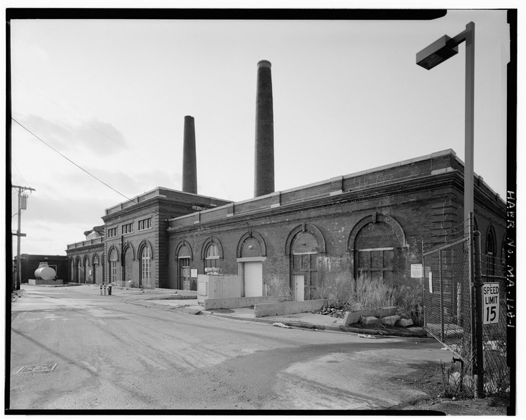
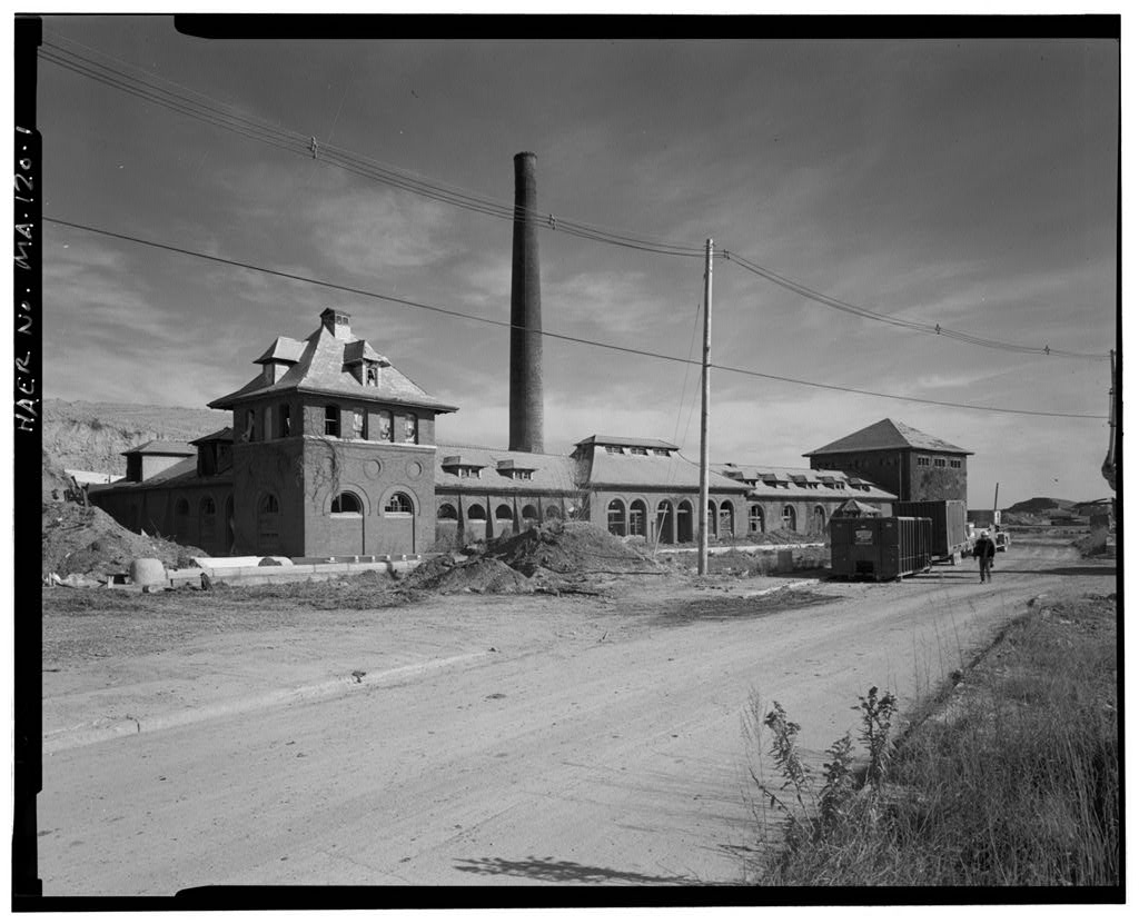
This documentation was extracted from the East Boston Pumping Station: Historical. Architectural. Structural and Geotechnical Assessment dated September 18, as prepared by Metcalf and Eddy in association with Ann Beha Associates. The assessment was completed in compliance with the National Historic Preservation Act (36 CFR and Ch. 9, ss. as amended CMR The Authority is proposing to demolish the two chimneys at the East Boston Steam Pumping Station (EBSPS) as an emergency response to public safety issues. The demolition of these chimneys would constitute an adverse effect (36 CFR and 950 CMR (a)) to the National Register eligible property.
The Massachusetts Historical Commission staff concurred that alternatives to demolition have been investigated and that repair or in-kind replacement was not prudent or feasible due to the severely deteriorated conditions and the excessively high cost of an in-kind replacement.
MHC accepted the adverse effect of the demolition of the two chimneys provided that the Massachusetts Water Resources Authority (MWRA) undertake documentation to Historic American Engineering Record (HAER) standards; the MWRA conduct an annual monitoring program of the physical condition of the building and undertake sufficient repairs to maintain the building such that future rehabilitation is not precluded; and that the MWRA actively explore feasible options for reuse of the EBSPS as the MWRA makes plans to vacate it.
The MWRA has agreed, subject to Section and other applicable provisions of the MWRA's Enabling Act, Chapter 372 of the Acts of to take all steps necessary to declare the EBSPS surplus to the current and future needs of the MWRA, to notify the Massachusetts Division of Capital Planning and Operations (DCPO) of the surplus status of the East Boston Steam Pump Station HAER No. MA - 128 (page 3) EBSPS and to work cooperatively with DCPO and the Massachusetts Historic Preservation Officer to elicit an acceptable proposal from interested parties for the rehabilitation and reuse of the EBSPS. In addition, the MWRA has agreed to prepare a marketing plan for the EBSPS.
Until such time as the MWRA has formally declared the EBSPS surplus to its current and future needs and has so notified DCPO, the MWRA has agreed to an annual monitoring program which will be conducted of the physical condition of the building and to undertake sufficient repairs to maintain the building such that future rehabilitation is not precluded until the transfer of the EBSPS facility. The MWRA has also agreed to secure and protect the EBSPS against damage until the measures agreed upon are implemented. A Memorandum of Agreement is pending execution between the Advisory Council on Historic Preservation, the U.S.
Environmental Protection Agency (Region I), and Massachusetts Historic Preservation Officer with the concurrence of the MWRA, Division of Capital Planning and Operations and the Environmental Protection Agency. East Boston Steam Pump Station HAER No. MA - 128 (page 4)
Page CHAPTER 1 - 1.0 GENERAL 7 CHAPTER 2- 2.0 BUILDING HISTORY AND SIGNIFICANCE 9 2.1 Introduction 9 2.2 The Significance of the East Boston Steam Pumping Station 9 2.3 Early History of Sewage Disposal in the City of Boston 13 2.4 Early History of the Metropolitan Sewerage System 14 2.5 Design of the Original East Boston Steam Pumping Station 15 2.6 Construction of the Original East Boston Steam Pumping Station 16 2.7 The Great Chelsea Fire of 19 2.8 The Rebuilding and Enlargement Program of 20 2.9 Ancillary Buildings on the East Boston Steam Pumping Station Site 21 The North and South Metropolitan Sewer Districts in 22 Alterations and Changes Made to the Building, 23 The Explosion and Destruction of the Screen House 23 Alterations and Changes to the Building, 24 CHAPTER 3- 3.0 EXISTING CONDITIONS 28 3.1 ARCHITECTURAL ELEMENTS 28 General Assessment 28 Roofs 28 Roof Skylights 32 Brick Masonry Walls 32 Roof Parapet Walls 37 Doors and Windows 39 East Boston Steam Pump Station HAER No.
MA - 128 (page 5) TABLE OF CONTENTS 3.2 STRUCTURAL ELEMENTS 40 Building Description 40 General 40 Original Station 41 Central Pavilion 42 Coal House 43 Screen House 43 Chimneys 44 Existing Conditions 46 Walls 46 Roof Slabs and Beams 48 Columns and Platform Beams in the Coal House ... 49 Foundation Wall 49 Floor Slab 50 Chimneys 50 3.3 GEOTECHNICAL ELEMENTS 52 General 52 Subsurface Information 52 Groundwater Conditions 53 Settlement Measurements 53 Visual Inspection 54 Foundation 54 Seawall 54 Pump Pits 55 Pipe Conduits 55 Boiler Room 55 Screen Room 56 Chimney Foundations 56 BIBLIOGRAPHY 57 East Boston Steam Pump Station HAER No. MA - 128 (page 6)
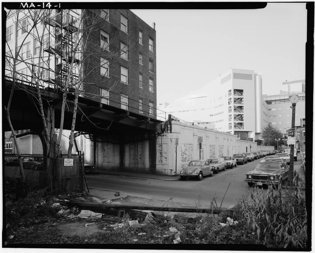
Table Page 3-1 Skylight Schedule 59 3-2 Door Schedule 60 3-3 Window Schedule 61 3-4 Transom Schedule 62 3-4 Transom Schedule (Continued) 63 3-5 Crack Descriptions 64 3-6 Chimney Crack Descriptions 65 3-7 Settlement Monitoring Record 66 LIST OF FIGURES Figure 3-1 Layout of the East Boston Steam Pumping Station 67 3-2 Crack Location Plan 68 3-3 Soil Profile Location Plan 69 3-4 Subsurface Profile A-A 70 3-5 Subsurface Profile B-B 71 3-6 Bench Mark Location Plan 72 LIST OF COPIES OF HISTORICAL PHOTOGRAPHS ILLUSTRATIONS: 1. East Boston Steam Pumping Station Circa 73 2. East Boston Steam Pumping Station Interior Circa 74 3. East Boston Steam Pumping Station - April 75 4. East Boston Steam Pumping Station Circa 76 MDC Photographs 5.
Northerly - East Side of Screen Building - South Side of Pumping Station 77 6. Northwesterly - East Side of Screen Building - South Side of Pump Station 78 7. Northerly - South Side of Pumping Station - August 79 8. South Side of Pumping Station - August 80 9. Westerly - East End of Building - August 81 10. Southerly - North Side of Building - August 82 11. Southerly - North Side of Building - August 83 12. Southerly - West End of Building - August 84 13. Southwesterly - General View - South Stack Used by Boiler 85 14. Southwesterly - North Stack - November 86 East Boston Steam Pump Station HAER No. MA - 128 (page 7) CHAPTER ONE 1.0 GENERAL The documentation for this report was extracted from the East Boston Steam Pumping Station Historical. Architectural.
Structural and Geotechnical Assessment, dated September 18, as prepared by Metcalf and Eddy in Association with Ann Beha Associates. The assessment was completed in compliance with the National Historic Preservation Act (36 CFR and Ch. 9, ss. as amended CMR The Massachusetts Water Resources Authority (MWRA) is proposing to demolish the two chimneys at the East Boston Steam Pumping Station (EBSPS) as an emergency response to public safety issues. The demolition of these chimneys would constitute an adverse effect (36 CFR and 950 CMR (a)) to the National Register eligible property. The report first presents historical data and the historical significance of the steam pumping station, followed by an evaluation of the existing conditions of the structure.
The existing conditions and repair sections have been subdivided into architectural, structural, and geotechnical sections. The Illustration portion of the report includes illustrative copies of historic photographs. Metcalf & Eddy was responsible for structural and geotechnical evaluations and recommendations for repair and retained the services of Ann Beha Associates to assist in the preparation of the historical, architectural, structural and geotechnical Assessment of the EBSPS. Ann Beha Associates prepared the chapter on building history and significance and was responsible for evaluating existing conditions of the building. East Boston Steam Pump Station HAER No. MA - 128 (page 8) The EBSPS is located at 20 Addison Street adjacent to the Chelsea Creek in East Boston.
Under the MWRA's Enabling Act, title to the EBSPS remains with the Commonwealth of Massachusetts with the provision that the MWRA has the right to use, operate and maintain the facility. The original structure was constructed during and and was rebuilt and expanded in following severe damage by the Great Chelsea Fire of The building consists of a screen house, engine room, boiler room and coal house. The station was permanently taken out of pumping service in replaced by the Ignatius Caruso Pumping Station, and is currently used as a machine shop and maintenance garage by the MWRA Sewerage Division. It is constructed of masonry bearing walls and steel framing encased concrete. East Boston Steam Pump Station HAER No.
MA - 128 (page 9) CHAPTER TWO 2.0 BUILDING HISTORY AND SIGNIFICANCE 2.1 Introduction The East Boston Steam Pumping Station (EBSPS) is operated by the Massachusetts Water Resources Authority (MWRA) and is located at 20 Addison Street in East Boston, adjacent to the Chelsea Creek. The Ignatius Caruso Pumping Station, completed and put into service in occupies a site immediately south of the EBSPS. The newly constructed pumping station replaced the EBSPS which was decommissioned from service and is now used primarily as a MWRA maintenance facility. The original EBSPS was constructed in as one of three state-of-the-art pumping stations in a then new Metropolitan Sewerage System.
The EBSPS was severely damaged in the Great Chelsea Fire of and was expanded and rebuilt in An explosion in the screen house in destroyed that portion of the pumping station and resulted in the enlargement and rebuilding of the screen house portion of the facility. The present EBSPS has remained essentially unchanged since that time. 2.2 The Significance of the East Boston Steam Pumping Station To date, the EBSPS has not been nominated for inclusion in the National Register of Historic Places. However, in a December 20, letter to the MWRA from Massachusetts Historical Commission Staff Architect, Paul Holtz, MHC determined that the building is eligible for listing in both the State and National Registers of Historic Places.
The National Register includes properties determined to have significance at the National, State and local levels. East Boston Steam Pump Station HAER No. MA - 128 (page 10) The EBSPS is strongly associated with the emergence of public health as an important concern of State government beginning with the establishment of the Metropolitan Sewerage Commission in Metropolitan Boston was one of the first urban areas in the United States to design and build a comprehensive system of intercepting sewers to protect the health of its citizens. Boston was also the first city to provide a centrally planned and controlled water supply to all parts of the metropolitan area.
The EBSPS is significant as one of the vital components in regulating the daily movement of sewage in the North Metropolitan Sewerage District. The Metropolitan Sewerage Commission was one of the two earliest special bureaucratic agencies organized in the United States to oversee the collection and disposal of sewage. Both it and the Chicago Sanitary District, were established in Although sewage generally flows by gravity through sewers, pumping sometimes is required. Pumping may be the most economical means of conveying sewage past a hill, or the only way to get from a low point to a main sewer at a higher level.
Pumping stations, or lift stations, are used when it is necessary to pump sewage to a higher level The pumping station may be under or above ground, housed in a building, large or small. The pumps are protected against debris in the sewage by screens located in a screen room. The design of the EBSPS is significant as it relates to the engineering processes contained within its interior. The monumental scale and size of the pumping station reflects its standing as an important municipal edifice and as a document of turn-of-the-century hydraulic engineering. Similar to the MWRA's Charlestown and Deer Island Pumping Stations, the original EBSPS was designed by architect Arthur F. Gray. All three pumping stations shared a very similar design concept.
The engine rooms were typically two-story spaces with exposed steel trusses and were ventilated and illuminated by roof-top dormers. Roofs were covered in slate and embellished at ridges East Boston Steam Pump Station HAER No. MA - 128 (page 11) and hips with glazed terra cotta tiles, presenting a picturesque profile. Walls were typically red brick and window and door openings were further articulated with rubbed and moulded brick. Terra cotta was used to give added detail to the impost blocks of arches. A massive brick chimney clearly identified each building's industrial function. The scale of the chimney and its attached engine room was a strong gesture in proclaiming the civic importance of each pumping station.
The engines and walls of the EBSPS survived the Great Chelsea Fire of to an extent which allowed the structure to be stabilized and enlarged to assume even greater pumping responsibilities. Stylistically, the building was upgraded with such modern features as a flat roof with concealed interior roof drains. The picturesque asymmetry of the original pumping station's profile was replaced with a rigidly symmetrical Beaux Arts Revival silhouette, enhanced through the use of Roman clerestory lights in the central pavilion. A second chimney stack, placed in a mirror-image location in relation to the first chimney, was added to impose further balance to the design. The existing west wing, however, retains the original placement of windows, enlarged in height by approximately five feet.
Edwin Reynolds of the Edward P. Allis Company was a nationally recognized mechanical engineer and designer of large steam machinery. His horizontally-lying, vertical-shaft centrifugal pumping engine, later promoted and sold as the "Boston Type", is an ingenious design which allowed for slower speeds and locating the engine much nearer to the source of supply. This type of pump became a prototype for use elsewhere in the country. According to Robert M. Vogel, Curator of the Division of Engineering and Industry at the Smithsonian Institution in Washington, the low-head, centrifugal sewage pumping engines surviving in Boston are the only examples of their type in the country.
The EBSPS contains one of its original triple-expansion steam engines, the only surviving example of this particular type of steam engine. Similar engines used East Boston Steam Pump Station HAER No. MA - 128 (page 12) to exist in the Deer Island and Charlestown Pumping Stations, but were removed in the The triple-expansion steam engines were used to power four horizontally-oriented, Edward P. Allis centrifugal pumps. The steam engine and centrifugal pump were functioning components of the EBSPS and were used to pump excess rainwater during heavy storms. In addition, the EBSPS itself would yield important information relating to both hydraulic and civil engineering history.
Since the pumping stations at East Boston, Deer Island and Charlestown still survive mostly intact, the public, as well as students of hydraulic and civil engineering, have an opportunity to view and investigate the major components of a large-scale municipal sewerage system. Finally, the EBSPS exhibits strong integrity of location, design, setting, materials, workmanship, feeling and association. The neighborhood surrounding the pumping station has been used for industrial and fuel storage purposes throughout the life of the building and that context will apparently continue for the foreseeable future. The location of the pumping station, abutting Chelsea Creek, gives it a strong connection to the water.
The water was utilized in the steam production process as well as in the transporting of the coal to feed the pumping station's boilers. Due to its location, the EBSPS was damaged by the Great Chelsea Fire of It was subsequently rebuilt utilizing the original walls in an expanded new building. In summation, the EBSPS contains rare pumping machinery designed and fabricated by a nationally recognized leader in the manufacture of steam pumping equipment. Before its enlargement in the pumping station was one of the original elements of the Metropolitan Sewerage District.
Architecturally, it has a very strong image, which is further enhanced by the rich embellishment of its brick walls with articulated window and door openings, corner quoins, a classically detailed main building cornice, and the East Boston Steam Pump Station HAER No. MA - 128 (page 13) powerful verticality of the twin chimney stacks. The EBSPS has made a significant contribution to the broad patterns of our history and embodies the distinctive characteristics of a type, period and method of construction and which has yielded information important in history.
23 Early History of Sewage Disposal in the City of Boston A number of privately-owned sewer systems had been in operation in Boston since after the Civil War, but the City and the metropolitan area lacked any overall plan for the systematic removal of sewage. Several attempts were made by the State Legislature to study and prepare a plan for a metropolitan sewerage system, but political infighting over financing prevented the project from moving forward. The City of Boston finally was took matters into its own hands and created a commission to prepare a plan their own plan. The Boston Improved Sewage Commission recommended the building of two separate sewerage systems, one on each side of the Charles River. However, the City Council voted to fund only the southern system.
Between and the Commission built a series of intercepting main sewers to receive sewage from a variety of existing sources along the south side of the Charles River. At Old Harbor Point, the City erected its first sewerage pumping station, the Calf Pasture Pumping Station, in This station pumped sewage to a holding facility on Moon Island and from there it flowed by gravity into Dorchester Bay. A Boston guidebook from King's Handbook of Boston, noted that at that time Boston had approximately 180 miles of sewers. East Boston Steam Pump Station HAER No.
MA - 128 (page 14) 2.4 Early History of the Metropolitan Sewerage System (now known as the Massachusetts Water Resources Authority Sewerage System) The Board of Metropolitan Sewage Commissioners was created by an Act of the State Legislature in The original Board was composed of three members empowered by the Legislature to "construct, maintain and operate" for the cities of metropolitan Boston "such main sewers and other works as shall be required for a system of sewage disposal for said cities and towns".
The first Annual Report of the Metropolitan Sewerage Commissioners was issued October 1, The original Metropolitan Sewerage Works consisted of three separate sewerage systems, or groups of main intercepting sewers: the North Metropolitan System, the Charles River System, and the Neponset River System. The North Metropolitan System was primarily located in the Mystic River Valley with its final outfall at Deer Island in Boston Harbor. It was the largest system in the Metropolitan Sewerage Works consisting of over 46 miles of main and branch lines of intercepting sewers. The system began at a point between Stoneham and Woburn, some 18 miles from its final outfall at Deer Island.
The main sewer eventually passed under Chelsea Creek intercepting East Boston flows from the branch sewer at the south shore of Chelsea Creek. At this point, the EBSPS raised the combined sewage approximately 19 feet. The sewer continued on under Belle Isle Inlet, traversed Winthrop to Shirley Gut, and then flowed to the pumping station on Deer Island. Depending on tides, the steam pumps on Deer Island raised the sewage from 11 to 20 feet and deposited it to an outfall sewer. The foot long outfall sewer discharged directly into the ocean at a point near the Deer Island light house. The Charles River System served the communities of Waltham, Watertown, Brighton, most of Newton and Brookline, and part of Boston's Back Bay. The system consisted of approximately 8 miles of intercepting sewers.
The main sewer line began in Waltham East Boston Steam Pump Station HAER No. MA - 128 (page 15) and generally followed the southern boundary of the Charles River. At the corner of Gainsborough Street and Huntington Avenue, the main sewer joined the sewage flow of the Boston Main Drainage Works. The Neponset Valley System was constructed to serve the residents of West Roxbury, Dedham, Hyde Park, Milton and Dorchester. Portions of Newton and Brookline which could not be connected to the Charles River System appear to have been added to the Neponset Valley System sometime shortly after At that time, the system consisted of approximately 10 miles of intercepting sewers. The upper end of the system was located on Weld Street in West Roxbury near the Brookline town line.
From there, the sewer travelled in a southern direction to the Brookline waterworks after which it followed the north shores of the Charles River, Mother Brook and the Neponset River through the communities of West Roxbury, Dedham and Hyde Park. The system ended at the Calf Pasture Pumping Station in Dorchester where sewerage was discharged into Boston Harbor at Moon Island. Construction of the three sewer systems began in and all systems were in operation by In the Charles River and Neponset River Systems were combined to form the South Metropolitan Sewerage District. By the North Metropolitan District was serving an area of square miles with a total population of some residents.
The new South Metropolitan District covered a larger area, square miles, but served a smaller population of people. 2.5 Design of the Original East Boston Steam Pumping Station The architect for the original EBSPS was Arthur F. Gray of the Gray and Blaisdell firm. Arthur F. Gray was born in Beverly, Massachusetts on January 9, and was a East Boston Steam Pump Station HAER No. MA - 128 (page 16) descendent of two Revolutionary War officers. He made his home in Watertown with his wife and two children. Information in the Architects' File at the Boston Public Library indicates that the Gray and Blaisdell firm was in existence from Their offices were located in the Exchange Building at 53 State Street in Boston.
After Gray appears to have practiced on his own until approximately An advertisement in the Boston City Directory described his practice as follows: Textile Mills, Mechanical, and Industrial Plants designed; Erection supervised and equipment arranged; Valuations and reports on the reorganization of existing plants; Consulting engineer for existing industries. A later advertisement in described his practice as specializing in "school houses, mercantile buildings, industrial plants, and warehouses".
In addition to designing the pumping stations at East Boston, Charlestown and Deer Island, documentation exists for at least three of his other commissions: the Reversible Collar Company factory building located in Cambridge, an office building located at 363 Boylston Street in Boston, and a Casino at Riverton Park in Portland, Maine. In Gray joined a partnership with four other architects and moved to the Richards Building located at 114 State Street. The following year Gray ceased to be listed in the Boston City Directory. His early career included work on many industrial and textile plants in Ohio and Massachusetts. Before beginning his practice in Boston, Gray was the resident engineer for the manufacturing firm of Alexander Smith & Sons in Yonkers, New York.
2.6 Construction of the Original East Boston Steam Pumping Station Bids for the pumping equipment of the EBSPS were opened on July 1, The successful contractor was the Edward P. Allis Company of Milwaukee, Wisconsin with a bid of The same company was also successful in securing the contracts for the fabrication of the pumping equipment for the Deer Island and Charlestown Pumping Stations. East Boston Steam Pump Station HAER No. MA - 128 (page 17) A bid opening was held on April 14, to select the contractor to build the new East The successful bidder was Edward E.
Stout of with a bid of The new pumping station was described as follows: A building of brick, granite and terra-cotta, containing an engine room 100 feet by 31 1/2 feet, and boiler room 100 feet by 31 1/2 feet including toilet and tool rooms, economizer, etc. A chimney 125 feet high, with 4 feet 6 inches flue. The station will contain two pumping engines, boilers, etc. described in last year's report. The original construction contract for the EBSPS did not include any of the foundation work which was undertaken by day laborers under direct contract to the Metropolitan Sewerage Commission.
The foundation work included connecting the station to the incoming sewer lines, the building of the screen chamber, the suction conduit, the pump-wells, the discharge channels, the boiler and chimney foundations, the sea wall along Chelsea Creek and the main building foundations below grade level. The stone sea wall was constructed along Chelsea Creek and runs for approximately 165 feet. It was 10 feet wide at its base and 4 feet wide at its top, which was 16 feet above low water. The wall was constructed of split-face granite with a face batter of 1 in 8. Portland cement concrete was used in setting the granite in place. This original wall still remains, but is now obscured by a veneer of reinforced concrete.
The original chimney foundation was also built of split granite, laid in courses, and was described as being: 20 feet square at low water, 16 feet square at bottom of brickwork, and is 16 feet high. Before laying of any stone the surface of the ground was compacted by dropping on it from a height of about 3 feet a pile hammer weighing pounds. After going over the surface thoroughly this way, a layer of concrete 6 inches thick, mixed with very little water, was rammed in same manner. On this foundation the stone-work was started. Beginning in May of the work of building the pumping station and installing the pumping equipment were undertaken concurrently. By September both pumps had Bast Boston Steam Pump Station HAER No.
MA - 128 (page 18) been installed and work was proceeding on the engines. The chimney was also completed at this time as were all the walls and roof. The original roof was framed with iron trusses and sheathed with wood. Red slate, terra cotta ridge and hip rolls, and copper flashing completed the roofing work. Work completed in included the installation of plumbing and toilet rooms, flooring, and miscellaneous finish materials. In October of Arthur F. Gray prepared drawings to add a screen room to the southeast corner of the engine room. The size of this addition was 19 feet long by 18 feet 2 inches wide. Its roof was also covered with red slate, and had terra cotta ridge and hip rolls to match the main building.
Construction of the screen house commenced on July 1, Construction of a wood coal-pocket 54 feet long and 32 feet 6 inches wide began on June 24, and was completed by late September. The building was located at the east end of the pumping station and was designed to hold 600 tons of coal. The red slate roof of the coal pocket matched the pumping station. The total cost of constructing the East Boston Pumping Steam Pumping Station, including all machinery, the screen house and the coal-pocket, was The finished station was certified as being capable of pumping 90 million gallons of sewerage every 24 hours. The next major work undertaken on the building occurred in when a third pumping engine was added. Additional boilers were also installed at this time.
East Boston Steam Pump Station HAER No. MA - 128 (page 19) 2.7 The Great Chelsea Fire of In the State Legislature appropriated to enlarge the East Boston Steam Pumping Station over a period of three years. This action was necessary to accommodate the additional pumping requirements of the North Metropolitan System which had seen the addition of some new customers between and However, a massive fire destroyed much of the city of Chelsea on April 12, Firefighters at the pumping station were able to successfully defend the station for most of the day, until a barge of flammable materials blew up in Chelsea Creek near an adjoining oil works. Burning oil was carried by the incoming tide up and around the pumping station. Flames quickly reached up to the wood doors, windows and roof.
The Eighth Annual Report of the Metropolitan Water and Sewerage Board for includes both an interior and an exterior view of the fire-damaged building. The report describes the damage as follows: The fire entirely destroyed roofs, doors, windows, coal house and wharf at this station. The girders and most of the piping of the station were a mass of twisted iron and steel. The walls were scarred and cracked and had fallen in places. A subsequent examination of the building by experts indicated that the foundations and walls were stable enough to cover with a light, temporary roof. An examination of the machinery indicated that pumps, steam cylinders and boilers had not been greatly injured.
Between April 13 and April 27 a temporary wooden roof, doors and windows were placed by Woodbury & Leighton, builders. While the temporary roof was being placed, necessary repairs to one engine, piping and two boilers were made by the engineers of the works. East Boston Steam Pump Station HAER No. MA - 128 (page 20) 2.8 The Rebuilding and Enlargement Program of After a review of the anticipated future needs of the North Metropolitan System, the Metropolitan Water and Sewerage Board decided to enlarge the East Boston Steam Pumping Station, as the Legislature had recommended before the fire. In August of a contract was let with the firm of Woodbury & Leighton to repair the existing fire-damaged pumping station, make extensions to the boiler and engine rooms, and build a new coal house.
The following items summarize the scope of work undertaken during the years 1. Building to be enlarged to 268 feet in length and 65 feet in width. 2. All construction to be fireproof, with concrete roof and floors, masonry walls, steel doors and window frames. 3. New exterior walls to be brick, laid largely in Portland cement mortar, with granite trim. 4. Existing exterior masonry walls to be refaced with 4 inches of new brick, laid in Portland cement mortar and securely bonded to the old walls. A new granite base and granite trim to be added at new brick masonry. 5. Existing foundation wall along Chelsea Creek side of existing pumping station was badly scarred and cracked during Chelsea fire.
A new veneer of reinforced concrete (8-inch thick at the top, 1 foot 4-inch thick at the bottom) is to be anchored to the face of the existing wall and the two walls grouted together. The concrete reinforcement is to be continuous from 2 feet below the bed of the creek to the top of the existing foundation walls. 6. Foundation of screen-house to be strengthened through insertion of additional girders. Bearing and supporting beams of screen-house to be encased with concrete. 7. Air space cavity in Chelsea Creek side of existing pumping station to be grouted solid for full height of original exterior masonry wall. 8. Existing window and door openings along north, south and west facades of existing building to be increased in height approximately 5 feet.
East Boston Steam Pump Station HAER No. MA - 128 (page 21) The architect for the major expansion of the pumping station is unknown. The set of 14 sheets of working drawings prepared for the repair and expansion work are uniformly and prominently labeled "Metropolitan Water and Sewerage Board, Metropolitan Sewerage Works", May, Each sheet in the set is signed by William M. Brown, Chief Engineer of the Sewerage Works. It is not unreasonable to conclude that engineers employed by the Board designed and detailed the work. The new main engine room floor was installed in and consisted of steel-framed beams encased in concrete and covered with a slab of reinforced concrete.
Contracts for the above work were completed by November 1, A contract for a new wharf with steel coal runs was made with the John T. Scully Foundation and Transportation Company on July 15, and the basic framing work was completed on November 30, The new wharf was built along the entire Chelsea Creek side of the remodelled pumping station. It was 40 feet in width at its eastern end and varied elsewhere from 10 to 20 feet in width. The construction materials included spruce piles and spurshores, oak fender piles, a capping of steel channel irons, and diagonal braces of angle iron. To fireproof the entire wharf, reinforced concrete was poured around all piles and all steel frames.
This work was completed in the spring of 2.9 Ancillary Buildings on the East Boston Steam Pumping Station Site Several ancillary buildings have existed on the EBSPS site until very recently. In foundations were laid for a new stable and locker building at the corner of Addison and Chelsea Streets. The new building was 28 feet deep and 65 feet long, two stories high, and was erected to replace the earlier stable and locker building destroyed in the Great Chelsea Fire of East Boston Steam Pump Station HAER No. MA - 128 (page 22) The Metropolitan Water and Sewerage Board's Annual Report for contains a black and white photograph of the completed EBSPS. The photograph also shows the new stable and locker building, built approximately 75 feet directly west of the screen house.
It was built of reinforced concrete, was large enough to hold five horses and contained the headquarters for the repair and maintenance forces of the North Metropolitan System. A new small structure was built in the existing stock yard on Addison Street in The Annual Report for that year described it as a one-story masonry building with a concrete roof 13 feet wide by 30 feet in length. The new building was intended to be used as stock and pattern building. It was constructed entirely by the in-house maintenance staff. The North and South Metropolitan Sewer Districts in With the construction of the EBSPS virtually complete by the end of it is beneficial to review the overall growth and development of the Metropolitan Sewerage System up until that time.
By the North Metropolitan System had grown in size to contain miles of interceptor sewers and miles of local sewers. The system served 9 cities and 8 towns covering an area of square miles and a population of with a pumping station on-line at East Boston, Charlestown, Alewife Brook and Deer Island. By the South Metropolitan System had also grown in size to contain miles of interceptor sewers and miles of local sewers. The system served 4 cities and 4 towns covering an area of miles and a population of with a pumping station on-line at both Quincy and Ward Street. East Boston Steam Pump Station HAER No. MA - 128 (page 23) Alterations and Changes Made to the Building, In a new tile floor was installed in the new engine room and the old boilers from the original building were removed.
The space originally occupied by the boiler room was rearranged to provide space for new offices, toilets and work rooms. In a contract was awarded to enlarge the existing Screen House at the west end of the building and work commenced on July 23, By the time of the publication of the Metropolitan Water and Sewerage Board's Annual Report for that year, work had been completed on a new concrete and masonry by-pass and a new screen-chamber with cast-iron screen guides. Two drawings dated November, exist for the expansion of the Screen House structure. The Annual Report for makes no mention of the screen house work but the structure was apparently completed.
The dimensions of the newly expanded Screen House match those later described in the repair work of The only maintenance work undertaken in involved the application of a cement stucco, placed over metal lathing, to cover the fire-damaged interior walls of the original engine room. The stucco was then scored to match the brick masonry walls in the newer portion of the engine room. This work is visible today in the southwest corner of the Engine Room, where the rusting and sagging of the metal lath is creating horizontal cracks where the sheets of lath end. The Explosion and Destruction of the Screen House The new Screen House was totally destroyed by an explosion on June 1, during routine cleaning of the sewer walls below.
Gasoline fumes apparently had entered the sewer from an off-site source. A violent explosion resulted from the ignition of the East Boston Steam Pump Station HAER No. MA - 128 (page 24) fumes during the cleaning process. Six of the men in the Screen House were killed and two were seriously injured. The Screen House was entirely destroyed by the explosion; its walls were entirely blown off their foundations and landed some 20 to 40 feet away. Approximately one-half of the steel windows and doors and six skylights of the main building were either blown out or rendered inoperative. In addition, new glass had to be installed in seven roof monitors.
Separate contracts were let to repair the damaged windows and doors, repair the damaged skylights and roof monitors, and to construct an entirely new Screen House. The new Screen House was 39 feet by 48 feet and built of brick and Deer Island granite to match the main building. The design work was carried out by the engineering staff of the Metropolitan Sewerage Works and survives today as a set of two drawings dated September, Alterations and Changes to the Building, During extensive modifications to the roofs over the coal storage room and the original engine room wings were accomplished. The roof slope was slightly increased in both locations and the original clay tiles on both surfaces were removed and relaid in a new Portland cement mortar.
Expansion joints were also installed and were filled with an elastic cement. The new Screen House was completed on February 28, except for the floor which was finished shortly thereafter by the in-house maintenance staff. In a new two-story masonry locker was installed inside the pumping station at the east end of the engine room. This locker was for the storage of general pumping station supplies. East Boston Steam Pump Station HAER No. MA (page 25) Two noteworthy items completed during the year were a new basement and reconstruction of the "south" chimney. First, a new basement was constructed from the west end of the pumping station up to the pit of the Number 3 engine. Evidently, this work was undertaken to more readily repair pipes and conduits which had previously been inaccessible.
Second, the "south" chimney was partially rebuilt. We have assumed that the south chimney being discussed is in reality the eastern or more recent chimney dating from A large crack had opened up approximately 18 feet below the top of the chimney. Scaffolding was erected and the upper portion of the chimney was removed and rebuilt. The remainder of the chimney was completely repointed. During the original chimney also needed work to repair years of exposure to weathering. The cast iron ring at the top of the chimney was renewed with new points on the lightning rods and the masonry of the chimney was repointed both on its exterior and interior surfaces throughout its upper portion.
The next major work undertaken at the EBSPS occurred in At this time, the brick wall at the east end of the machine shop was moved approximately 9 feet east of its original location to give more room for new machinery in the shop. The adjoining mens' locker and dressing room was correspondingly reduced in size. At the same time, a new reinforced concrete floor and ceiling were introduced over the mens' locker and dressing room to provide a loft for the placement of additional shop equipment. A new stair was added to give direct access to the loft from the machine shop space below. The original tile roof installed over the engine room, machine shop and offices was entirely removed in This roof corresponds to the original footprint of the building, the present western wing of the station.
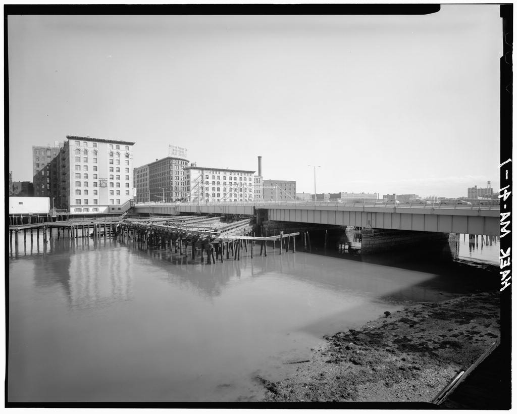
The new roof consisted of built-up layers of asbestos and asphalt roofing plies mopped together. Another work item for included the replacement of all of the exterior steel doors along the south side of East Boston Steam Pump Station HAER No. MA - 128 (page 26) the building. The existing doors were installed during the reconstruction of the pumping station and after the explosion in The doors had become badly corroded and were replaced with new doors consisting of a wood core over which lead-coated copper had been attached. A new Chelsea Creek bridge was constructed by the City of Boston just west of the pumping station during This work necessitated the demolition of all of the ancillary pumping station buildings formally on that site, except for the concrete locker and stable building.
This building was moved onto a new foundation just south of the existing pumping station, on the opposite side of Addison Street, and survived until when the new Ignatius Caruso Pumping Station was being constructed. No further significant improvements were made to the pumping station until During August of a comprehensive building evaluation and photographic survey was made of the facility by the Metropolitan District Commission to determine maintenance requirements. Later photographs reveal that both chimneys underwent major repointing and repair work during Photographs taken in November of show that the west chimney was repointed over perhaps 80% of its surfaces and that the east chimney was repointed over perhaps 25% of its surfaces.
From the photographs, it is also clear that both chimneys were reduced in height by approximately 12 feet at this time. The Metropolitan District Commission photographic illustrations document the conditions of the site surrounding the pumping station in They are the only materials which document the size and appearance of the concrete wharf which used to abut the pumping station along its eastern and northern sides. According to files at the EBSPS, the wharf was demolished in East Boston Steam Pump Station HAER No.
MA - 128 (page 27) In August of the City Council of Boston authorized the City to build a new sewerage system at a projected cost of Completion of the new system was scheduled for and was to include 13 miles of new intercepting sewers, a new pumping station and pumps at Old Harbor Point in Dorchester, and a holding area and outfall tunnel on Moon Island (King, p. The National Register Nomination Form, on file at the Massachusetts Historical Commission, which was prepared for the Calf Pasture Pumping Station, indicates that was actually expended to complete the above work (Kottaridis, p. East Boston Steam Pump Station HAER No. MA - 128 (page 28) CHAPTER THREE 3.0 EXISTING CONDITIONS 3.1
General Assessment The exterior of the East Boston Steam Pumping Station (EBSPS) was inspected and evaluated during a number of site visits made during late May and early June of The architectural survey's primary focus was the exterior masonry shell of the building, as well as the roof and its skylights. However, some time was spent reviewing interior conditions in an effort to confirm or better understand problems on the exterior. John Markley, the superintendent of the facility, was interviewed and provided an informative tour of the facility, pointing out some past and present deficiencies. Wide field-of-view binoculars were used to visually survey all of the facades of the building. A boat was obtained from the MWRA to inspect the Chelsea Creek side of the building.
The equipment within the building has typically received the bulk of funds for ongoing maintenance and repair. This is evident from examining some 40 years of Annual Reports issued by the Metropolitan Water and Sewerage Board, as well as viewing the current state of the fabric of the building. Most obvious is the serious lack of maintenance expended upon the roof and parapets of the building. The resulting saturation of certain wall areas has promoted the accelerated weathering and decay of large portions of brick masonry wall areas below. Roofs The exterior of the building has received minimal maintenance over the last fifty years. The most serious lack of maintenance has occurred at the roof. The present roof East Boston Steam Pump Station HAER No.
MA - 128 (page 29) membranes probably date from and appear to have only been patched as leaks became evident. Currently, the roof membranes are completely inadequate and many decades beyond their useful life. Review of the original drawings from indicates that the existing roof system is composed of a heavily-reinforced concrete slab and that the original weathering surface was exposed terra cotta tiling. The individual tiles, approximately 6-inch by 9-inch, were set in an asphalt mastic over a Portland cement setting bed. The joints surrounding each tile were then grouted. This design suffered from the incredible length of joints which had to be kept watertight. It was a system that would have required regular maintenance to retain its water shedding integrity.
As early as the tiling was removed on all three roofs and the pitch of the concrete substrate was increased. The tiling was then reinstalled in a new Portland cement mortar bed and expansion joints were provided which were filled with elastic cement. By the roofs over the western wing and the central pavilion had decayed to such an extent that the tiling was completely removed and replaced with new built-up roofs consisting of asbestos and asphalt felts mopped together and surfaced with an aggregate material. The existing built-up roofs on both wings as well as the central pavilion are seriously deteriorated. Surfaces are cracked and fissured, lap joints between felts have opened up, many areas are soft and spongy when walked on, and evidence of many spot repairs is apparent.
The metal base flashing and counterflashing on all roofs is typically copper, but in many locations it is missing or seriously corroded. Roof penetrations such as steam vents and other stacks rely on pitch pockets or seriously deteriorated flashing to resist water penetration. The original tile roof over the eastern wing, or coal house, remains in place. At some undetermined point, a built-up roof membrane was applied directly over the tiling. This East Boston Steam Pump Station HAER No. MA - 128 (page 30) membrane appears to composed of a fiberglass base sheet, with additional felts applied on top. The membrane is disintegrating and separating and in several locations one may glimpse the tiling below.
The original roof drains and interior downspouts are clogged, missing drain covers or have failed due to advanced corrosion. Inspection of the original drawings indicates that the two wings and central pavilion originally had roof drains in each of their corners. The drains were connected to 4-inch diameter wrought iron conductors or internal downspouts, which in turn emptied into 6-inch diameter drain lines located beneath the floor slabs of the building. The drain lines penetrated the north face of the building and discharged directly into Chelsea Creek. The original roof substrate lacks the proper slope to adequately drain any of the roofs.
Examination of the original roof framing drawing reveals that the steel roof framing was installed with a slope of only 3/16-inch over the 32 feet from the center of the roof to the corner roof drains on both wings. At the roof of the central pavilion, a slope of only 1/2-inch over the 37 feet from the center of the roof to the corner roof drains was specified. Modern built-up roofs with aggregate ballasts may typically slope up to a maximum of 1/2-inch per foot The attempt to increase the pitch of the roof was apparently not successful, for in the roofs over the western wing and the central pavilion were replaced with new built-up roofs.
The relatively small distance between the roof surface and the sill of the clerestory windows in the central pavilion, remains a serious constraint in increasing the pitch of the roofs on the two wings. The lack of adequate slope is a serious and continuing problem with all of the roofs. Ponding of water is a current problem at the northeast corner of the east wing. A clogged roof drain approximately one foot from the corner has caused a substantial amount of water to collect. Perhaps, it is no coincidence that the exterior masonry wall East Boston Steam Pump Station HAER No.
MA - 128 (page 31) below this roof drain, at the eastern facade of the coal house, has suffered considerable separation of its facing brick from its back-up wythes, and exhibits a pronounced outward bulge of approximately 6 to 8-inches. The condition of the various existing concrete roof slabs is unknown. However, the drawings indicate that square, twisted steel reinforcing bars ("Ransome" bars) were installed in all of the roofs. These bars were placed as closely as 7 to 9-inches on center, perpendicular to the primary roof framing, and from 1-foot 7-inches to 3-feet on center, parallel to the primary roof framing. Any roof replacement work should also involve a careful inspection of the condition of both the concrete deck and any visible damage to the embedded steel reinforcement.
The roof slab also lacks any provision for expansion at its outer edge. Any horizontal increase in the size of the roof slab would result in a displacement of the granite cornice elements on the exterior face of the building. Examination of the drawings reveals that the edge of the concrete roof slab coincides vertically with the inside face of the roof parapet at the complete perimeter of the eastern wing, the east and west parapet walls of the central pavilion, and the west parapet wall of the western wing. At the other parapet locations, the concrete roof slab coincides vertically with the outside face of the parapet wall.
Failure of the roof base flashing would allow water from the roof to directly enter the main wall below and potentially corrode the ends of the steel framing of the roof. Saturation of the wall area below the steel framing may also be possible and may explain areas of moderate to severe damage to brick masonry at these locations. Where the concrete slab coincides with the outside vertical face of the parapet, the potential for water penetration is also possible. At this location, the roof parapet overlaps the joint between the granite cornice and the concrete roof slab by only an inch or two. Failure of the mortar bed at the base of the parapet wall, or any outward East Boston Steam Pump Station HAER No.
MA - 128 (page 32) movement of the granite cornice, would allow water to penetrate downward into the masonry wall between the joint of the concrete roof slab and the granite cornice. Roof Skylights The existing skylights appear to be a combination of units probably dating from and Skylights made with aluminum framing appear in the MDC survey photographic illustrations taken in and and may date from the late or All of the existing skylights exhibit varying combinations of corrosion, broken or missing glass, or leakage along their perimeter curbs. Metal flashing and counterflashing along the perimeter of many of the skylights is seriously corroded or missing.
From the inside of the building, one may observe that the steel beams embedded in several curbs have rusted and expanded causing displacement of the curbs. In the boiler room, maintenance workers erected metal hoods to shield electrical equipment and chemicals from what must have been a chronic problem: dripping water leaking from the old skylights above. On the roof of the central pavilion, directly over the boiler room, two large skylights originally 9-feet 5-inches by 41-feet 4-inches, have been replaced by wood enclosures covered by asphalt roll roofing. The enclosure next to the north parapet predates the adjoining enclosure dates from and replaced a skylight visible in one of the MDC photographs. Two skylights over the eastern wing have been replaced in a similar manner.
A schedule of the skylights with a description of their condition is provided in the Skylight Schedule (Table Brick Masonry Walls The lack of proper roof maintenance is certainly evident at the roof level but the most serious damage done to the building has occurred in the exterior masonry walls. Here, East Boston Steam Pump Station HAER No. MA - 128 (page 33) one is aware of widespread damage to the brick due to the continuing saturation of most walls, with water entering from the roof and parapets above.
Commonly observed conditions include the surface spalling of brick due to freeze/thaw cycles or sulfate attack in the surrounding mortar, surface efflorescence/subflorescence of soluble salts, build-up of surface deposits caused by the repeated flowing of water from the interior of the walls, separation of the face wythe of brick from its back-up wythes resulting in a noticeable bow in the wall in at least one location, and the rusting and expansion of embedded steel causing flat brick arches to split moving outward and downward. Efflorescence is typically not a serious problem and is usually removed with simply a water spray coupled with hand brushing of the affected surface.
However, at the EBSPS, the soluble acids carried by the water penetrating from the roof above appear to be crystallizing or subflorescing slightly behind the surface of the brick. The evaporation of the penetrating water results in the formation of salt crystals, which expand as they The expansion process results in the destruction of the structure of the brick. If the source of water continues, the destructive subflorescence process also continues until individual brick units may eventually have only their perimeter mortar remaining. It is interesting to observe the evidence of efflorescence and subflorescence along the length of the south facade of the pumping station. The central pavilion totally lacks any areas of major efflorescence, subflorescence or brick spalling.
However, the two flanking wings are both severely discolored and damaged by both efflorescence and subflorescence. Closer inspection of the west wing reveals that water from the roof has periodically wetted the wall areas as far down as below the bottom sash of the double-hung windows. These lower wall areas exhibit surface efflorescence but relatively little spalling of brick. Serious spalling of brick masonry begins generally at the level of the springing of the ornamental brick arches over each window and continues upward to the underside of the granite cornice. This area of the wall is the section which is being East Boston Steam Pump Station HAER No. MA - 128 (page 34) severely saturated with water on a regular basis and which is suffering many of the consequences.
The east wing is in even worse condition than the west wing. Perhaps, this is due to the fact that this wing was only used for coal storage and was never heated as an occupied space. Here, efflorescence, subflorescence, and major brick spalling extends all the way down to the granite water table. Cycles of freezing and thawing may also occur within the exterior masonry during the winter season. Typically, one observes this activity when a wind-driven rain saturates a brick masonry wall and is quickly followed by a drop in the temperature to below the freezing point. The trapped moisture freezes and expands greatly causing the destruction of the brick to the depth of the original water penetration.
This process may be occurring at the pumping station, but the source of the water would appear to be primarily from the roof and parapet above. Another probable process of destruction found at the EBSPS, is sulfate attack in the Portland cement mortar which was originally used in the placing of the brick masonry. Water penetrating from the roof or parapets carries soluble salts which may react with the tricalcium aluminate present in Portland cement mortars. The interaction which takes place causes a substantial increase in the volume of the mortar causing the vertical height of the wall to expand. Because the mortar encapsulates each brick unit, expansion of the mortar may also cause spalling of the brick surface as it compresses the brick.
Cracking of brick masonry walls is evident at a number of locations. Settlement at the southwest corner of the Screen House is apparent. The bottom 3 feet of the corner appears to be rotating downward resulting in a stepped, tapered crack which is widest at the outside corner. A 1/2-inch wide vertical crack is also visible nearby penetrating the granite sill, masonry wall, and granite water table of the westernmost window opening of East Boston Steam Pump Station HAER No. MA - 128 (page 35) the south wall of the outside corner. A 1/2-inch wide vertical crack is also visible nearby penetrating the granite sill, masonry wall, and granite water table of the westernmost window opening of the south wall of the Screen House.
Long vertical cracks exist at the narrow returning walls connecting the south wall of the central pavilion to each of its flanking wings. These cracks run the full height of the wall and taper from narrow at the bottom to approximately 3/4-inch at the top of the cornice. These cracks are probably due to the gradual expansion or lengthening of the main masonry walls and parapet walls, whose bricks slowly absorb moisture over time and may expand approximately over the uninterrupted length of the wall. Commonly, expansion joints would have solved the problem, but buildings from this period typically do not have them.
Using the above percentage and applying it to the individual lengths of the south walls of the two wings and the central pavilion, one may see that each of the two south wing walls may have increased in length by approximately 2 1/2 inches and the south wall of the main pavilion may have increased in length by approximately 1 1/2 inches. Such a condition would in effect attempt to rotate the short wall but typically the wall is sheared vertically and the crack results. This same situation may exist at the southeast corner of the eastern wing where patching of some rather large vertical cracks is evident at the corner quoins. These cracks are best raked out and filled with a backer rod and a flexible sealant to prevent further moisture penetration and to allow for future movement.
Rusting and expansion of embedded structural steel framing is also occurring at a number of locations throughout the building. Most apparent are the horizontal cracks which are visible in the flat arches at the clerestory window level of the central pavilion. Examination of the drawings reveals that four, 10-inch deep T beams, weighing 25 pounds per foot are coupled together to form a lintel. This hybrid lintel supports the weight of the masonry wall and roof above. Water has evidently penetrated from the East Boston Steam Pump Station HAER No. MA - 128 (page 36) roof above and has begun to rust the steel of the embedded framing. The formation of rust causes a scale to form which typically amounts to 1-inch of scale for each 1/16-inch of steel lost to corrosion.
The expansion of rust scale can exert tremendous pressures on surrounding brick masonry, resulting in cracking and movement of portions of the wall. The horizontal cracks which are evident approximately 3-inches from the bottom of mostarches, correspond exactly with the bottom flange of the embedded steel framing. A similar situation exists above the westernmost coal unloading door, at the second floor level of the north facade of the eastern wing. At this location, the wall area above the masonry opening has moved outward several inches and prominent horizontal cracks are visible at each upper corner of the doorway opening. The existing brick masonry has been disfigured by the addition of a variety of applied steel channels, plates and wide flange sections.
At the south facade of the central pavilion, a steel channel section has been applied vertically to the west end of the central window opening. Placing of the channel necessitated the removal of a portion of the projecting brick arch. The window opening has also been in-filled with brick masonry, in order to support the lower end of the channel. At the north facade of the east wing, the remnants of the former coal lighter wharf remain below each of the original coal-unloading doors. Still in-place below the eastern doorway, is a large concrete sill with the sheared-off remnants of four wide flange sections embedded in its vertical face. Supporting each end of the sill are large vertical wide flange sections encased in concrete over their lower half.
At the western doorway, the sill has been completely removed and the supporting steel wide flange sections have been removed down to the level of the concrete encasement. The bolted connections used to secure the vertical supporting steel to the brick masonry still remain in place. East Boston Steam Pump Station HAER No. MA - 128 (page 37) The east wall of the east wing, formerly the coal house, is the one section of brick masonry in the pumping station which exhibits a pronounced bow. This outward movement probably indicates a separation of the facing brick to the back-up masonry behind. Visual inspection indicates an outward movement of approximately 6 to 8- inches. Water infiltration is once again probably the primary cause.
The roof drain almost directly above is completely stopped-up and a large pond of standing water is usually visible at this location. Roof Parapet Walls All roofs of the pumping station are surrounded at their perimeter by brick masonry parapet walls approximately 4 feet high and are capped by coping stones of Deer Island granite. The parapet wall over the screen room is similar to the main roof but is slightly less than 3 feet high. The parapet walls are plagued by a number of inherent design flaws. First and foremost, is the lack of any through-wall flashing directly beneath the coping stones and at the base of the wall. Any water penetrating through the joints of the coping or the face of the wall has an unimpeded path to the main masonry wall below.
Additionally, the coping stones do not include either an overhang or an integral drip to shed water away from the wall. Instead, the coping stones are cut flush with the vertical faces of the parapet wall below. Water running off of the coping is therefore directed immediately to the brick masonry of the parapet. The parapets over the east wing and the central pavilion have been covered with a thin parging of stucco in an attempt to eliminate water penetration. The parging of stucco is not present in the MDC survey photographs taken during and thus must post-date that time. The parapets over the screen house and the west wing retain their original, exposed brick appearance. East Boston Steam Pump Station HAER No.
MA - 128 (page 38) The parapets offer many additional avenues for water penetration. Many of the vertical joints in the coping stones have opened up allowing water to penetrate inside the parapet. Vertical cracks exist in a number of locations at both the inner and outer walls of the parapet wall surrounding the west wing. The moulded bricks used below the coping and lower in the wall where it widens, appear to have deteriorated at a much more accelerated rate than the regular wall brick. Perhaps these bricks were underfired or are overly porous. The evidence indicates a serious failure of much of the moulded brick at these two locations. The parapet wall above the north wall of the east wing has a pronounced lean inward over at least two of its bays.
Brick coursing at the brick piers flanking each of these bays has been horizontally displaced in a manner resembling corbeling. At the east wall of the east wing, the brick masonry immediately below the coping has moved outward approximately 3-inches. This area is located directly above the large outward bow in the masonry wall below. The outside corners of most parapets have suffered from cycles of expansion and contraction and exhibit separation and movement of the brick. The northwest corner of the central pavilion is a good example of such movement. Another good example is the northeast corner of the east wing, where large vertical cracks now separate the sidewall of the end pier from the main wall of the parapet.
The moisture present in the east wall of the parapet is sufficient to support the growth of numerous large weeds at its base. Repointing of one section of the roof parapet has been undertaken. A pinkish red mortar has been used by the in-house maintenance staff to repoint the south wall of the eastern wing. The joints are very wide and were struck flush rather than having their faces tooled. East Boston Steam Pump Station HAER No. MA - 128 (page 39) Doors and Windows The existing doors, door frames, window sashes and window frames are almost exclusively hollow metal units constructed of galvanized sheet metal.
The surviving hollow metal window and door units are a combination of original units and replacement doors/windows installed to replace those damaged by the Screen House explosion of All of the doors on the south side of the building were replaced again in due to advanced corrosion. Wood doors and transom windows may be found on the east wing, former Coal House, portion of the building. The two remaining wood transom windows are located on the east facade of the Coal House and have deteriorated to the point where they should be completely rebuilt. The original wood doors at one of the original coal unloading openings at the north facade appear to be in reasonably good condition. The doors to the neighboring coal un-loading opening have been removed and replaced by concrete masonry units.
Relatively new wood doors have also been installed at the south facade of the former Coal House to replace metal double doors which were still in place when the MDC photographic survey of the pumping station was done in Simple flush wood doors also replaced metal double doors at the north facade of the central pavilion sometime prior to the above survey. Modern metal rolling doors have been installed at two location on the former Coal House, one on the south side and the other on the east side. Both doors appear in the MDC photographic illustrations. Insertion of the rolling doors resulted in loss of the semi-circular transom windows over each door and their replacement with several wythes of brick masonry.
New cast-in-place concrete beams support both the infill masonry as well as the rolling doors. East Boston Steam Pump Station HAER No. MA - 128 (page 40) Six other transom areas have been removed and replaced with brick masonry along the perimeter of the former Coal House. A hollow steel door and frame have also been awkwardly inserted into the panelled brick masonry of an arched recess, east of the rolling door on the south wall. The original door and window frames were secured to each masonry opening by attachment to a steel channel sub-frame at each masonry opening perimeter. In many locations, the concealed steel channel sub-frame has rusted and expanded causing windows to bind and double doors to resist complete closure.
Numerous windows have severely bent or distorted bottom rails where someone has attempted to raise a windowsash by force. Typically, the glass used in most windows and doors is wired glass. Generally, most glass in the surviving windows and doors is intact with many cracked panes. Approximately 20% of the glass is either cracked or missing. A general inventory of each window and door's condition was made and this information has been compiled in Skylight, Door, and Window Schedules (Tables 3-2 and respectively). Please refer to these tables for a more detailed report on the condition of each original door and window opening.
Building Description General The structural evaluation consisted of visual inspection of both the exterior and interior of the structure. The EBSPS is in a deteriorated condition due to age, 97 years old, water damage, and lack of maintenance. The most notable deficiencies are the poor condition of concrete roof slabs, steel roof beams, brick roof parapets, and exterior brickwork. Cracks through the full width of the exterior brick walls and problems East Boston Steam Pump Station HAER No. MA - 128 (page 41) associated with the granite block seawall along Chelsea Creek also exist. The building consists of the following four general areas: a. Original Station - 70' x (constructed in b. Center Pavilion - 79' x 66' (constructed in c. Coal House - 70' x (constructed in d.
Screen House - 48' x 39' (rebuilt in Original Station The Original Station is a 26-foot high, one-story building with four exterior and one longitudinal interior load-bearing brick masonry wall on grade wall foundations. The thickness of the exterior walls is 26-inches. Thickness of the central wall is 20-inches. The south and a portion of the east and west wall foundations are formed-in-place concrete. The central longitudinal wall foundation was built from block stones laid in Portland cement. The block stone foundation wall along the Chelsea Creek has a reinforced concrete veneer (8-inches thick at the top, 1-foot 4-inches thick at the bottom, 2-feet below the bed of the creek). There are three pump pits, conduits, a pipe trench and a small basement area under the engine room.
The drawing set does not show the structure of the basement and floor in the Original Station. The basement area is on the north and east side of the pump pits and is accessed through stairways located in the southeast corner and next to pit number 2. The north half of the Original Station does not have a basement and the floor is a slab on grade. The Original Station roof slab is supported by 20-inch Bethlehem T beams encased in concrete and supported on the exterior and central walls. The "I" beams run continuously from the north exterior wall to the south exterior wall. The roof slab is a 7- East Boston Steam Pump Station HAER No.
MA - 128 (page 42) inch thick reinforced concrete slab with 3/8-inch Ransome twisted steel rods spaced 7- inches on-center, perpendicular to the roof beams, and 1-foot 9-inches on-center, parallel to the beams. Central Pavilion The Central Pavilion is a 38-foot high one story building adjoining the east wall of the Original Station. The building has three exterior and one central interior load-bearing walls on grade-wall foundations. The thickness of the exterior walls is 26-inches and the thickness of the interior wall is 24-inches. The south wall foundation is formed-in-place concrete. Central longitudinal, east, and north wall foundations were constructed of block stone laid in Portland cement. There is a basement in the Engine room area.
The basement floor is a formed-in-place concrete mat on grade with 3/4-inch Ransome twisted steel rods 2-feet on-center at top and 9-inches on-center at the bottom. The Engine room floor consists of steel box girders supported on brick piers and on the foundation walls framed with "I" beams encased into concrete and covered with a 6-inch thick reinforced concrete slab with inch Ransome twisted steel rods spaced 18-inches on-center. There is a concrete lined water reservoir below the Boiler room. The floor above the reservoir consists of 10-inch "I" beams supported on the reservoir walls and an 8" thick concrete slab with 3/4-inch Ransome twisted steel rods spaced 6-inches on-center.
The remainder of the Boiler Room floor is a concrete slab on the old boiler foundations (block stone laid in Portland cement). East Boston Steam Pump Station HAER No. MA - 128 (page 43) The Central Pavilion roof is composed of 26-inch concrete encased steel plate girders, supported on the exterior and central walls. The roof slab is a 7-inch reinforced concrete slab with 1/2-inch Ransome twisted steel rods spaced 9-inches on-center perpendicular to the beams and 3-feet on-center, parallel to the beams. Coal House The Coal House is a 26-foot high, one-story building that was built as a steel-framed concrete encased building structure founded on a tapered granite stone foundation. The building has 26-inch thick exterior brick masonry load-bearing wall construction.
The floor is a formed-in-place reinforced concrete slab with 1/2-inch Ransome twisted rods supported on concrete encased steel Bethlehem "I" beams. A crawl space approximately 1 foot high exists below this floor but no access exists. The roof is composed of concrete encased steel Bethlehem T beams supporting a 7" thick reinforced concrete slab with 1/2-inch Ransome twisted steel rods. The building has intermediate platforms consisting of framed steel columns and beams encased in concrete and covered with reinforced concrete slabs. These platforms were used for unloading coal are currently used as storage areas. Screen House The Screen House is an 18 foot high one story building with four load bearing brick masonry walls on grade wall foundations.
The floor is a formed-in-place concrete slab. A large wetwell is located below a portion of the floor. The roof is composed of East Boston Steam Pump Station HAER No. MA - 128 (page 44) concrete encased 24-inch steel Bethlehem "I" beams supported on the exterior walls and a reinforced concrete roof slab with 1/2-inch Ransome twisted rods spaced 9-inches on- center. Chimneys The existing chimneys at the pumping station, while visually almost identical, were constructed at two different times. The west chimney, near the present machine room, was constructed in The east chimney, near the coal house, was constructed in Both chimneys were originally 125 feet high and were capped with cast iron rings.
Examination of the original and chimney drawings reveal each chimney to be of double-wall construction with an air space between the inner flue wall and the outer weathering wall. The inner wall is a constant 4-foot 6-inch diameter throughout the height of the chimney. The inner wall is 12-inches thick at its base and steps back in thickness toward the air space in 4-inch increments approximately every forty feet. The upper forty foot section of the wall is 4-inches thick. The outside wall or weathering wall of the chimney also steps back in thickness toward the air space in 4-inch increments at the same locations where the inner wall reduces in thickness. However, the bottom seven feet of this wall is 20-inches thick. The upper forty foot section of the wall is 8-inches thick.
The outside wall is very slightly battered, or tapered over its full height. The two concentric walls are buttressed throughout their height by short brick masonry walls which span the inner air space. These walls are located every 90 degrees about the air space perimeter. At the top of the chimney, the two concentric walls were originally joined together by a 12-inch thick, twelve foot high section of slightly flared East Boston Steam Pump Station HAER No. MA - 128 (page 45) masonry, which was capped at the top with a cast-iron ring containing lightning rods. Both chimneys presently lack their original upper sections, which provided a weather seal for the chimney construction below.
At present, there is no horizontal barrier to prevent water from penetrating into the vertical air spaces which separate the two concentric brick walls. As a result, there is a on-going process of deterioration at both chimneys. The Annual Reports for and indicate that both chimneys were partially rebuilt and thoroughly repointed during The next documented repair program occurred in when the MDC undertook a comprehensive survey of the pumping station. The MDC existing conditions photographic illustrations taken in clearly show both chimneys with their original flared tops. However, the MDC post-repair photographic illustrations taken on November 28, show that the west chimney,dating from had been reduced in height by 12 feet.
A set of prints of the expansion work, copied from the MWRA Quincy Records Center, shows a horizontal line drawn through the west chimney at this point and is accompanied by a handwritten note calculating the reduction. Presumably, these notes were made by MDC staff in late as a record of the work undertaken. Since the east chimney has also been reduced in height by approximately 12 feet. The photographic illustrations also record that each chimney had been recently repointed. The west chimney appears to have been repointed over approximately 80% of its surface. The east chimney appears to have had approximately 25% of its brick joints repointed. As recently as May of an additional 3 feet was removed from the west chimney.
Both chimneys are in need of major repointing, the replacement of cracked bricks where vertical cracks exist, the rebuilding of the top of each chimney to properly shed water, the sealing of any inactive flues, and the stabilization or partial rebuilding of the inner flue wall. East Boston Steam Pump Station HAER No. MA - 128 (page 46) Existing Conditions Walls Cracks appear in the walls in all areas of the station. The locations of major cracks are shown in the Crack Location Plan (Figure and a description follows the Crack Descriptions (Table Cracks exist in the south and central walls of the original station engine room between pump pits 1 and 2.
There are horizontal cracks on the interior of the south wall (crack #1) and a vertical crack below a beam on the interior central wall on the engine room side (crack A series of horizontal cracks exist on the interior central wall of the machine shop (crack The machine shop cracks run between the roof beams. The roof beams appear to have moved away from the interior wall opening a gap between the concrete beam encasement and the masonry wall. This cracking appears to be the result of movement of the north wall towards the Chelsea Creek. The Central Pavilion has a series of four matching vertical cracks (cracks #5, #6, #7 and #8) located in the corners of the pavilion. These cracks appear in the transverse walls which connect the Central Pavilion to the two wings.
These vertical cracks run approximately from floor to ceiling inside the station and the width varies from a hairline to 3/4-inch in some locations. The cracks in the north corners start from the brick cornice and run to 6 feet above the floor. The south corner cracks run from the cornice down to the floor. The southwest corner crack is visible outside from the ground level to the roof. The other cracks do not appear continuous on the exterior but cracking is visible. These cracks appear to be caused by the expansion of the masonry walls. The expansion of the north and south walls of the Central Pavilion and the north and south walls of the East Boston Steam Pump Station HAER No. MA - 128 (page 47) wings causes a rotation and shearing at the transverse wall.
The building appears to have made its own movement "joints." No expansion joints were built when this building was constructed. The Coal House is in the worst condition of all other areas of the building. This may have resulted because the Coal House was never a heated space. There are numerous locations of brick spalling and brick cracking. The following major cracks were found in the coal house: Diagonal crack #9 on the inside surface of the east wall, near the northeast corner starts from the roof slab and continues down, finally reaching the gate arch. The width of the crack is about 1/4-inch and its length is about 8 feet. The exterior brick around this arch has separated from the wall and there is a significant bulge in the wall.
Cracking in the northeast corner appears to be the result of minor settlement and water damage. The settlement probably was the result of washing out of the mortar between the foundation stones. Diagonal through crack #10 in the east wall, near the southeast corner starts from the roof slab and continues down to the window arch. The width of the crack is about 1/4-inch and the length is 12 feet. There is also a horizontal crack on the east wall running from the southeast corner. This crack is 30 feet long and has a maximum width of 1/4-inch. This crack may have resulted from the expansion of the steel beam in the wall caused by rust. Diagonal crack #11 on the inside surface of the south wall, near the southeast corner, starts near the roof slab and continues down to the window arch.
The width of the crack is about 1/8-inch and the length is about 8 feet. There are numerous small cracks on the interior of the south wall in this corner and around the window arch. The vertical through crack #12 is in the north wall, near the coal loading door. The length of the crack is about 9 feet and the width is about 1/4-inch. The diagonal through crack in the north wall near the northeast corner of the Coal House (crack starts from bottom of the window arch, goes down to the corner, reaching the floor (length is approximately 14 feet). The width of the crack is 1/8-inch on the inside surface and 1/4-inch on the outside. This crack could have been caused by foundation settlement in this area. East Boston Steam Pump Station HAER No.
MA - 128 (page 48) As a result of foundation settlement at the southwest comer of the Screen House, three cracks now exist through the walls. Crack #14 is a horizontal crack on both the west and south walls. Crack #15 is a vertical crack on the south wall which has split the granite window sill, the bricks below it and a joint in the granite water table. Crack #16 is similar to #15 but occurs on the west side. For more information on this refer to the settlement measurements section of the geotechnical portion of this chapter. Roof Slabs and Beams The condition of the top surface of the roof slabs is unknown because the built up roofing was not removed.
Inside of the building, scaling, cracking and efflorescence on the bottom slab surface and in the beam concrete encasement is visible in many locations. Deterioration of the roof slabs in the northeast and southeast corner areas and above the garage door in the Coal House is severe. Deterioration of the roof slab is also visible in the northeast and northwest corners of the Central Pavilion. Reinforcing is visible in the corner areas listed above. The rusty water stains on the roof beams and on the walls show that the steel beams and wall inserts are rusted. These stains are visible in the southeast corner and in the uniform supply room. At the northeast corner of the Screen Room Roof there is a ventilating duct that penetrates the roof.
There are two 8-inch deep steel "I" beams that are part of the roof framing and these "I" beams are exposed where they penetrate the duct opening. These beams are totally deteriorated from rusting and are presently being supported on the 8- inch interim brick wall of the duct rather than on the 16-inch thick exterior brick wall as originally intended. The condition of the steel beams in the 8-inch brick wall should be further investigated. Bast Boston Steam Pump Station HAER No. MA - 128 (page 49) Columns and Platform Beams in the Coal House A mezzanine level, which was used for unloading and distributing coal in the storage area, exists in the Coal House. The concrete encasement at six columns is broken, exposing the steel columns.
Two columns have been cut at the floor level and eight beams have been removed to provide work areas in the garage. The missing columns and beams supported platforms which no longer exist. Foundation Wall (Seawall Along Chelsea Creek) The granite foundation wall (seawall) was surveyed during low tide. The worst condition of the foundation is in the area of the northeast corner of the building. Mortar is washed away significantly from vertical and horizontal joints between stones, approximately feet of each wall from the corner. The northwest corner of the seawall which is located at the parking area has collapsed. The concrete veneer is missing and sections of the granite seawall have fallen into the creek. The foundations beneath the west wing date from and are also of block stone.
Due to severe fire damage sustained during the Great Chelsea Fire of the Chelsea Creek side, or north facade portion of the foundation, was faced with a concrete veneer. The May, drawings indicate that this veneer tapers from 8-inches at the top, to 1- foot 4-inches in thickness at the bottom. The outside face of the concrete veneer has been damaged along its entire length by the removal of the original wharf structure, which used to run continuously along the Chelsea Creek side of the building. The ends of steel beams are visible embedded in shallow pock marks in the concrete at regular intervals. Unless properly protected, the embedded steel will continue to rust, expanding East Boston Steam Pump Station HAER No.
MA - 128 (page 50) as it corrodes and causing the spalling of the adjacent concrete. Two minor cracks and some minor spalling are evident in this concrete veneer. These cracks start between windows in the brick masonry and continue down through the concrete veneer until reaching the low water line. One of these cracks was noted on the original drawings. A crack was shown through the granite block up to the window and was dated April 3, This appears to be a settlement crack and does not present any problems to the structure. Floor Slab The existing floors appear to be in good condition. Four inch diameter holes were drilled in the Coal House floor slab to provide drainage for the garage area.
These holes are not connected to any drainage system and therefore any runoff collects on the ground approximately one foot below the floor slab. This condition will have to be repaired if the facility is going to continue operation. Chimneys Both the east and west chimneys are in poor condition due to age and weathering. Bricks and mortar are missing, cracked and deteriorated in many areas. The poor condition of the chimneys has been a concern of the MWRA especially, the pumping facility staff. This concern has resulted in several investigations of the chimneys.
The following reports on the chimneys are available: Chimney Stability Study, Green International Affiliates, December 5, MWRA Chimney Inspection, Engineers Design Group, May 21, These reports provide detailed descriptions and photographs of the chimneys at the time of inspection. East Boston Steam Pump Station HAER No. MA - 128 (page 51) Green International Affiliates concluded that the chimneys were in an advanced state of deterioration and were vulnerable to natural disasters. They provided three options to resolve the chimney situation. These options included repair, removal and partial removal. They recommended complete removal based on the poor condition of the chimneys, the high cost to repair and the existing chimney requirements (only one boiler operating).
Their recommendations did not consider historical or architectural significance. The Engineers Design Group (EDG) conducted an exterior chimney inspection and estimated costs to repair the west chimney. This inspection occurred in April of They estimated a repair cost of for the west chimney. This cost included the following: repair of the exterior brick skin, replacement of the inner liner, and upgrading the lightning protection. They estimated a life span between 10 and 15 years with these repairs. Based on the existing conditions, cost and short term lifespan of repairs the EDG recommended demolition and replacement. EDG did not consider historical or architectural significance. The west chimney was the first constructed and is currently used for the heating boiler.
One major crack runs the full length of the chimney on the east side, see Chimney crack descriptions, (Table Crack #1. This crack varies in width and has other cracks parallel and connected to it. The top of the chimney was reduced in March, by 3- feet because pieces of the cap and supporting brick were in danger of falling. The loose brick was removed but no new cap was installed and no repairs were made. This has opened the space between the shell and liner to the weather. Based on the photographs and text of the report prepared by EDG, the inner liner is in poor condition. Cracking and missing mortar are evident throughout the length of the chimney.
The chimney is missing three of the lightning protection rods which project above the top of the chimney and the ground cable is not properly secured to the seawall. East Boston Steam Pump Station HAER No. MA - 128 (page 52) The east chimney is currently out of service and will not be required in the future. The chimney cap appears to be in fair condition. There are four major cracks located on all sides of this chimney (see Chimney crack descriptions, Table Brick spalling and mortar deterioration are visible in several areas. The ground cable of the lightning protection system has been cut at the high tide water mark. 33
General The geotechnical evaluation of the existing conditions consisted of reviewing the existing subsurface and groundwater information, surveying of several settlement points and comparing the newly measured elevations against the corresponding monitoring records, conducting a visual inspection of foundations, and providing geotechnical recommendations. The available subsurface, groundwater, and settlement information for the EBSPS were obtained as part of the design and construction efforts for the Ignatius Caruso Pumping Station. The EBSPS is approximately 35 feet north of the Ignatius Caruso Pumping Station. Subsurface Information Five boring logs are available within the immediate vicinity of the EBSPS site.
The borings were drilled in and The Soil Profile Location Plan, Subsurface Profile A-A, Subsurface Profile B-B (Figures and show the boring locations and the subsurface profiles within the pumping station. The soil conditions at the boring locations at the time of drilling consisted of a loose layer of medium dense sand and gravel fill which was encountered from existing ground surface to a depth of 8 feet. Below the fill, was a loose to medium dense fine to coarse East Boston Steam Pump Station HAER No. MA - 128 (page 53) sand with some silty clay and gravel to a depth of 18 feet. This layer was underlined by dense to very dense silty clay, sand and gravel-till, with few cobbles and occasional boulders to depths ranging from 90 to 100 feet, where argillite bedrock was encountered.
As indicated by the drilling records, bedrock was decomposed. Rock Quality Designation was not available. Rock was drilled to depths ranging from 110 to 120 feet where the borings were terminated. The existing grade at the time of drilling was approximately El. Groundwater Conditions During the construction of the Ignatius Caruso Pumping Station, extensive groundwater monitoring was performed. Observation wells and piezometers were installed adjacent to the EBSPS to monitor the groundwater. The monitoring record shows that the groundwater level fluctuated from approximately El. 115 to El. It appears that the groundwater is influenced by Chelsea Creek tidal fluctuation and seasonal precipitation.
Settlement Measurements Several settlement points were installed on the walls of the EBSPS prior to the construction of the Ignatius Caruso Pumping Station. These settlement points were monitored regularly during construction of the station during to The location of these settlement points were identified during visual inspection. A new monitoring record was obtained to evaluate if any movement of the wall or foundation had occurred since completion of the station. The Bench mark locations, Figure indicates the approximate location of the settlement points and the Settlement Monitoring Record, Table lists the settlement monitoring records to date. In general, the settlement data does not show significant East Boston Steam Pump Station HAER No.
MA - 128 (page 54) change in elevations except at Point where a settlement of feet was recorded over the six-year monitoring period. This settlement appears to be due to a utility line excavation adjacent to the Point. The excavation of a 54-inch pipe occurred during construction of the Ignatius Caruso Pumping Station. Measurements at other settlement points did not indicate any settlement. Visual Inspection Visual observations of the EBSPS were made on the outside and on the inside of the structure. It was evident that the overall deteriorated conditions of the foundations and seawall were primarily the result of neglect and lack of maintenance. Cracks in the superstructure are not attributed to foundation settlement, except possibly at the southwest corner of the Screen House.
Foundation The structure's foundations consist of granite blocks supporting the walls. Several insignificant old cracks are evident within the foundations. These cracks were apparently caused by reseating of the structure shortly after construction. There is no evidence of major deformation due to settlement such as sagging, misalignment, or differential settlement between the various components of the structure. Seawall A seawall is supporting the structure on the Chelsea Creek side of the station. Chelsea Creek is tidal navigational water. The seawall was constructed from granite blocks jointed with cement mortar. At the north side of the wall, most of the mortar from the joints has been washed out.
A major portion of the granite seawall was covered with East Boston Steam Pump Station HAER No. MA - 128 (page 55) concrete overlay. At the south corner, where this wall supports a parking lot, the protective concrete cover was damaged exposing the original granite blocks. The loose granite blocks and a cavity apparently were the result of wave action and severe weather conditions. Pump Pits Four pump pits are located inside the structure of the EBSPS. The pits house the original pumps and piping and the walls appear to be sound. However, groundwater is seeping through the wall of the lower portion of the pits. This could eventually cause deterioration of the walls.
Pipe Conduits After construction of the Ignatius Caruso Pumping Station, all existing conduits and utility pipes were excavated on the outside perimeter of the pumping station and bulkheads were installed. Because of lack of access, inspection of the pipe conduits was not possible. Boiler Room Below the slab in the Boiler Room is a fresh water reservoir. Water from this reservoir was used for steam generation and for fire control. The reservoir was not accessible for inspection. East Boston Steam Pump Station HAER No. MA - 128 (page 56) Screen Room The original screening equipment remains in the Screen Room including four forty-one year old cage screens which screen the sewage and protect the pumps from debris.
The pits apparently were left full after the pumping station was taken out of service. Two separate floor cracks were evident Chimney Foundations Foundations for the chimneys were not accessible for visual inspection. The concrete mat around the chimneys was sound. East Boston Steam Pump Station HAER No. MA - 128 (page 57)
Board of Metropolitan Sewerage Commissioners. Annual Reports of the Metropolitan Sewerage Commissioners for the Years Wright & Potter Printing Company, Boston, Massachusetts. Board of the Metropolitan Water and Sewerage Commissioners. Annual Reports of the Metropolitan Water and Sewerage Commissioners for the Years Wright & Potter Printing Company. Boston Massachusetts. Fine Arts Department of the Boston Public Library. Architect File. Gray, Arthur, (architect). Plate No. East Boston and Charlestown Pumping Stations. American Architect and Building News, Volume 51, March 7, Gray, Arthur, (architect). Plate No. Reversible Collar Company Factory, Cambridge, Massachusetts. American Architect and Building News, Volume 55, February 13, Gray, Arthur F. (architect). Plate No.
Casino at Riverton Park, Portland, Maine. American Architect and Building News, Volume 62, October 9, Howry, Jeffrey, et al. Deer Island Pumping Station Documentation Report. Historic American Engineering Record. HAER No. MA-120. March 26, King, Moses. King's Handbook of Boston. Moses King, publisher. Cambridge, Massachusetts. Kottaridis, Katherine L. Calf Pasture Pumping Station Complex. National Register of Historic Places Registration Form. Boston Landmarks Commission. Boston, Massachusetts. February, 3, Library of the Massachusetts Water Resources Authority. Charlestown Navy Yard. Boston, Massachusetts. Marguis, Albert Nelson. Who's Who in New England. A.N. Marguis & Company, Chicago, Metcalf & Eddy in association with Ann Beha Associates.
East Boston Steam Pumping Station Historical, Architectural, Structural and Geotechnical Assessment, September 18, East Boston Steam Pump Station HAER No. MA - 128 (page 58) BIBLIOGRAPHY Records Center of the Massachusetts Water Resources Authority. Quincy, Massachusetts. Various documents, drawings and photographs. Schrock, Nancy (ed.). Architectural Records in Boston. Garland Publishing, Inc. New York. Schrock, Nancy (ed.). Directory of Boston Architects, Massachusetts Committee on the Preservation of Architectural Records. Cambridge, Massachusetts. Smith, Engineer of Sewerage Works. Correspondence to William N. Davenport, Secretary on the Preservation of Architectural Records. Cambridge, Massachusetts. Smith, Engineer of Sewerage Works. Correspondence to William N.
Davenport, Secretary of the Metropolitan Water and Sewerage Board, dated June 3, Boston, Massachusetts. Smith, Engineer of Sewerage Works. Correspondence to William N. Davenport, Secretary of the Metropolitan Water and Sewerage Board, dated July 16, Boston, Massachusetts. Stott, Peter. Industrial Archeology of Boston Proper. MIT Press. Cambridge. East Boston Steam Pump Station HAER No.
MA - 128 (page 59) Skylights Location Size Material Condition SI Screen House 8' x 16' copper/wire glass poor/broken glass S2 Machine 8' x 16' copper/wire glass poor/broken glass Room S3 Machine 8' x 16' copper/wire glass poor/broken glass Room S4 Pump Room 8* x 16* aluminum/wire glass fair/broken glass S5 Pump Room 8* x 16' aluminum/wire glass fair/broken glass S6 Boiler Room roll roofing over wood temporary cover S7 Boiler Room roll roofing over wood temporary cover S8 Pump Room x 16' aluminum/wire glass poor/broken glass S9 Pump Room x 16' aluminum/wire glass poor/broken glass S10 Coal House copper/wire glass poor/broken glass Sil Coal House x 16' copper/wire glass poor/broken glass S12 Coal House x 16' roll roofing over wood temporary cover S13 Coal House 8' x 12* roll roofing over wood temporary cover S14 Coal House x 16' copper/wire glass poor/broken glass S15 Coal House x 16' copper/wire glass poor/broken glass Table 3-1 - Skylight Schedule East Boston Steam Pumping Station Historical.
Architectural. Structural Assessment: September 18, East Boston Steam Pump Station HAER No. MA - 128 (page 60) Original Door Location Material Size Condition Type Doors Dl Panelled doors w/ coal house metal?
11' high x replaced by metal 4 sections 12'wide rolling door / Stood D2 Panelled double coal house wood T highx replaced by doors 7' wide concrete masonry units D3 Panelled double coal house wood 7' high x in place/ fair doors 7' wide D4 Panelled double coai house metal 11' highx replaced by doors 6' wide panels D5 Panelled double boiler room metal 12' high x replaced by doors wide smaller flush metal doors/eood D6 Panelled double machine shop metal 11' highx replaced by doors 6' wide similar metal doors/fair D7 Panelled double screen house metal high in place/ fair doors X 6' wide D8 Panelled double screen house metal high in place/fair-sub- doors X frame rusted; 6' wide door won't close D9 Panelled double pump room metal 11'highx in place/fair-sub- doors wide frame rusted D10 Panelled double pump room metal 11' highx replaced by doors wide smaller metal doors on Panelled doors pump room metal?
12' high x replaced by with 3 sections wide masonry infill D12 Panelled double coal house metal? 11'highx replaced by wood doors wide doors in last 20 yrs./eood D13 Panelled double coal house metal? 4' high x replaced by metal doors 3' wide roiling door/eood Table 3-2 - Door Schedule East Boston Steam Pumping Station Historical. Architectural. Structural Assessment: September 18, East Boston Steam Pump Station HAER No. MA - 128 (page 61) Windows Location Number of Sash Material Condition Wl boiler room 6 (3 windows) metal in place/poor W2 boiler room 6 (3 windows) metal? replaced by 3 units high by two units wide fixed lights W3 boiler room 4 (2 windows) metal in D! ace/poor W4 west wine 4 (2 windows* metal in place/poor W5 west wing 4 (2 windows) metal?
replaced by 2 units high by 2 units wide fixed lights and partial brick infill W6 machine room 4 (2 windows) metal in place/poor W7 machine room 4 (2 windows) metal in place/poor W8 machine room 4 (2 windows) metal in place/poor W9 machine room 4 (2 windows) metal in place/poor W10 machine room 4 (2 windows) metal in pi ace/poor wu machine room 4 (2 windows) metal in place/poor W12 eneine room 4 (2 windows) metal in pi ace/poor W13 screen room 4 (2 windows) metal in place/poor W14 screen room 4 (2 windows) metal in place/poor W15 screen room 4 (2 windows) metal in place/poor W16 screen room 4 (2 windows) metal in pi ace/poor W17 screen room 4 (2 windows) metal in vlace/poor W18 screen room 6 (3 windows) metal in place/poor W19 en erne room 6 (3 wmdows) metal in place/poor W20 en sine room 6 (3 windows) metal in place/poor | W21 engine room 6 (3 windows) metal?
replaced by 3 units high by 2 units wide; fixed liehts W22 eneine room 6 (3 windows) metal in place/poor Table 3-3 - Window Schedule East Boston Steam Pumping Station Historical. Architectural. Structural Assessment: September 18, East Boston Steam Pump Station HAER No. MA - 128 (page 62) Transoms Location Original # of Sash Material Mullion Condition Sash Material Tl coai house 3 wood wood in daces coor T2 coal house 3 wood wood in Dlace/ooor T3 coai house 4 wood? wood? replaced by brick infill T4 coai house 2 metal? metal? replaced by brick infill T5 coai house 2 metal? metal? replaced by brick infill T6 coai house 2 metal? metal?
replaced by brick infill T7 coai house 2 metal metal in Diace/eood T8 coai house 2 metal metal in Diace/eood T9 coai house 2 metal metal in Diace/eood T10 boiler room 3 metal metal in Diace/eood Til boiler room 3 metal metal in olace/eood T12 boiler room 3 metal metal in olace/eood T13 west win IT 2 metal metal in Diace/eood T14 west wine 2 metal metal in olace/eood T15 machine shop 2 metal metal replaced by partial, brick infill, new windows T16 machine shoo 2 metal metal in olace/eood T17 machine shoo 2 metal metal in Diace/eood T18 machine shoo 2 metal metal in Diace/eood T19 machine shoo 2 metal metal in Diace/eood T20 machine shop 2 metal metal in olace/eood T21 machine shoo 2 metal metal in Diace/eood T22 machine shoo 2 metal metal in Diace/eood T23 pumo room 2 metal metal in Diace/eood T24 screen house 2 metal metal in Diace/eood T25 screen house 2 metal metal in olace/eood T26 screen house 2 metal metal in Diace/eood T27 screen house 2 metal metal in Diace/eood Table 3-4 - Transom Schedule East Boston Steam Pumping Station Historical.
Architectural. Structural Assessment: September East Boston Steam Pump Station HAER No. MA - 128 (page 63) Transoms Location Original # of Sash Material Mullion Condition Sash Material T28 screen house 2 metal metal in o lace/eood T29 1 screen house 2 metal metal in Dlace/eood T30 1 screen house 2 metal metal 1 In Dlace/eood T31 1 pumo house 2 metal metal 1 in Dlace/eood T32 1 pumo house 3 metal metal 1 in piace/eood T33 1 pumo house 3 metal metal 1 in place/eood T34 pump house 3 metal? metal? replaced by brick infill T35 1 pumD-house 1 3 metal metal 1 in place/eood T36 pump-house 3 metal? metal? replaced by brick infill T37 pump house 3 metal? metal? replaced by brick infill T38 pumo house 3 metal metal in place/eood T39 coal house 3 metal? metal?
replaced by brick infill T40 coal house 3 metal metal in place/eood T41 coal house 3 metal? metal? replaced by brick infill T42 coal house 3 metal? metal? replaced by brick infill T43 coal house 3 metal? metal? replaced by infill Table 3-4 - Transom Schedule (continued) East Boston Steam Pump Station HAER No. MA - 128 (page 64) Crack tt Location Through Wall Direction Max. Width Length Comments Rating'" 1 Engine Room Inside Horiz. 22' Interior face of wail not brick 2 2 Engine Room Inside Vert. 6" Face of wall not brick 2 i 3 Machine Room Inside Horiz. 40' Concrete beam encasement separated I" from wall 4 Office Inside Vert. 7' 2 i 5 Boiler Room Bolh Vert. Inside 32' Outside 6 Boiler Room Both Vert. Inside 32' 2 Outside Wall in poor condition below parapet 7 Boiler Room Both Vert.
Inside 38' 2 Outside Wall in poor condition below parapet 8 Boiler Room Both Vert. Inside 38' 2 Outside Wall in poor condition below parapet 9 Garage Bolh Diag. 8' Wall in poor condition above arch 1 i 10 Garage Both Diag. 12' T 11 Garage Bolh Diag. 12' 12 Garage Both Diag. 9' 2 i 13 Garage Both Diag. 14' Outside Diag. 9' i 14 Screen House Both Horiz. 13' Southwest comer ot screen house has settled i 15 Screen House Both Vert. 3' Stone sill split 16 Screen House Both Vert. 3' Stone sill and water table spiil 2 Rating System 1. Requires immediate attention. Potential safety hazard. 2. Requires attention. Not an immediate hazard. 3. Cosmetic in nature. No action required but monitoring necessary. Table 3-5 - Crack Descriptions East Boston Steam Pumping Station Historical. Architectural.
Structural Assessment: September East Boston Steam Pump Station HAER No. MA - 128 (page 65) Crack # Location Max. Width Length Comment West Chimney I East 70' Full length of chimney 2 South 2" 8' This area in very poor condition 3 West 3' 4 South 4' Repointed 5 Northwest 5" Repointed 6 Northwest 5' Repointed East Chimney 1 Northeast 1" 25' Partially repointed 2 Northeast 20' Bulge in this area 3 Southeast 20' Bulge in this area 4 Southwest 1" 15' Bulge in this area 5 Northwest I" 18' Bulge in this area 6 West 15' 7 West 5' Table 3-6 - Chimney Crack Descriptions East Boston Steam Pumping Station Historical. Architectural. Structural Assessment; September 18, East Boston Steam Pump Station HAER No.
MA - 128 (page 66) The following table represents the amount of settlement that has occurred over time at various locations at the East Boston Steam Pumping Station. Figure 3-5 identifies the locations of the various settlement points. The table indicates that from to the area of the East Boston Steam Pumping Station identified as Settlement Point No. has settled feet. IGNATIUS N. CARUSO PUMP STATION SETTLEMENT POINT READINGS SETTLEMENT POINT ELEVATION ELEV DIFFERENCE ELEV DIFFERENCE ELEV DIFFERENCE NO SR-a BM-DISC 1 READINGS COMPILED FROM ASAF A.QAZILBASH & ASSOC. REPORTS . AND METCALF & EDDY FIELD
Table 3-7 - Settlement Monitoring Record East Boston Steam Pumping Station Historical. Architectural. Structural Assessment: September 18, East Boston Steam Pump Station HAER No. MA - 128 (page 67) m >. IB 0) nance -iIE-< a > c c u i i gi wu c B. Cl O n a) O -^ u i i enn a JJ men U|J4J W ; JS u n U 3 O O o >, g 4J ai n 3 0) IJ a 3 O JJ u i : Jj 4J -H o to oi -u OO-t It i I T) <M c JJ j > m i .-< < -D JJ E U IB Etl U II 0 JJ JJ nJ JZ JJ .e jj 0 c ra ?> < 14 (U JJ u JJ U * U H >44 TJ 01 u - . Xl >. wo io 44 JJ -rJ O m >i n oi <v O -H Q Z Q.C 3 C a. OO JJ C E a) a> * m oi o) m on 3 ID oi <U c S j: 3 01 -I - Ot-O U A o JJ JJ 01 O hu 3 oi u e ICME1 01 O IB H * JJ JJ o >i ti cm o .
u n 4i .-I 14 -4 C 01 <y b ai w u c ID c c o u c ai o o -ox: a 0 u * ai -4 01 <D "O Oi i a) m JJ .* xt JJ OI a m u 41 C nl JJ a, Q, c J. a 3 e M * O U s 3 U S ~ 6 3 u o w 3 o * UUO 3 3 vo 3 r- " H O 0. W U D (O Q- Qj (- Figure 3-1 - Layout of the East Boston Steam Pumping Station Eqst Boston Pumning Stations Facilities Planning Project March East Boston Steam Pump Station HAER No. MA - 128 (page 68) J N ^ <$ f MACHINE TOOL CRIB & * BOILER ROOM vv SHOP ' > OQ OFFICE ,-EAST BOSTON BRANCH SEWER SCREEN ROOM z ENGINE ROOM r GARAGE E -SUCTION CHAMBER -1 \\ V-/ Vs DISCHARGE CHAMBER TO NORTH METROPOLITAN TRUNK SEWER FROMTHE5FT. DIAMETER SIPHON EAST BOSTON SHAFT S< LOW LEVEL MANHOLE ON SEWER HIGH LEVEL CHELSEA CREEK SIPHON
Figure 3-2 - Crack Location Plan East Boston Steam Pumping Station Historical. Architectural. Structural Assessment: September 18, East Boston Steam Pump Station HAER No. MA - 128 (page 69) Figure 3-3 - Soil Profile Location Plan East Boston Steam Pumping Station Historical. Architectural. Structural Assessment: September East Boston Steam Pump Station HAER No. MA - 128 (page 70) PUMP 5TATIOM S~7 w-i Zr& G-3 riZO SfiatVM F-C S4NO, SOMS F-C 7T JO rf TTVACJr h*0O. 'tCAT BrtOWM G4AJ0, SCM '7 CLAY, $0fi* F~C G&AVeL 'io &3 &&AY ClAY, F~C 3AMO f F-<S&AV . '72 ~&5 ~3 - FSIM COB3l , CCCAS/OtJAl. T&8 BOUU3 /?S ~34 ~46 S Vi/300* v-So .47 >S '81 e.o.B. ~i7sr/&" ~77 'at ~&* ~8S ~70 &o-\ Tea '89 ~<eO ~9o '87 /*/ 40-A V40 '84 7& ~TT "" V t75/tSi*//900* NX Jr- zoA UJ (A/?&fLLlT ) NX ra?
A/X A/X MX AV e.o.a. S.O.B. MX < 0-\ //OFT /IO FT Vo AX Q 8 m 5i -?oA u-V Figure 3-4 - Subsurface Profile A-A East Boston Steam Pump Station HAER No. MA - 128 (page 71) STATION LOAMY SAA/O B-Z \-/A as -?T fo - -s 3ROWN F-C SAMO, C AY, SOMG /OF 4/ F-C G&Avec 105 30 ~*6 ~3f 35 T/L.U: & e.o.a. 72 85- ~4to GGAY S/LTYClAY, -05 UTTLE F- C SAND 73 ChJO ., '81 F-&&AVSL., ~8i Few caestss, OCC. S0ULO&FS 83 ~88 ^5H k '7a -as 8f 8! ~9o 7& ~t f 1 -15 ~i&t ~/o9 ~4S 2f-i ^-2 T T w f20 o> /3- MX FT- S NX - " //X B.O.B. iZO. 6 FT. Figure 3-5 Subsurface Profile B-B East Boston Steam Pump Station HAER No. MA - 128 (page 72) FAST STE-AM POM&NG SrAT/ON SX-I -r-ryA / ' -* / S / c < 4.
il* ( rs-i \/ ,K ./ <- ' MONITORING POINTS SCHEDULE BENCH MARK DESCRIPTIONS POINT NUMBER ELEVATIONS BM t Monel plug in southwest corner granite step oi former main entrance of pump station. SRI EL. = 18 26 Disc No. 1, Disc in top concrete harbor wall. 10' west of west side of Ctielsea St. bridge in East Boston. PS 1 EL. = BM 'Chelsea': Northeast bolt on last bridge guardrail post, west side of Chelsea St. bridge, in Chelsea. EL. = BM "Bellesteel": chiseled square in left outer corner concrete sill loading entrance at Northwest end of Bellesteel building. EL. = Figure 3-6 Bench Mark Location Plan (refer to Table 3-7 for Settlement Records) East Boston Steam Pumping Station Historical. Architectural. Structural Assessment: September 18, East Boston Steam Pump Station HAER No.
MA - 128 (page 73) 1. East Boston Steam Pumping Station Circa Massachusetts Water Resources Authority's Record Center East Boston Steam Pump Station HAER No. MA - 128 (page 74) 2. East Boston Steam Pumping Station Interior Circa Massachusetts Water Resources Authority's Record Center East Boston Steam Pump Station HAER No. MA - 128 (page 75) 3. East Boston Steam Pumping Station - April Massachusetts Water Resources Authority's Record Center East Boston Steam Pump Station HAER No. MA - 128 (page 76) 4. East Boston Steam Pumping Station Circa Massachusetts Water Resources Authority's Record Center East Boston Steam Pump Station HAER No. MA - 128 (page 77) 5.
Northerly - East Side of Screen Building South Side of Pumping Station - August Massachusetts Water Resources Authority's Record Center East Boston Steam Pump Station HAER No. MA - 128 (page 78) 6. Northwesterly - East Side of Screen Building South Side of Pump Station - August Massachusetts Water Resources Authority's Record Center East Boston Steam Pump Station HAER No. MA - 128 (page 79) * 0 7. Northerly - South Side of Pumping Station - August Massachusetts Water Resources Authority's Record Center East Boston Steam Pump Station HAER No. MA - 128 (page 80) 8. South Side of Pumping Station - August Massachusetts Water Resources Authority's Record Center East Boston Steam Pump Station HAER No. MA - 128 (page 81) mx > " B ^^K * fi^^ 0 1 If * JDt flr -p C3 63 * i i 9: '* >> u 9.
Westerly - East End of Building - August Massachusetts Water Resources Authority's Record Center East Boston Steam Pump Station HAER No. MA - 128 (page 82) i 10. Southerly - North Side of Building - August Massachusetts Water Resources Authority's Record Center East Boston Steam Pump Station HAER No. MA - 128 (page 83) 11. Southerly - North Side of Building - August Massachusetts Water Resources Authority's Record Center East Boston Steam Pump Station HAER No. MA - 128 (page 84) 12. Southerly - West End of Building - August Massachusetts Water Resources Authority's Record Center East Boston Steam Pump Station HAER No. MA - 128 (page 85) v | c > 0 o xs *-4 13.
Southwesterly - General View - South Stack Used by Boiler - November Massachusetts Water Resources Authority's Record Center East Boston Steam Pump Station HAER No. MA - 128 (page 86) 14. Southwesterly - North Stack - November Massachusetts Water Resources Authority's Record Center
 Block
Block