72 Marlborough Street, Residential Hydraulic Elevator, Boston
72 Marlborough Street, Residential Hydraulic Elevator, Boston, Suffolk County, MA. Surveyed as HAER MASS,13-BOST,72-, with 1 photograph and a 4,792-word written history.
From the record
“72 Marlborough Street, Residential Hydraulic Elevator, Boston, Suffolk County, MA”
Survey record header. Machine-read text.
surveyed by the federal HAER program as HAER MASS,13-BOST,72- · the record runs 4792 words · one of 264 surveyed structures published for this county.
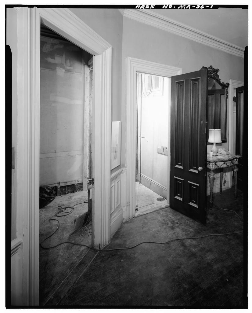
1 photograph from the federal survey record, Library of Congress.
Present Use
167 words
Source document
Quoted word for word from HAER MASS,13-BOST,72-.
Not written, edited or summarised by this site.
Elevator dismantled and removed to the NMAH, January (Catalog/Accession No. where presently it is in storage. Significance The elevator was representative of an important mechanical development in vertical transportation. According to the Smithsonian, "The rope-geared hydraulic elevator was introduced to the United States about and quickly superceded the steam elevator with its numerous economic and functional disadvantages...With improvements by many inventors and manufacturers, the rope-geared elevator by about was the mainstay of the industry, in a variety of configurations.
By the end of its useful life, about displaced by the direct-plunger hydraulic and the electric, it was the system of choice for the largest installations in terms of lifting capacity, rise, speed, and smoothness of operation. It is, in fact, the rope-geared hydraulic elevator that is 'the elevator1 so commonly cited as being at the least co-equal with the iron/steel skeleton frame in having made the skyscraper possible. The Marlborough Street installation incorporates every important feature of the system in its basic configuration and system of control..."
Written history
4514 words
The headings the report itself prints. Each one jumps to where it begins.
Source document
Quoted word for word from HAER MASS,13-BOST,72-.
Not written, edited or summarised by this site.
Robert M. Vogel, Curator, Division of Mechanical & Civil Engineering National Museum of American History Smithsonian Institution 72 Marlborough Street: Residential Hydraulic Elevator (Wheeler-Donelan House: Hydraulic Elevator) HAER Wo. MA-56 (Page 2)
History
The house was built in and the elevator installed about based on the styling of the car and the fact that the type was not introduced until about The elevator may have been installed to serve an invalid, in view of the short run, although an article in Haj^jir^s_J4onthly_ observes that plunger-type hydraulic elevators were then being "put into the houses of wealthy residents of the Back Bay region in Boston" in great numbers. According to Matthias B. Donelan, MD, the third owner of the house since the elevator operated until when it was reported that it "jammed" or "froze." Because of the war, it was not repaired. The car reposes about two feet above the 3econd floor level, confirming that its service life came to an end as the result of mechanical failure rather than conscious decision.
Dr. Donelan is now remodeling parts of the house and wishes to remove the elevator to gain the space. The builder of the elevator, the Elias Brewer & Company of Boston, is not indicated on any visible parts of the car or machinery, but may come to light during research into the city's permit records (which might also reveal the installation date). As there were a considerable number of Boston elevator manufacturers at that time it seems likely that the installation is by one of them. II.
Description
The elevator is of the Armstrong or rope-geared water-hydraulic type with horizontal "pushing-type" cylinder. Its energy was drawn from pressure of the city water mains that drove it. The water did not circulate within the system, but was discharged into the house waste line and then the sewer, at each cycle, on the car's descent. The power to raise the car and its load was provided by a piston being pushed out of the cylinder by the water under pressure. To the piston rod is attached a set of four movable or traveling sheaves which, with a set of four fixed sheaves at the opposite end of the cylinder, form a tackle in reverse. As the piston was forced out of the cylinder, the two sets of sheaves were separated, drawing in the free end of a wire rope reeved between them.
This end passes up the side of the hoistway, over the sheave at its top, and down to the car. Thus, as the rope was drawn in, the car rose. But as the tackle ratio or "gear" is the car traveled eight times farther and faster than the piston. The cylinder length had to be only 1/8 the run of the car, but conversely the piston had to exert eight times the force needed to raise the car (plus a bit more for friction. In descent, the weight of the car overhauled the 72 Marlborough Street: Residential Hydraulic Elevator (Wheeler-Donelson House: Hydraulic Elevator) HAER No. MA-56 (Page 3) tackle and forced the piston back into the cylinder, the water within discharging into the sewer.
The raise, hold, and lower movements were controlled by an operating or control valve adjacent to the cylinder, worked by a hand rope from the car or shaft doors. a. Details Car. The car is about feet deep x 2 feet wide with capacity for one person seated or two standing up with the seat folded up. The sides and back are solid oak-paneled- The floor is transverse boards and the ceiling is a diamond-pattern wire grill set in a molded frame separated from the sides and end by turned spindles. The car gate is the standard sliding lazy-tongs type and appears to be a later addition. An electric ceiling light with switch on the car's south wall clearly is a modification.
A gas pipe above the car ceiling and a gas cock on the south shaftway wall at the second floor level testify to the original means of lighting the car the connection between the car and the supply line at the cock having been by way of a flexible rubber gas line. Fitted within the car, the wood car yoke or crosshead is a conventional Otis-type, broken-rope, wagon-spring safety. Its dogs are arranged to engage the wooden guide rails. The car is of the "corner-post" type, the guides set on diagonally-opposite corners of the hoistway (northwest and southeast). Hydraulic (power) Cylinder. The hydraulic cylinder is located in the basement machine room, directly below the shaft and offset to the north.
Made of cast iron, the north or back end is closed by a cast-iron head bolted to a flange on the cylinder. The other end is open and the piston rod is attached to the traveling-sheave crosshead by a single set screw. The system pushes to the south and the crosshead is carried on a pair of circular-section rails by two small rollers, the inner (east) one being larger than the other. This cants the sheaves slightly, so that the ropes in passing back and forth between the traveling and fixed sheaves feed into the sheave grooves straight. The cylinder is 4 feet, 1/2 inch between faces, the piston about inches thick. This gives a stroke of about feet (x8 = the two-story rise of about 28 feet). The cylinder bore is 16 inches.
With the city main's pressure (assumed) of 40 psi, the piston would have exerted a push of pounds / 8 (the gear) equals a pound pull on the hoisting rope x .75 for friction loss to equal a 750 pound net pull. The counterweight weighs about 72 Marlborough Street: Residential Hydraulic Elevator (Wheeler-Eonelan House: Hydraulic Elevator HAER Ho. MA-56 (Page 4) 250 pounds, in effect adding that amount to the effective lift which then is about pounds. The loaded car would weigh about pounds, leaving a fair margin of power. The hoisting rope (wire rope) passes up the hoistway along the south wall at its east corner. Control valve. The operating or control valve is just west of the cylinder end (north).
It is of conventional design, working vertically in the valve chamber and moved by a rack engaging a small pinion on the operating-wheel shaft. There are three positions: UP (main pressure behind the piston, STOP or REST (all ports closed, the car held against the solid body of water trapped in the cylinder), and DOWN (water from the mains shut off and water discharged from the cylinder). The valve positions are the reverse of this: UP (car rising), with the valve piston at the bottom of its stroke, and vice versa. The valve is moved by a continuous wire-rope control or operating rope that passes around the valve sheave and a small sheave at the top of the hoistway. The two sides of the loop passes through the northwest corner of the car.
The elevator was operated by pulling on either part of the loop, either from the car or one of the hoistway doors (to bring the car). The car was automatically stopped at the top and bottom of its travel by stop buttons on the operating rope engaged by the car ceiling and floor. These would return the valve to the stop position at either extreme. There was no danger of bottom overtravel, for the car would simply land on the hoistway floor its normal bottom position. A top overtravel device is fitted supplemental to the operating-rope stop button. This consists of a rod alongside the traveling-sheave crosshead, on the outer end of which is a lug. This was engaged by a striker bar on the crosshead if it moved beyond its normal outer limit.
This caused the rod to move with the crosshead, drawing in a chain of which the one end was attached to the handle of a quick-opening (or closing, in this case) valve in the supply line below the operating valve. This operation shuts off the water supply to the cylinder and the car will come to a stop before being pulled into the hoistway ceiling. When the valve was returned to the down position, the cylinder water was discharged, the car would descend, and the quick-opening valve would be opened by a weight acting opposite to the action of the limit device. 72 Marlborough Street: Residential Hydraulic Elevator (Wheeler-Donelan House: Hydraulic Elevator HAER No. MA-56 (Page 5) Metering.
A dial counter "behind the valve on the north wall of the machine room appears to have "been cobbled up from a gas-meter register. This must have been operated at one time by a small line or wire from either the operating-valve wheel or the crosshead, to provide a rough accounting of the volume of water consumed by the elevator for billing, as the amount would have been far too great to be passed through the house water meter. Counterweight. Part of the car's dead weight was balanced by a cast-iron counterweight operating in wood guides on the east hoistway wall. The counterweight rope is missing, the weight blocked about three feet above the floor by a wood strut. Plumbing. The elevator supply is by way of a 3-inch iron line from the main in Marlborough Street.
A stop valve almost wholly buried in earth below the front steps served to isolate the system and presumably is where the water is stopped when the elevator was taken from service (whether it was disconnected from the main then or later is not known). The supply line runs from the north foundation wall southeast to the quick-opening valve, with the line and valve being in a crawl space below the basement. The discharge from the operating valve is through a "syphon-relief" loop adjacent to the valve. This prevented the cylinder water from draining out if the car were somehow arrested in its descent, which then would allow the car to drop freely when the obstruction was removed.
The loop maintained the full volume of water in the cylinder and was a standard safety device for horizontal-cylinder hydraulic elevators. From the loop, the water discharged to the house soil line which pitches to the rear (south), indicating that the sewer is in the alley rather than in the street, an uncommon arrangement. From the cylinder open end, a 1-1/2-inch line runs down to the soil line to carry away any water that seeped by the piston, keeping it off the machinery-room floor. There apparently are ports in the floor of the cylinder at its outer end into which this water would drain, but they are now completely clogged with grease and are not visible. h.
ltiJiP.B All elements of the system are in remarkably good order, considering that it has been out of operation for some 42 years. The car is in near perfect condition, with a good finish and no excessive varnishing of the panelling. The operating valve moves 72 Marlborough Street: Residential Hydraulic Elevator (Wheeler-Donelan House: Hydraulic Elevator) HAER Wo. MA-56 (Page 6) freely and there is no rust. The piston is unquestionably jammed in the cylinder the weight of this pound car was bearing on it for 42 years and this seems to be the only appreciable mechanical defect in the system. All castings are sound and free of cracks or chips, and all hearings essentially free of wear. The three-inch, quick-opening valve is frozen with rust, but probably can be freed will no ill effects. c.
General Remarks A more ideal representative of this important development in vertical transportation in a museum setting could not be imagined. The rope-geared hydraulic elevator was introduced to the United States in and quickly superceded the steam elevator with its numerous economic and functional disadvantages, the principle one of which was that because of the necessary winding drum, it was severely limited in the length of rise it could serve. With improvements by many inventors and manufacturers, by the rope-geared elevator was the mainstay of the industry in a variety of configurations.
By the end of its useful life in it was the system of choice for the largest installations in terms of lifting capacity, rise, speed, and smoothness of operation, but it was displaced by the direct-plunger hydraulic and the electric. The system also found a number of industrial uses, such as blast furnace charging and wharf cranage. In fact, it is the rope-geared hydraulic that is so commonly cited as being "the elevator" the least co-equal with the iron and steel skeleton frame that made the skyscraper possible. The Marlborough Street installation incorporates every important feature of the system in its basic configuration and system of control, but at a diminutive scale that makes its ultimate museum display entire feasible.
Poatscript The Donelan House elevator has been collected by the Smithsonian Institution (catalog/accession No. It was moved from its site on January For additional details on the elevator itself and its installation in the house, see the attached Report on Dismantling the Residential Hydraulic Elevator at the Matthaig B. Pqnelan House, January 23, 72 Marlborough Street, Residential Hydraulic Elevator (Wheeler-Conelan House, Hydraulic Elevator HAER No. MA-56 (Page 7) REPORT ON DISMANTLING THE RESIDENTIAL HYDRAULIC ELEVATOR at the MATTHIAS B. DONELAN HOUSE 72 MARLBOROUGH HOUSE, BOSTON WITH OBSERVATIONS ON THE ELEVATOR'S INSTALLATION January National Museum of American History Catalog/Accession No.
The work was carried out as a lump-sum contract by Manitou Machine Works of Cold Spring, New York, specialists in the removal, rigging, and erection of antiquarian machinery. The contract price, was based on inspection of the elevator by MMW proprietor, Tom Rick, about 10 days earlier. The MMW crew consisted of Rick, his son, Seth, and Harold Murphy, self-employed carpenter and mechanic who does work for Dr. Donelan. His knowledge of the house was of considerable help in the course of the job. Work began at a.m. Saturday, January 19* Mr.
Murphy had already removed all built-in shelving and cabinet work in the basement machine room that housed the hydraulic cylinder and control valves (all shelving and cabinets were original and were built around and wholly enclosing the elevator machinery, following its installation ca. The work was conducted in the following sequence: 1. To relieve tension on the hoisting cable for removal of the cylinder, the car was slightly raised and left suspended from a chain hoist hung from a web sling passed around the bottom rims of the main and counterweight sheaves at the hoistway top.
The hoist chain was attached to the car by another sling passed under the car yoke (with the hoist cable detached from the car, the safety should have engaged and its dogs gripped the guide rails, but when the car was lowered a foot or so by the hoist, the safety did not operate, its joints apparently frozen from disuse). It was also noted that the considerable subsidence of the fourth floor bathroom floor beneath the two top sheaves was due to the fact that the car part of the counterweight rope was directly in line with a joist that had been drilled through for the rope with a 1-1/4-inch hole. With most of its substance removed, the joist located in this critical spot failed, throwing much of the load of the car and counterweight (by way of their sheaves) to the adjacent joists.
As the sheave 72 Marlborough Street, Residential Hydraulic Elevator (Wheeler-Donelan House, Hydraulic Elevator HAER No. MA-56 (Page 8) pedestals were lag-screwed directly to the finish floor, it is unclear that the floor framing had not been exposed from above during the installation. And, if the hole had been located from below (presumably by plumbing down the shaft from the hoistway ceiling), and the existing plaster ceiling of the former closet had not been disturbed, the joists had not been accessible from below either.
The elevator installers, encountering a joist just where a hole was needed, apparently drilled through it and hope that enough of the joiat was left to hold without splice plates or that the system as a whole would carry the load (perhaps pounds highly concentrated) by transference, as it did, but with the noted subsidence. That the floor system held at all under such stress again testifies to the inherent robustness and forgiving character of light timber-frame construction, particularly that of the century. The car was not lowered to the first floor at this time because the floor had just been refinished and stained, and furniture had been stored in the shaftway. 2.
The control rope was detached from its sheave on the control valve, and the four control-rope guide pulleys at the machine-room ceiling were removed and the rope parts moved a3ide. 3. The control-valve cap was unbolted, the control sheave, shaft and pinion were removed, and the cap replaced, 4. The finish (rough) and sub-floors were removed from the west half of the machine room to give easy access to the crawl-space piping rather than by way of the floor trap in the kitchen. 5. The siphon-relief loop was cut by torch from the waste line below the floor and the flange between it; the discharge line at the bottom of the control valve was unbolted, and the loop lifted out and removed.
(The siphon relief prevented the draining of any water from the cylinder if the car was arrested during descent, so as to prevent its sudden drop when the obstruction was removed.) 6. The manifold casting that connected the top and bottom of the control valve with the connection to the cylinder was unbolted at its three flanges and removed. The cylinder and control valve were now entirely free of one another. 7. A small hole was drilled in the three-inch supply line below the floor to determine whether, by any remote chance, it still was under the pressure of the mains. Though thought to be it did spurt water under very low pressure. This was simple water that remained in the 72 Marlborough Street, Residential Hydraulic Elevator (Wheeler-Donelan House, Hydraulic Elevator) HAER No.
MA-56 (Page 9) line between the valve under the front entrance of the house, where it had stopped (presumably at the time the system jammed and was taken from service about and the quick-opening valve beneath the control valve. It soon ran out. 8. Next, the hoisting cable was attended to. Because both the fixed end of the cylinder and the free end at the car were fitted with ainced-on sockets, at least one of these would have to be either unzinced or the cable would have to be cut in order to pull it through various small-bore holes, rope guides, etc. At that point, because of the further difficulty of pulling one part of the rope through the first-floor area where it might whip and cause damage, it was determined to sacrifice the entire rope.
In any case, it would have been replaced when the elevator was reinstalled in the museum. The rope was torch-cut in several places in order to free the cylinder, while the free end up from the machine room to other top sheave was left for removal later. 9. The flange between the control valve and its supply pipe below the floor was unbolted and the valve, now free of all attachments, was removed. The various small pullies and the counterweight to hold open the quick-opening valve of the top-overtravel stop system was removed from the crawl space. 10. The traveling sheaves were separated from the crosshead and pushed back along the guide rails, the crosshead was separated from the piston rod, and the crosshead was removed.
This gave clearance to pull out the sheaves, as a group, on their shaft. 11. The two crosshead guide rails were unbolted from the cylinder flange and their near ends dropped to the floor. 12. This permitted the entire cylinder to be slid southward, lifted slightly by a come-along hung from the two beams that had supported the control-rope sheaves. That provided enough clearance between the cylinder head-end and the machine room north wall to remove the fixed- sheave assemble from its carrier arms on the cylinder head. 13. The cylinder was slid back (northward), providing clearance to remove the guide rails and their (far) end support. 14.
At this point, an attempt was made to prise the cylinder head off the cylinder casting, but the gasket, most likely the original, seemed to provide a perfect bond and it would not budge. From fear of cracking the cylinder flange, it was left on and rebolted to the cylinder. The 72 Marlborough Street, Residential Hydraulic Elevator (Wheeler-Donelan House, Hydraulic Elevator) HAER No. MA-56 (Page 10) cylinder, cylinder head (with fixed-sheave arms), piston and piston rod were left as a unit (there is no doubt that it was the piston jamming in the cylinder that had caused the elevator to "freeze up" in as reported by the lore of the house.
This was bit simply a matter of a charge of water becoming trapped in the cylinder, for all hydraulic passages, large and small, were entirely free* An attempt was made to move the piston back into the cylinder, but with no success. It remains baffling as to how a piston could so completely jam in a smooth cylinder. There is no scoring of the cylinder wall, at least in the visible open end of the cylinder. The answer will be revealed when the cylinder head is removed at the museum, presumably by hydraulic pressure which will either push the head off or the piston out). 15. The cylinder (unit) was slightly lifted and its two support feet were removed.
It is interesting to note that neither of these, nor that carrying the far ends of the crosshead guide rails, were fastened to the floor in any way, nor were the foot castings attached to the cylinder. The constant longitudinal thrust of the cylinder (southward, away from the valve end), due to the pull of the hoisting rope, was resisted solely by the x 3-1/2-inch horizontal bolster against which the top of the cylinder's open end bore. This and the pipe connection between the cylinder head and the control valve were the only points of connection between the cylinder/guide rail assembly and the building (other than the three feet), allowing the system's organs to adjust freely to slight movement without restraint and resulting stress. 16.
The cylinder, with the help of the come-along, was tilted and rotated, so that the head-end was down, allowing the residual water to drain out. The cylinder then was turned and moved out of the machine room. Once in the hallway, it was moved on rollers to the back door and out. The fixed-sheave arms and projecting piston rod, although increasing the weight, were of enormous help in the manhandling of this fairly heavy and awkward piece/ 17. The supply line was torch-cut just before the quick-opening valve, and the valve and its section of line to the control valve were removed from below the floor. 18. The open ends of the supply and waste lines were stopped off with plumber's expanding test plugs.
The l-l/2-inch line from the cylinder open end (to drain seepage past the piston) was not stopped off, having a swing check valve before its connection with the house waste line. 72 Marlborough Street, Residential Hydraulic Elevator (Wheeler-Donelan House, Hydraulic Elevator) HAER No. MA-56 (Page 11) 19. The control rope was cut at several points (as it was frayed in various places, it was not saved), the fittings cut off and salvaged, and the upper sheave (in a recess in the hoistway ceiling) removed. This completed the removal of the elevator's mechanical organs on January and No work was done on January On Tuesday, January 22, the Ricks and Murphy lowered the car to rest on the first floor and tilted it out into the parlor through the (recent) opening at the north side of the hoistway.
They found that it was light and small enough to be removed from the house and transported intact without dismantling, except for some minor decorative bits. Finally, the counterweight, the upper hoisting and counterweight sheaves, and sample sections of the car and counterweight guide rails were removed, the machinery and car were loaded on the Manitou truck, and all was prepared for the trip to the museum. (ROTE: The major steps of the removal operation were photographed, as was the entire system before removal.
Refer to National Museum of American History and Historic American Engineering Record 5x7-inch photographs, and field measured drawings for details of the installation and its extirpation.) A major disappointment was the failure to discover the slightest mark revealing the identity of the elevator's maker, as the previously hidden parts of the car and machinery were exposed. There remains hope that in time documentary research will bring this to light. Further observation uncovered the lack of quality workmanship in certain aspects of the installation that might be regarded as critical. The cutting or removal of joists without provision for replacement members has been noted.
Then, the attachment of the car guide-rails was surprisingly casual, the work being done entirely with nails and with little attempt at securing to studs or other framing. In removal, the sections came away from the walls with almost no effort. It might be said that, as the sections bore upon one another down to their final bearing on the first floor, and that as the car was hung from the hoist cable on center, and thus there would have been little lateral load on the guides, this should have been adequate. But what if the cable had ever failed and the safety had engaged to arrest the car (as it presumably would have done earlier when it was in good order)?
As the safety had gripped the guides and thus thrown the entire weight of the car onto them, it can be imagined that under those circumstances, the guide sections would buckle and car, rails and all would have crashed to the first floor. This is all in surprising contrast to the general high level of workmanship of the elevator itself, both car and machinery, and even of some elements of the installation. The support of the control cable pulleys and the cabinet work 72 Marlborough Street, Residential Hydraulic Elevator (Wheeler-DoneIan Hou3e, Hydraulic Elevator) HAER No. MA-56 (Page 12) boxing in the equipment in the machine room were beautifully done. Tom Rick poses the interesting question, "Was an unskilled crew sent out? ...
or was the contract taken too cheaply, leading to corner-cutting?" He surmises the former, for even if money were to be lost, an experienced crew would realize that the indiscriminate cutting of structural members might very well be adding to their problems. A related query is whether the installers were the elevator's manufacturer's own field crew, or a general contractor employing carpenters and plumbers, or some combination of these, or something entirely different? ftimwi&i M* i/fttgac ,WTIOU nu WMSTWAY V^WO^J F^ T_ CTIQAJ ^ jfef^^ ff. LDOtCfMQ
The original filed report, and the sheets the survey produced. Those published here appear above.
Also surveyed in Boston
24 of 217 records shown
The federal surveyors worked through Boston building by building. These are the other structures
they measured and filed a report on, longest report first.
 Block
Block