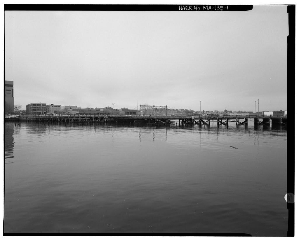
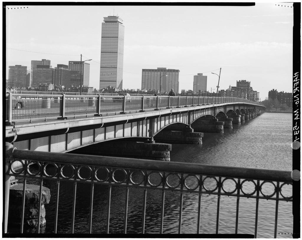
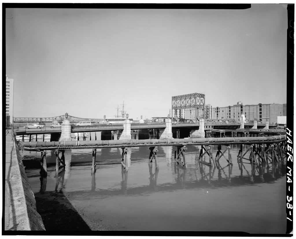
The Summer Street Bridge (over Reserved Channel) is the older of two known retractile drawbridges surviving in Massachusetts, and one of only four known to survive in the United States. The Summer Street Bridge is an advanced example of an unusual bridge type which eventually gave way to simpler, less expensive types of movable bridges in the twentieth century. Proiect Information: This documentation was initiated as a mitigation measure during the Federally funded replacement of the Summer Street Bridge by the Massachusetts Highway Department.
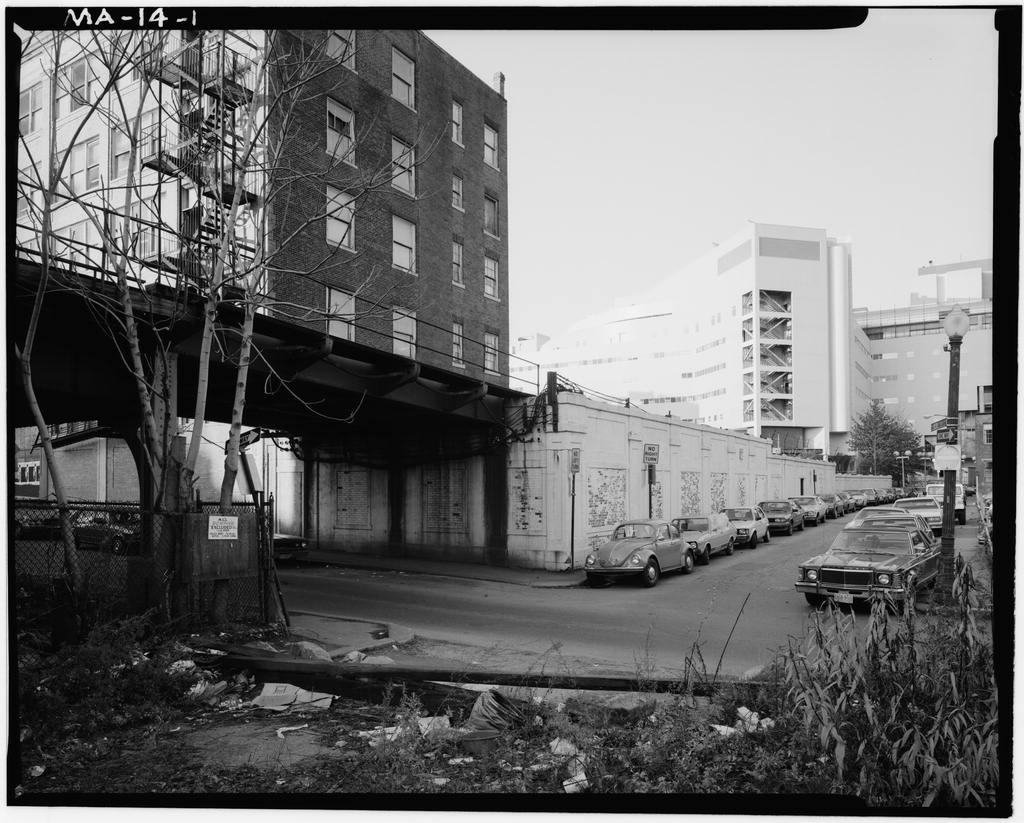
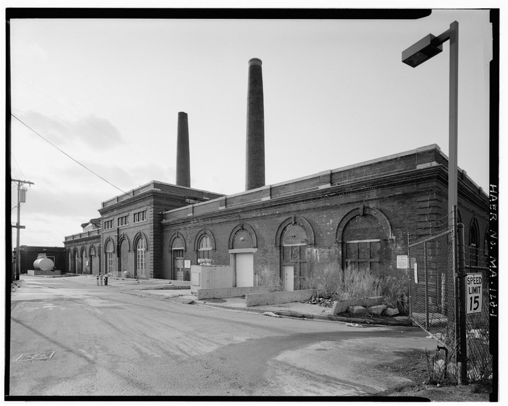
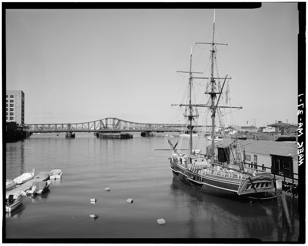
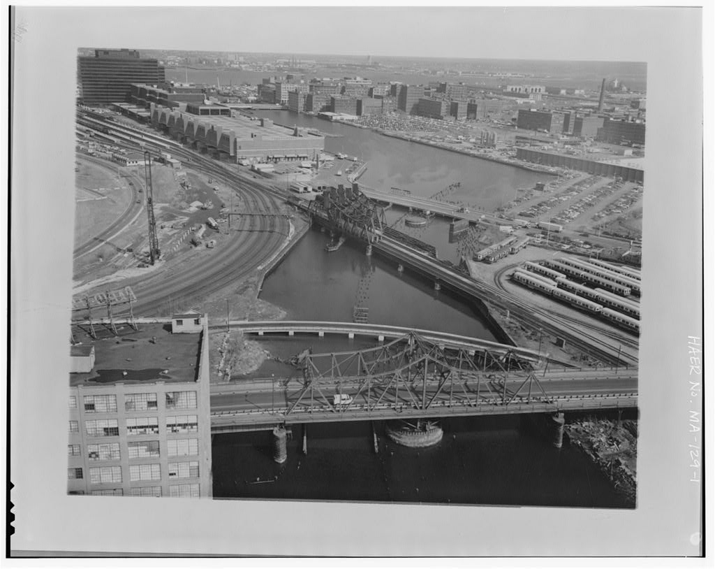
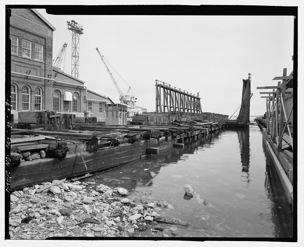
This documentation was prepared between December and August by: Lola Bennett, Historian McGinley Hart & Associates Architects and Planners 77 North Washington Street Boston, Massachusetts Martin Stupich, Photographer 25 Mayhew Street Dorchester, Massachusetts SUMMER STREET BRIDGE (L Street Bridge) HAERNo.MA-135 (Page 2) Site Description The Summer Street Bridge1 spans the Reserved Channel on the northern side of South Boston, approximately one-quarter mile west of the mouth of Boston's Inner Harbor. The Reserved Channel area is dominated by large-scale industrial warehouses, the former U.S. Naval Reservation/Boston Army Supply Base on the northeast, and the Boston Edison L Street Power Station on the southeast.
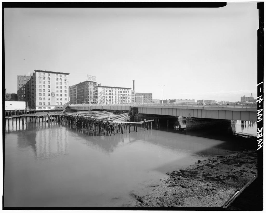
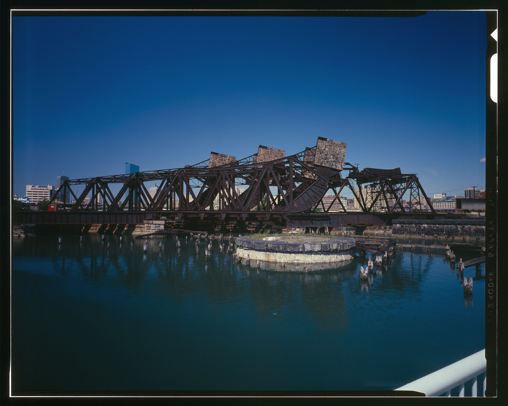
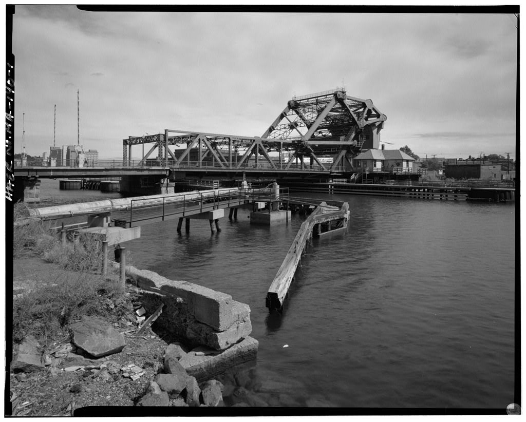
Bridge Description The 932-foot long Summer Street Bridge is comprised of a single-leaf, double-barreled, oblique retractile drawspan, and 55 much later approach spans. There are 42 approach spans (totaling approximately north of the draw and 13 approach spans (totaling approximately south of the draw. The drawspan is trapezoidal in plan, measuring long on its eastern side, long on its western side, and 70' wide throughout. The drawspan opened by retracting obliquely to the northeast, clearing a 40-foot-wide channel. The drawspan is comprised of three lines of built-up, riveted wrought-iron half-through plate girders (each comprised of a web plate and flanges with a series of riveted cover plates), with two girders in each line.
The girders in the central line are each deep; the girders in the two outer lines are only deep. The three southern (or channel-span) girders each measure long; each is pin-connected at its northerly end to the cantilevered end of its anchor-span counterpart. The anchor-span girders vary in length from 100*-7i " (eastern), through iff' (central), to (western). A built-up, 25-foot high mast or "Samson post"2 is mounted directly above the southerly bearing of each anchor-span girder, and is rigidly attached to the girder's web. Each Samson post is comprised of two channels, connected with lattice and top and bottom tie plates. Two pairs of eyebar stays are pinned to the head of each mast by means of a diameter pin.
The upper halves of these stays are variably sized to diameter) round rods; these are mated by turnbuckles to variably sized to flat eyebar lower halves. The lower ends of the stays are pinned to the webs of the associated channel-span and anchor-span girders. The three Samson posts are laterally braced by built-up, latticed portal struts; a pair of builder's plates are centered on the portal strut over the westerly barrel. The entire drawspan superstructure is mounted on three double-truck and four single-truck carriages (the easternmost double-truck carriage is currently missing.) The trucks are of the railroad-style, bogie type. Each is attached to the superstructure by means of a vertical king pin, which allows each truck to swivel in a horizontal plane.
The single trucks are mounted 1 The earliest name for the structure, "L Street Bridge," is found on the plans and in the City Engineer's annual reports until about when the structure was renamed "Summer Street Bridge," as its official location is on Summer Street, rather than L Street. Subsequent city documents generally refer to the structure as "Summer Street Bridge (over Reserved Channel)," to distinguish it from "Summer Street Bridge (over Fort Point Channel)." Throughout this report, the bridge is referred to by its contemporary name, except in direct historical quotations which refer to it as "L Street Bridge." 2 While this structural member could also be correctly called a "mast," the term "Samson post" is found on the plans and in all subsequent MHD records.
SUMMER STREET BRIDGE (L Street Bridge) HAERNo.MA-135 (Page 3) under plate sockets built up on the soffits of the anchor-span girders. The double trucks are mounted under cast sockets bolted to the bottoms of three built-up "truck rockers." The three truck rockers are located beneath the anchor-span girders, directly below the Samson posts. Each rocker is U-shaped in section, and is pin-connected to the web of the girder which it cradles. The pin-connected rockers allow the double-truck carriages a small amount of vertical movement, contributing to a more even distribution of forces to the supporting rail system.
The carriage assemblies rest upon the remains of three sets of steel rails (a fourth set, the original easternmost, has completely disappeared) laid on a timber pile bent substructure. The truncated remains of two of the original four timber pile bent runways extend northeasterly from the bridge, and the ruins of a wooden winch house, with a motor and winch still in place, are located on a pile-supported platform beyond the ends of the runways. A steel wire cable is still wrapped around the winch's winding drum; both ends of the cable run back to, and are attached to, the drawspan superstructure (the lower end of the cable first reversing direction around a sheave mounted on the drawspan substructure).
A modern, welded steel bent has been built as an emergency support under the southerly ends of the anchor-span girders. The main floor system of the drawspan consists of transverse metal floor beams, riveted to the girder webs, carrying longitudinal rolled steel stringers and an open steel grid deck. Many of the floor beams on the western side of the draw are modern, rolled steel I-beams; most of the remaining original built-up floor beams have undergone extensive repairs. The (added) projecting sidewalks consist of timber stringers and plank decks carried on steel brackets riveted to the outer girders.
There is crossed-diagonal lateral bracing, comprised of IB" diameter rods attached to brackets riveted low on the girder webs, in each full-sized panel between girders and floor beams; in addition, there is a single, threaded-end longitudinal tie rod centered in each floor-system panel. Four built-up, latticed struts stiffen the floor frame over the double-truck rocker assemblies; other struts are used in the irregularly shaped panels at the drawspan's ends. Metal latches, bolted to the decks of the approach structures, engage the upper ends of the central girders of the drawspan when the bridge is closed.
Three cantilevered metal landing blocks, attached to the northerly end of the southern approach structure, support the toe ends of the drawspan's channel-span girders when the bridge is closed. There are two sets of gates at each end of the drawspan to control vehicular traffic. All of the gates are currently open, but Jersey barriers have closed the easterly barrel to vehicular traffic. The outer faces of both sidewalks are currently lined with modern chain-link fencing. Drawspan Operation The Summer Street Bridge's retractile mechanism was originally operated by steam power, and after by electricity. The operation was controlled from the tender's house, located on the westerly side of the drawspan.
A separate machinery house was originally located on the westerly side of the drawspan, next to the tender's house. Following a fire in both the tender's house and machinery house were rebuilt, with the new machinery house being constructed on the northeasterly side of the drawspan at the end of the two center runways. According to notations on the plans, the then-existing electric motor and winding drum were reused, as well as some of the original cable sheaves. SUMMER STREET BRIDGE (L Street Bridge) HAERNo.MA-135 (Page 4) As operated under electric power after as a vessel approached the drawspan, the tender applied power to the winch, causing its horizontal drum to slowly rotate.
A steel wire cable, wrapped numerous times around the drum, would be wound in at the top of the rotating drum, while an equal length of cable was simultaneously unwound from the drum's bottom. The end of the cable coming onto the upper surface of the drum runs back to the drawspan superstructure, and is attached to it directly. The end of the cable coming off the drum's lower surface also runs back to the drawspan, but it passes beyond the end of the upper cable, and reverses direction by passing up and over a sheave mounted on the drawspan substructure, before attaching to the superstructure.
Operating the winch in the forward position would tighten the upper length of the cable, pulling the movable structure outward along the runways; operating the winch in reverse would tighten the lower length of cable and pull the drawspan back into its closed position. Operation of the bridge prior to would have been similar, but would have required a somewhat more complicated cable system to reach the original machinery house. Each time the draw began to open, the toe ends of the draw's three channel-span girders would slide off the [originally sloping] landing blocks mounted at the end of the southerly approach structure.
The pinned connection between the channel-span and anchor-span girders allowed the outer ends of the channel-span girders to drop until sufficient resistance was developed in the stays, Samson posts, back stays, and anchor-span girders to support the whole weight of the channel span. (Additional counterweight was originally provided by cast iron boxes rilled with lead, mounted within the anchor-span floor system.) Only when the draw was drawn closed again, and the toe ends of the channel-span girders were forced back up on the landing blocks, would the strain on the rest of the draw be relieved. South Boston History Like Boston proper, much of South Boston was built on filled land.
South Boston, originally known as "Dorchester Neck," served as a common pasture during the seventeenth and eighteenth centuries. The peninsula's pastoral character began to change when it was annexed to Boston in South Boston came to be dominated by a number of industries established during the first half of the nineteenth century, and eventually was the most heavily industrialized district of the city. As the demand for land increased, the marshy area known as The Flats stretching northward from the original two-pronged peninsula of "Dorchester Neck" was gradually rilled for development.
The Hats and the intervening South Bay became available for commercial development as a result of the efforts of three entities: the Boston Wharf Company, the Commonwealth of Massachusetts and various railroad companies. Filling proceeded eastwardly from the Fort Point Channel and had reached the northerly bounds of the present Reserved Channel by the early A large expanse of new land between these two channels was developed into rail yards and a warehouse district with an array of new waterfront piers. Summer Street was extended across this new land and became a major artery for freight wagons.
Several bridges over the Fort Point Channel allowed access into and out of downtown Boston, while the Summer Street Bridge carried a lesser volume of traffic into the old industrial section of South Boston and up L Street to the residential neighborhoods beyond. SUMMER STREET BRIDGE (L Street Bridge) HAERNo.MA-135 (Page 5) Construction of the Summer Street Bridge The construction of the Summer Street Bridge was authorized by the state Legislature in June as part of the Commonwealth's development plan for the South Boston Flats.
Chapter 388 of the Acts of entitled: "An Act to provide a Public Highway Bridge across the Reserved Channel at South Boston" reads as follows: The City of Boston is hereby authorized and required to build and maintain a Public Highway Bridge across the Reserved Channel in the South Boston flats in said city, connecting Eastern Avenue or Congress Street, so called, as laid out and graded by the Commonwealth, with L Street extended to the southerly line of said channel Said bridge shall be constructed in accordance with plans prescribed or approved by the board of harbor and land commissioners.
Upon the completion of said bridge, provided the same is completed before the first day in August in the year eighteen hundred and ninety-two, forty per cent, of the cost thereof shall be reimbursed by the Commonwealth to said city out of the Commonwealth's flats improvementfund The Summer Street Bridge was designed by the City of Boston Bridge & Ferry Division, and the movable span was fabricated by the King Bridge Company of Cleveland, Ohio. The original plans were signed by William Jackson, City Engineer The contract for the approach spans went to William L. Miller of Boston; machinery was built by Miller & Shaw of Cambridge; and the trucks were engineered and furnished by Charles Carr of Boston.
The drawspan was erected between October 18 and November 15, at a cost of The City Engineer's report described the bridge as follows: There is one draw of the retractile type, having three lines of girders, the middle line dividing the roadway into two parts. ...Each line of girders is composed of two non-continuous plate girder-spans, one of which spans the channel; the other, or rear span, being supported on trucks running on tracks built on the draw foundation. When the draw is in position for travel, the front end of the channel span rests on shoe plates on the draw landing of the main bridge, the other end being attached to and supported by the rear span by a pin connection.
When the draw is in motion or run off, the front end of the channel span is supported by suspension rods passing over Samson posts on the rear span to back end of this span, proper counter-balances of cast-iron boxes filled with lead being provided where necessary. The draw is operated by steam power; the draw and machinery for operating it were designed by this department.4 According to city documents the bridge was open only to pedestrians for over a year until the streets were completed. The Summer Street Bridge was opened to traffic on June 3 "An Act to Provide a Public Highway Bridge Across the Reserved Channel at South Boston," Acts of Massachusetts. Chapter p. 4 City of Boston, "Report of the Engineering Department for the Year (City Document No. 10, p.
5 City of Boston, "Report of the Engineering Department for the Year (City Document No. 10, p. SUMMER STREET BRIDGE (L Street Bridge) HAERNo.MA-135 (Page 6) Repairs and Alterations-Approach Spans As originally designed, the approach spans had a hard pine stringer/plank deck superstructure supported on timber pile bents. In the Boston Elevated Railway repaired and strengthened the approach spans and the drawspan for heavier loads. A fire destroyed a large section of the northerly approach in and it was rebuilt shortly thereafter.
The northerly approach was completely rebuilt a second time in the southerly approach was rebuilt in Because the approaches have been rebuilt, no significant features remain from the original construction, and they do not contribute to the historical significance of the bridge. Repairs and Alterations-Drawspan The drawspan of the Summer Street Bridge was subject only to routine maintenance and repairs until when it underwent major repairs and strengthening to allow it to carry 42-ton street cars.
The contract was awarded to Ellis on October and the work was completed September 3, at a cost of The roadway paving, sidewalks, and entire roadway flooring, most of the stringers and part of the sidewalk bulkhead andfences were renewed; 168 oak piles were driven, some to carry the street cars, others to replace those that had been eaten by the limnoria; additional stringers were furnished under the lines of car rails. The draw landing and some of the supports for the draw were built of steel, the tracks were repaired and the draw pit was replanked. Asphalt sidewalks were also laid.6 At this same time, and apparently under the same contract, the Summer Street drawspan was converted from steam to electric power.
City Engineer's reports from the indicate that both steam and electric power were being used for the city's movable bridges, although the reasons for choosing one over the other is not clear. While the report on the Summer Street Bridge only mentions, "The draw is operated by steam power," a report one year earlier on the construction of the Federal Street Bridge hints that there may have been some question about the performance of the relatively new electrical technology: The motive power for the draws is electricity, in addition to which gearing, etc., is provided for operating them by hand or horse power in case of accident to the electric plant. ...Thus far the electric power has worked satisfactorily.
7 Although steam power continued to be used for movable bridges for several decades, it rapidly became clear that electric power was far less expensive than steam power. In their reference book Movable and Long-Span Steel Bridges, engineers George A. Hool and Kinne stated: 6 City of Boston, "Report of the Public Works Department for the Year (City Document No. 26, p. 7 City of Boston, "Report of the Engineering Department for the Year (City Document No. 11, p. SUMMER STREET BRIDGE (L Street Bridge) HAERNo.MA-135 (Page 7) In the selection of mechanical power, the electric motor is given the first place, the internal combustion motor second, and steam power third....
Steam power is satisfactory as far as handling the load is concerned, but is very expensive to maintain in ready operating condition as the steam pressure must be kept up at all times. This type of power requires a boiler and steam engine and needs more attendants to operate it than in the case of electric or internal combustion motors. For a lift bridge that is operated only a comparatively few times, the steam power is very expensive. There is a further objection to the coal smoke from the fires.* By the city had eight retractile drawspans, three of which were operated by steam and five of which were operated by electricity. In the annual report for the city's Bridge Department, Superintendent of Bridges Patrick F.
McDonald discussed the expense of operating the city's movable bridges: There are fourteen important tide-water bridges maintained by the City of Boston, namely, Broadway, Chelsea [South], Congress street, L street, and Warren, operated by steam power; Atlantic avenue, Charlestown, Chelsea [North], Dorchester avenue (formerly Federal street), Dover street, Maiden, Meridan street, and Summer street, operated by electricity; and Mt. Washington avenue, operated by hand power. ...
In the interest of economy I would recommend that the power used to operate the Broadway, Chelsea [South], Congress street, L street, and Warren bridges be changed from steam to electric power or compressed air, at an estimated expense of and thus make a saving of over per year on the expense for coal.9 This statement is borne out in the classification of expenditures for that year which indicated fuel costs for the retractile bridges as follows: Steam power: Warren L Street Chelsea South Electric power: Federal Street Maiden Summer Street Dover Street The conversion to electric power did not occur for several years, apparently due to a major restructuring of the department which occurred between and From until the city's bridges were under the jurisdiction of the City Engineering Department.
In the city had an official Bridge Department, but by the City Engineering Department and the Street Department had been reorganized as the Department of Public 8 George A. Hool and Kinne, Movable and Long-Span Steel Bridges (New York: McGraw-Hill Book Company, p. 9 City of Boston, "Report of the Bridge Department for the Year (City Document No. 7, pp. SUMMER STREET BRIDGE (L Street Bridge) HAERNo.MA-135 (Page 8) Works. Under the old system, the City Engineer was required to make inspections and report on the safety of the city's bridges as well as supervise repairs, while maintenance responsibilities rested with the Superintendent of Streets.
The result of this arrangement was that although the City Engineer repeatedly recommended repairs on bridges he had no authority to put his recommen- dations in force. His recommendations were frequently ignored and bridges...were allowed to suffer through neglect... "10 Thus, it was only after the establishment of the Public Works Department in that the Summer Street Bridge was rebuilt. The next reconstruction of the bridge followed a major fire in which destroyed a large section of the pile approaches and a small section of the drawspan. The bridge was reconstructed at a cost of The drawspan and approaches were widened to accommodate a street-widening project on the South Boston side.
The sidewalks, which were originally located inside the girders, were replaced by the present cantilevered sidewalks at this time, and the original three-pipe iron guardrail mounted atop the outer girders was removed. A new draw tender's house was built, together with an operating house, by Coleman Brothers, Inc., under a contract approved October 8, and completed December at a cost of Other documented repairs and alterations to the Summer Street Bridge are summarized in the following list: Drawspan foundation repaired following storm damage. Navigation lights added. Ellis & Son Co.
repaired the piers and fender guards, replaced old piles, renewed old timbers and replaced the floor; draw landings were repaired, stringers, caps and planking of the pier and fender guards were renewed where necessary. Piling and timbers supporting the retractile rails replaced at a cost of Repairs to drawspan and landings. Timber underdecking & surface planking removed and replaced by open steel-grid deck on drawspan. Southerly approach spans replaced. Northerly approach spans replaced. Draw foundation rebuilt. Tender's house destroyed by fire. 10 City of Boston, "Report of the Public Works Department for the Year (City Document No. 29, p.
4.) SUMMER STREET BRIDGE (L Street Bridge) HAERNo.MA-135 (Page 9) Emergency repairs following partial collapse of timber substructure due to a runaway barge; repairs allowed westerly side to be reopened to traffic. Movable Bridges Movable spans are required where bridges crossing navigable streams cannot economically be built high enough to provide proper clearance for passing vessels. The more popular types of movable bridges are: swing bridges which pivot on a central pier; bascule bridges which are raised or lowered at one end; and vertical lift bridges which are raised and lowered between vertical towers. Retractile bridges, also called traversing, sliding, or pull-back bridges move horizontally, with the span or spans pulled away from the navigation channel on rails.
Because of the excessive amount of space required to move sliding retractile bridges, as well as the expense of construction, operation and maintenance, the retractile technology never really caught on, and this type of movable bridge soon became obsolete. In his treatise on movable bridges in Bridge Engineering J.A.L. Waddell refers to this type of bridge as a "pull-back draw" and states that it was "a very unusual type" because it was expensive to build and operate.11 The Summer Street Bridge represents the culmination of the evolution of a unusual and ill-fated bridge type which eventually gave way to simpler, less expensive types of movable bridges in the twentieth century.
Retractile Bridge Technology and Operation The retractile drawbridge is known to have been used as early as the fourteenth century in Italy and southern France, where timber spans were moved longitudinally on a series of rollers.12 The modern retractile draw, featuring a movable span carried by metal trucks with wheels riding on rails, is thought to have originated in the Boston area in when engineer Luther Drew and City Engineer James13 Slade designed the original Federal Street Bridge over Fort Point Channel as a "slide draw." This earliest Boston retractile had Samson posts supporting turnbuckle-adjusted stays and pulled away from the channel at a diagonal.
Thomas Pratt inventor of the Pratt truss, is believed to have played a major role in the development of the retractile bridge type, as his service with the City Engineering Department coincides with the earliest known retractile spans in Boston, In while Pratt was serving as Assistant City Engineer to N. Henry Crafts, he patented an improvement to the trucks of the retractile draw mechanism, "whereby the weight of the 1movable platform of such bridges may be more nearly equalized on the wheels and bearings." * [See copy of patent in appendix.] That same year, the second and third retractile drawspans in Boston were constructed. One year later, when Pratt left the City Engineer's office, his position as Assistant City Engineer was filled by John E. Cheney "who appears to have 1[ J.A.L.
Waddell, Bridge Engineering. 2 vols. (New York: John Wiley & Sons, 12 Stephen J. Roper, "Movable Bridges Under Purview: An Overview," (Boston: Massachusetts Department of Public Works, June 13 Frederic C. Detwiller, McGinley Hart & Associates, "HAER No. MA-41: Summer Street Retractile Bridge," 14 T. Willis Pratt, "U.S. Patent Improvement to Draw-Bridges," February 22, SUMMER STREET BRIDGE (L Street Bridge) HAERNo.MA-135 (Page 10) adopted the retractile draw enthusiastically."^ Cheney's period of work in the City Engineering Department approximately coincides with the city's construction of retractile bridges.
By the city had built ten retractile drawbridges: Charles River Bridge over Charles River, Maiden Bridge over Mystic River, Chelsea Bridge over Mystic River, Dover Street Bridge over Fort Point Channel, Warren Bridge over Charles River, Federal Street over Fort Point Channel, and Summer Street Bridge over Reserved Channel, Summer Street Bridge over Fort Point Channel, By the end of this period, the retractile bridge in Boston had evolved from a horse-powered, rack-and-pinion-driven, combination timber/iron structure, to a cable-driven, steel structure powered first by steam and later by electricity. Of the ten known retractiles built in Boston, only two remain: the Summer Street Bridge over the Fort Point Channel and the Summer Street Bridge over the Reserved Channel.
Apparently, the only other U.S. city to make use of the retractile design was New York, where a total of five retractile spans, constructed between and are known to have been under the control of the City's Department of Bridges in Other retractile draws were built on the Erie Canal towpath, but the type is not thought to have been common in any other area of the United States.17 The King Bridge Company The King Iron Bridge & Manufacturing Company (name simplified to King Bridge Company around of Cleveland, Ohio, was one of the leading manufacturers of metal truss bridges in the United States during the nineteenth century.
The firm was established in by Zenas King, who, like many of his engineering counterparts, had no formal training and learned his profession through practical experience. While in Cincinnati during the King was employed as an agent of the Moseley Iron Bridge Company which specialized in a unique "tubular wrought iron arch bridge" patented in Under the proprietorship of Thomas Moseley, the firm relocated to Boston about the time of the Civil War, but King remained in Ohio. Within a year, King and an associate, Peter Frees, had developed their own tubular wrought-iron bowstring bridge and established a bridge and boiler works in Cleveland. The King Bridge Company was a prolific nineteenth century bridge fabricator and is best known for its manufacture of iron truss bridges.
One undated advertisement for the company advertised ''Highway, Swing &. Railroad Bridges, Iron Turntables &, Machinery of All Kinds."19 King went on to develop his company into one of the largest iron bridge- 15 Peter Stott, undated, unpublished typescript in Historic Bridge Inventory file Massachusetts Highway Department, Cultural Resources Section. 16 City of New York. Department of Bridges. Annual Report. Year Ending December 31. 17 Stephen J. Roper, "Notes on Retractile Bridges," in Historic Bridge Inventory file Massachusetts Highway Department, Cultural Resources Section. 18 Victor C. Darnell, Directory of American Bridge Buildiny Companies.
Occasional Publication SUMMER STREET BRIDGE (L Street Bridge) HAERNo.MA-135 (Page 11) building operations in late-nineteenth century America.19 According to industrial historian David Simmons, the company's success was based upon several factors: King's close links with the iron and steel industry of northeast Ohio and an extensive use of labor-saving devices and standardization in the manufacturing process provided a competitive advantage that made possible the erection of bridges whose numbers and geographic distribution were paralleled by few other American bridge-building companies.20 Although much of the company's success was due to its concentration on a single type of bridge, the bowstring arch, the King Iron Bridge Company "fabricated and erected many types of structural metalwork," including King's patented tubular swing bridges.
Significance The Summer Street Bridge (over Reserved Channel) is an extremely rare, if considerably altered, example of a highly unusual movable bridge type the retractile draw. The retractile bridge type appears to have been primarily developed in Boston in the second half of the nineteenth century, where it reached its peak in the steel-framed, electrically powered, cable- driven Summer Street Bridge (over Fort Point Channel), constructed in (HAER No. MA-41). The slightly earlier Summer Street Bridge (over Reserved Channel) falls just short of this apogee, in its use of wrought iron rather than steel for its draw superstructure, and in its use of steam (originally) rather than electricity as its power.
The retractile bridge type was abandoned in the early twentieth century in favor of simpler and more economical types of movable bridges, primarily bascules. Today, there are only four known surviving retractile bridges in the United States: the two Summer Street bridges in Boston (the one over Fort Point Channel is currently under reconstruction); and two in New York City-the Carroll Street Bridge in Brooklyn, and the Borden Avenue Bridge in Queens.
In Massachusetts, the Summer Street Bridge (over Reserved Channel) is the third- oldest of the eight known nineteenth-century movable bridges still surviving in the Massachusetts Highway Department's bridge database, and is one of just five known bridges in the database built by the King Bridge Company of Cleveland, Ohio, a prolific nineteenth- century bridge fabricator known for its successful use of labor-saving devices and standardized manufacturing processes. No. 4 (Washington, DC: Society for Industrial Archeology, 19 David Simmons, "Bridges and Boilers: Americans Discover the Wrought-Iron Tubular Bowstring Bridge," The Journal of the Society for Industrial Archeology, vol. 19, no.
2 20 Simmons, "Bridge Building on a National Scale: The King Iron Bridge and Manufacturing Company," The Journal of the Society for Industrial Archenlnpv. vol. 15, no. 2 SUMMER STREET BRIDGE (L Street Bridge) HAERNo.MA-135 (Page 12) Sources Engineering Drawings City of Boston Engineering Department, "Draw for L Street Bridge, July eight sheets. [City of Boston Public Works Department files.] Bibliography Boston Redevelopment Authority. "The Bridges Over and Thru the Fort Point Channel," unpublished manuscript. Boston, City of Boston. "Engineering Department Annual Reports," "Public Works Department Annual Reports," Condit,CarlW. American Building Art: the Nineteenth Century. New York: Oxford University Press, Darnell, Victor C. Directory of American Bridge Building Companies.
Occasional Publication No. 4. Washington, DC: Society for Industrial Archeology, Detwiller, Frederic C, McGinley Hart & Associates. "HAERNo. MA-41: Summer Street Retractile Bridge," Hool, George A. and Kinne. Movable and Long-Span Steel Bridges, 2nd edition. New York: McGraw-Hill Book Company, Merriman & Jacoby. A Textbook of Roofs and Bridges. 3rd edition, Roper, Stephen J. Massachusetts Department of Public Works [now Massachusetts Highway Department] Historic Bridge Inventory, Bridge No. May-October Simmons, David. "Bridge Building on a National Scale: The King Iron Bridge and Manufacturing Company," The Journal of the Society for Industrial Archeology vol. 15, no. 2 pp. Simmons, David. "The King Iron Bridge & Manufacturing Co.," Society for Industrial Archeology Newsletter.
Bridges Special Issue, vol. 8, numbers 1 and 2 (January & March Stott, Peter. "Bridge Row: The Bridges of Fort Point Channel," unpublished typescript. Boston, June Stott, Peter. SIA [Society for Industrial Archeology] Boston Conference, "Friday Morning Tour Notes." SUMMER STREET BRIDGE (L Street Bridge) HAERNo.MA-135 (Page 13) Pratt, Thomas W. "U.S. Patent No. February Waddell, J.A.L. Bridge Engineering. 2 vols. New York: John Wiley & Sons, Works Progress Administration. "Official Project No. Report on Summer Street Bridge over Reserved Channel," City of Boston, Department of Public Works, Bridge & Ferry Division, SUMMER STREET BRIDGE (L Street Bridge) HAERNo.MA-135 (Page 14) _ . NORTH Location Map (USGS Boston South, Mass.,
 Block
Block