Demolition of South Station Tower 1 is to be funded by the Federal Railroad Administration (FRA) as part of the Northeast Corridor Improvement Project. Under Section 106 of the National Historic Preservation Act of mitigative documentation was undertaken by the FRA by historians Janice G. Artemel and E. Gallagher in May South Station Tower 1 and Interlocking System (Northeast Corridor Project) HAER No. MA-58 (Page 2) For many years after its opening on January 1, South Station in Boston, Massachusetts, was America's largest and busiest railroad station. The station plans included many progressive features, including an interlocking system designed to serve over 700 trains a day and capable of handling the simultaneous movement of 11 trains entering or leaving the station.
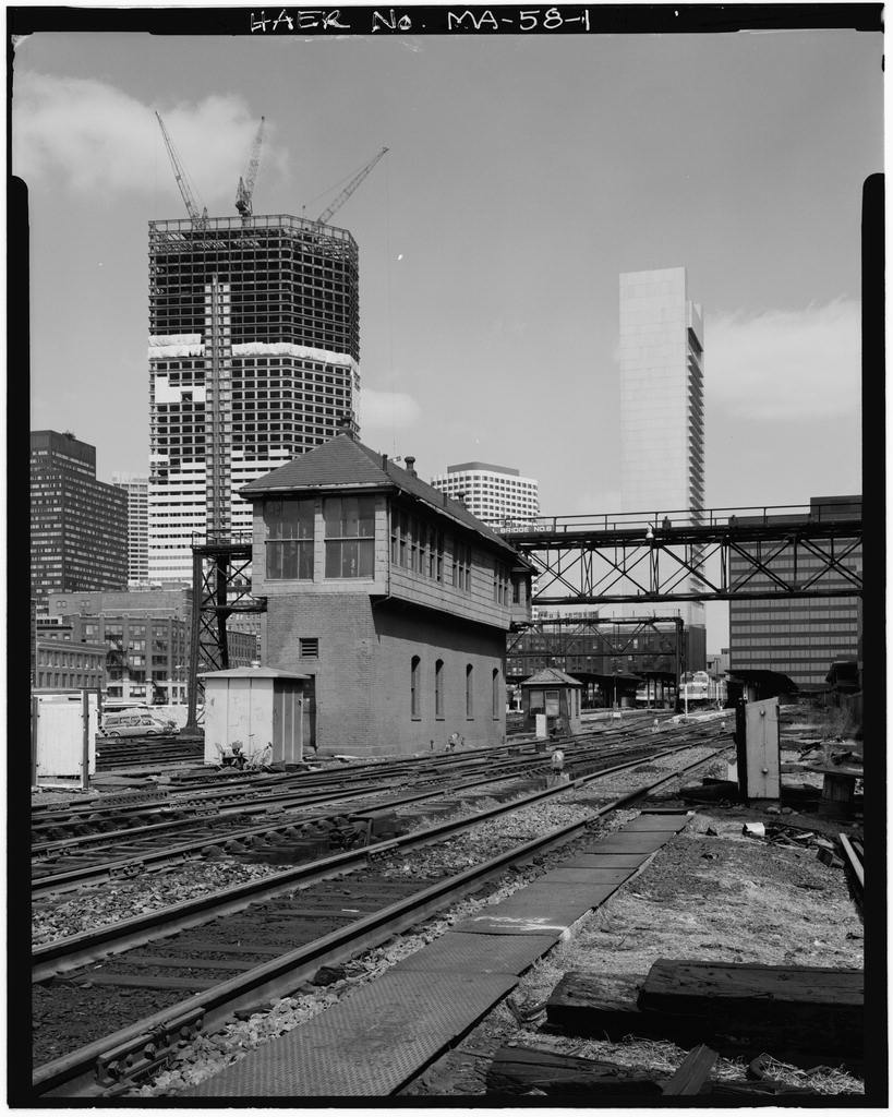
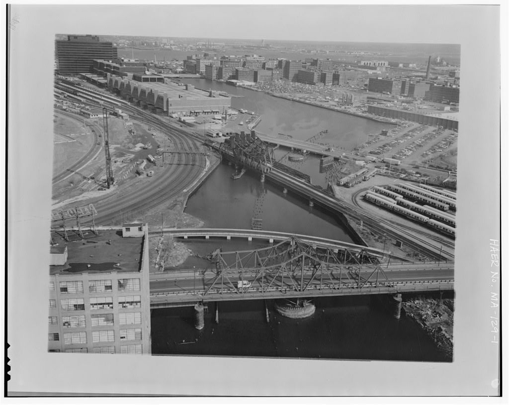
The Westinghouse electro-pneumatic interlocking plant installed at South Station was a complex system of semaphore signals, steel truss signal bridges, switches, and frogs controlled from three interlocking towers, two of which have been demolished. The remaining main tower, known as Tower 1, houses a 143-lever, electro-pneumatic interlocking machine that was put into use on May 6, South Station and its interlocking plan are located on the southeastern edge of Boston's central business district (Figure l). The station is at Dewey Station at the intersection of Atlantic Avenue and Summer Street (Figure 2). The site is bounded on the east by the Stone and Webster Corporation Building, the U. S.
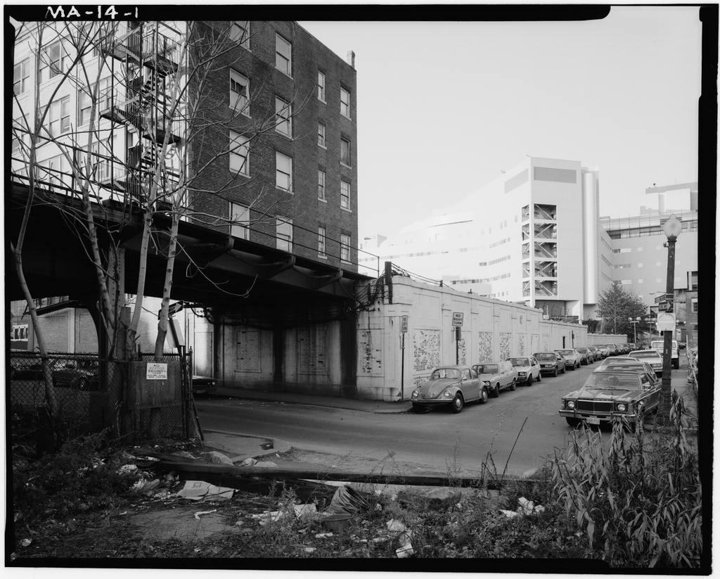
South Postal Annex, and the Fort Point Channel, and on the west by Atlantic Avenue and the Massachusetts Turnpike ramps. Tower 1 is located approximately feet southwest of the station. Officially declared to be a blighted area of the city in the and designated as a redevelopment district, the South Station area is currently undergoing major new construction. Historic Background of Interlockings An awareness of the principles and historical development of interlockings is instrumental in understanding the function and significance of South Station interlocking system and tower.
An interlocking is an arrangement of railroad switches and signals interconnected so that one movement must succeed another in a predetermined manner.^ An interlocking is required when tracks interconnect and prevents conflicting routes from being set up when trains are switched from one track to another. In an interlocking, the switch moves a section of track and the signal indicates what is happening. Switches and signals are operated from a central location by levers. The levers are grouped together in a common frame, and the assemblage is called an interlocking machine. Generally, the machine is housed near the tracks in a two or three-story structure known as an interlocking tower.
Because the switches, signals and other operating devices are interlocked, the operator in the tower is prevented from human errors in throwing the switches or displaying the signals. Interlocking originated in England, with the first mechanical interlocking invented by John Saxby in Saxby's "preliminary latch locking" system became widely popular, and by there were interlocking levers in use on a single British line.2 The first interlocking machine in the United South Station Tower 1 and Interlocking System (Northeast Corridor Project) HAER No. MA-58 (Page 3) States was installed in in Trenton Mew Jersey, on the Camden and Amboy Division of the Pennsylvania Railroad.5 Saxby & Farmer of London, England, furnished the material and supervised the machine installation.
S&F dominated the early market in American interlockng plants and the two mechanical machine models most frequently used in the United States were S&F machines. In the early mechanical systems, the manually-operated levers were connected to the switches with pipe and to the signals with wire, hut later, because wire stretched, both switches and signals were connected to levers by pipes.4 Within two decades of the first U. S. installation of mechanical interlockings, the mechanical machines were outmoded technologically by powered machines. Powered interlockings needed fewer operators than mechanical interlockings, which saved labor costs.
The first powered interlocking was pneumatic followed quickly by the hydraulic the hydro-pneumatic the electro-pneumatic and the electro-mechanical The all-relay system was developed in the and has, in turn, been superseded by remote, computerized, centralised traffic control. Some of the earlier systems are still in use, however. The electro-pneumatic interlocking machine was invented by the Union Switch & Signal Company (US&S), founded by George Westinghouse in The company first developed a mechanically-interlocked pneumatic/hydraulic system for operating track switches. Track movements and switches were electrically indicated with lights on a track model mounted above the machine.
In this way, the machine operator couldsee the exact status of all switches and signals in this interlocking. Soon afterwards, the US&S eliminated the hydraulic step and created an electro-pneumatic machine. This machine soon became favored by the railroads because of its reliability, durability, compactness, and ease of operation. By the electro-pneumatic machine was used in 90 percent of power-operated terminal track system.5 The electro-pneumatic machine has many advantages over its mechanical counterpart. In a mechanical machine, one lever is connected by piping to one switch; the movement of the lever is transmitted to the switch through the movement of the pipe. However, in an electro-pneumatic machine, one lever can operate many signals and switches.
When a lever of an electro-pneumatic machine is moved, an electrical circuit is completed. Electricity, by charging an electromagnet, opens a slide valve on a double-acting cylinder at the appropriate switch and compressed air moves the switch. Three wires connect the lever contacts to three electromagnets on the valve. To operate more than one switch from the same lever, the same three wires are extended to other movements with the valves connected in multiple. Thus, the electro-pneumatic equipment can handle many more switches with fewer levers.6 South Station Tower 1 and Interlocking System (Northeast Corridor Project) HAER No.
MA-58 (Page 4) The electro-pneumatic type is also more compact than a mechanical machine because the levers, not functioning as true levers as in a mechanical machine, are smaller and closer together. Generally, the levers of a mechanical machine are five centimeters apart, while the levers of an electro-pneumatic machine require only one-half of that space.7 The electro-pneumatic is also more easily operated, since it does not require the physical exertion that is necessary to operate the man-sized levers of the mechanical machine. The electro-pneumatic machine, according to US&S, also has advantages over the electric machine, including its durability.
When several switches move in an electric machine, the electricity performs a great deal of work in a short time and there is abnormal resistance to the operation of motors and solenoids which causes "destructive arcs" and overloaded conductors.^ However, in an electro-pneumatic interlocking machine, compressed air moves the switches, while electricity merely opens and closes the valves. The air is compressed to pounds persquare inch (psi). The main air pipe extends throughout the interlocking and is two inches in diameter. Branch pipes begin with a diameter and taper to at the switch.? Electricity operates the compressor(s) as well as the valves that control the compressed air, locks, indicators, and relays.
A large 20the century station usually had its own power plant and auxiliary equipment. The auxiliary equipment might be as simple as a motor generator and a bank of storage batteries. However, at some stations a delay of fifteen to twenty seconds would be an intolerable interruption, in which case auxiliary equipment might include a continuously-operator motor generator. Ten to sixteen volts (direct current) was sufficient power for most interlocking plants.-*-0 In the earlier electro-pneumatic interlockings, semaphore signals and switches were operated pneumatically. A main air line might extend over considerable track mileage and the automatic block signals between interlockings were operated pneumatically from this main air line.
After signals were electrified, there was no need for long air lines. The trend began for each interlocking to have its own compressor plant, with several sets of small compressors in instrument cases supplying the air for groups of switches, rather than all force coming from the main plant. This reduced friction loss in the main line. Efficient operation of the large passenger terminals built in the late 19the and early 20the century depended to a great extent on the interlocking plants installed. Plant failures could result in lengthy suspensions in service, accidents, substantial economic losses, and thousands of angry patrons. Safe, dependable, and rapid operation of the interlocking plant was thus a key factor in the design and operation of these terminals.
South Station Tower 1 and Interlocking System (Northeast Corridor Project) HAER No. MA-58 (Page 5) Historical Background - South Station Tower I and Interlocking System At the time Boston was settled, the South Station area was a muddy, unoccupied tidal flat off the original Boston shoreline. Population increases after the American Revolution led to extensive land filling in the cove area and significant alteration of the shoreline.
The advent of the railroad led to further changes, as the South Cove Associates, organized to provide the Boston and Worchester Railroad (later the Boston and Albany) with a terminus and yard space, began a large-scale construction project in After purchasing 75 acres of mud flats east of Front Street and bringing fill from gravel pits in Eoxbury and Dorchester by boat and from Brighton by rail, they reclaimed 55 acres of land from tidewaters, provided three miles of new streets, and built a railroad station. The Panic of curtailed additional plans for the South Cove Associations; however, much of the land south of the Old Windmill Point was filled, numerous new wharves were constructed, and the area became characterized by railroad uses.
By the Boston had become the first railroad center in the United States, and the South Cove area was traversed by the Old Colony Railroad, Boston and Albany Railroad, and the Boston and New York Central Railroad (later the New York and New England), The latter constructed a railroad station at the end of Summer Street in With the arrival of the railroad and filling of the cove, the South Cove residential areas gave way to commercial uses. This conversion was further accelerated by the Great Fire of which destroyed the New England station as well as residences north of the cove area. Shortly after the fire, another train station was built on the same site, and the dry goods, leather, and wood districts were created in the South Cove area.
During this period, South Cove had an unsavory reputation, characterized by narrow streets and dark alleys south of Essex and Summer Streets and deteriorated buildings. South Cove remained a degenerating commercial and wharf area until the when C. P. Clark, President of the New York, New Haven & Hartford Railroad Company met with Boston's mayor with an idea of using the New England station site for a consolidated terminal to serve all the railroads that entered South Boston. According to a later account by President Clark, in the after gaining control of the New England Railroad, had begun to look over the New England station to see where improvements could be made.3-3- They decided that the best approach would be a cooperative plan for a southern union terminal.
Mayor Josiah Quincy also wanted a new station, and "uttered some forceful words" in his inaugural address in January on the pressing need for a southern union station to complement the new union station on the north side of the city.12 South Station Tower 1 and Interlocking System (Northeast Corridor Project) HAEE No. MA-58 (Page 6) In June of the Boston Terminal Company was incorporated, consisting of the Boston and Albany Railroad Company, the New England Railroad Company, the Boston and Providence Railroad Corporation, the Old Colony Railroad Company, and the with President Clark as chairman. All these railroads except the Boston and Albany had "become subsidiaries of the Fi,NH<&H, which thus had controlling interest in the venture.
The Summer Street site of the existing New England station was selected for the new station because it appeared that this site could be enlarged at less cost than alternative sites would require, and it was nearer to the heart of the city.13 The other three stations for the railroads entering the south side were beyond a half-mile radius from city hall.1* It was announced that the intended to make the new station the best, as well as the largest, railroad station in the world.^ The plans drawn up for the station included the use of 35 acres of land and filling the dock areas to expand the site; removal of existing roads; demolition of about 210 structures; and construction of a sea wall along Fort Point Channel at the edge of the filled area.
The station was designed to accommodate the new motive powers of electricity and compressed air, with a double-deck plan that separated long-distance and suburban traffic, and an innovative loop track that was intended to expedite suburban trains. The elaborate track layout had eight throat tracks fanning out to 28 station tracks on the main level, plus two underground loop tracks for a total of 15 miles in length of track (Figure ?) Construction of the new South Terminal Station began in January and two years later, the first train steamed out of the station. Among the many distinctive features incorporated into the station plan was the interlocking system devised to handle the enormous amount of traffic anticipated at the station.
By the end of the first year of operation, 737 daily trains used the station. By the station handled over 38 million passengers annually, which was 16 million more than Grand Central Station in New York. In addition to scheduled trains, deadhead equipment movements at the end-of-the-line terminal (equipment turning, servicing, cleaning, etc.) brought the total number of daily train movements through the interlocking to about About two-thirds of the trains using the station were suburban trains, including 90 regular trains between and Because of the high level of activity, a large interlocking plant was required. The Westinghouse electro-pneumatic interlocking system was selected for use at the station, after consideration of both mechanical and electro-pneumatic plants.
The mechanical system would have entailed a 160-foot long interlocking tower, 360 levers, a large area of valuable land for the lead-out piping (45 feet in width in both directions from the tower), many men to operate the plan, high costs, and difficulties in laying rigid foundations for the pipe lines over the new fill.1? The recently-invented electro-pneumatic South Station Tower 1 and Interlocking System (Northeast Corridor Project) HAER No. MA-58 (Page 7) system was therefore the logical choice. It required only one-third the number of levers as the mechanical machine would have, fewer men and a much smaller tower, which conserved space and allowed Tower 1 to be located in the middle of the tracks with the best view of the switches and signals.
Plans were drawn up by US&S of Swissville, Pennsylvania, which manufactured, the interlocking machine. All switches and frogs were made by the Ramapo Iron Works. The system was installed under the supervision of J. P. Coleman of USfiS and George B. Frances, Boston Terminal Company Resident Engineer for the South Station project. When the station opened, an interim interlocking machine located in a temporary cabin near Tower 1 was used while the station yard and signal work was completed.
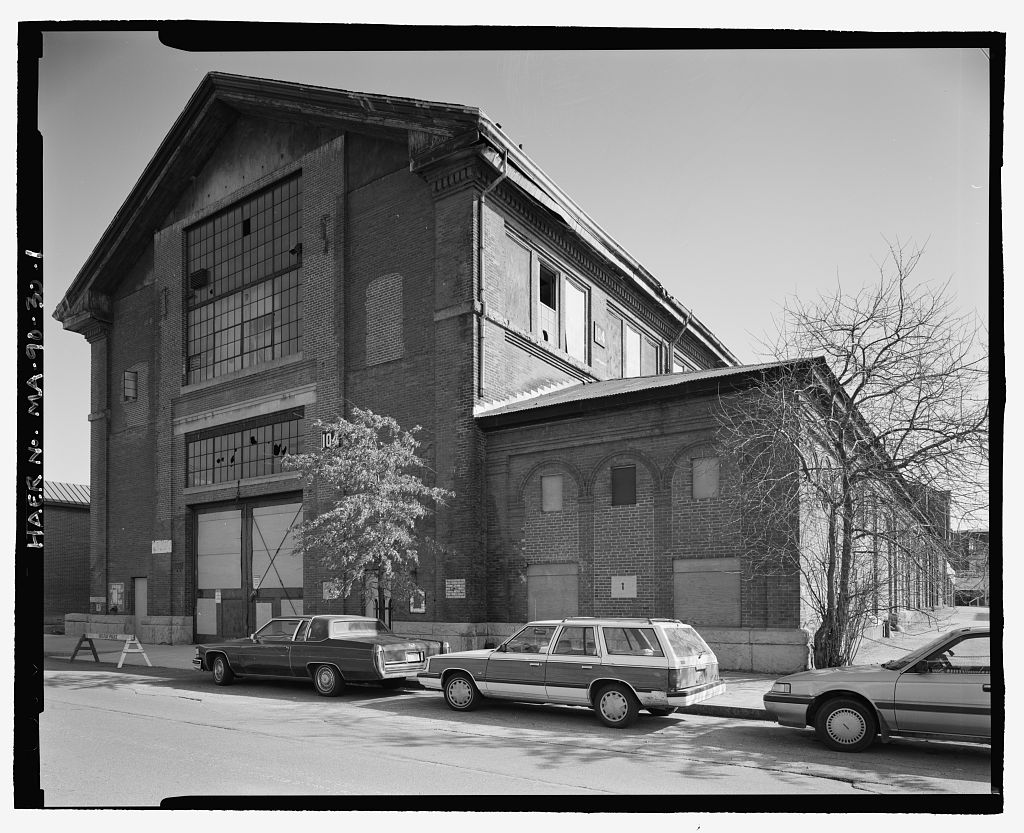
Tower 1 and its model 14 electro-pneumatic machine were put into use on May 7f The tower is a three-story brick structure with a slate roof, set parallel to the tracks (Photos 1, 2, 3 and 4) On the first floor are switch relay cases (Photo 5)* ^he tower's generating system is located on the second floor (Photos 6 and 7). The third-story houses the interlocking machine (Photos 8, 9, 10 and The third level is encircled by windows allowing a clear view of the track approaches.
The machine's 143 levers, of which 130 were used and 13 were spares, originally operated 91 high home signals, 36 cautionary signals, 21 dwarf signals, 51 double slip switches, 31 movable frogs, and 40 single turnouts, or a total of 148 signals and the equivalent of 233 single switches.-1- The levers that control switches are painted blue, the signal levers are red, and spare levers are white. Above the machine is a model board (Photo 12) operated by miniature mechanical linkages, which are mounted on the rear of the board and driven from connections to the switch levers.
There are miniature working semaphores at the top of the model board (Photo Thus, a leverman could move a lever, changing the position of the semaphore blade (arm), see the actual semaphore in the yard change position, and then see the arm of the model semaphore move to reflect the new position. At the north end (head) of the tower are other indicators which show signal positions (Photo In addition to the main tower, a smaller tower (Tower 2) was built to control switches and signals on the suburban tracks, with an 11-lever electro- pneumatic machine operating eight dwarf signals, four double slip switches, four pairs of movable frogs, and four single turnouts, or the equivalent of eight signals and 28 single switches.
A third, more distant tower (Tower 3) controlled train movements at the yard limits too remote to be controlled from Tower 1. The machine in Tower 3 also had 11 levers. The signals were generally placed on the nine steel truss signal bridges in the station yard (Photos 15, 16, 17 and These bridges varied in span South Station Tower 1 and Interlocking System (Northeast Corridor Project) HAER No. MA-58 (Page 8) from 50 to 120 feet. 19 The semaphore posts were hollow iron columns with the operating connections inside the posts, and were placed over the center of the track regulated by the signal. The semaphore blades and lights adopted were in accordance with the system of the (railroad signaling was not all standardized).
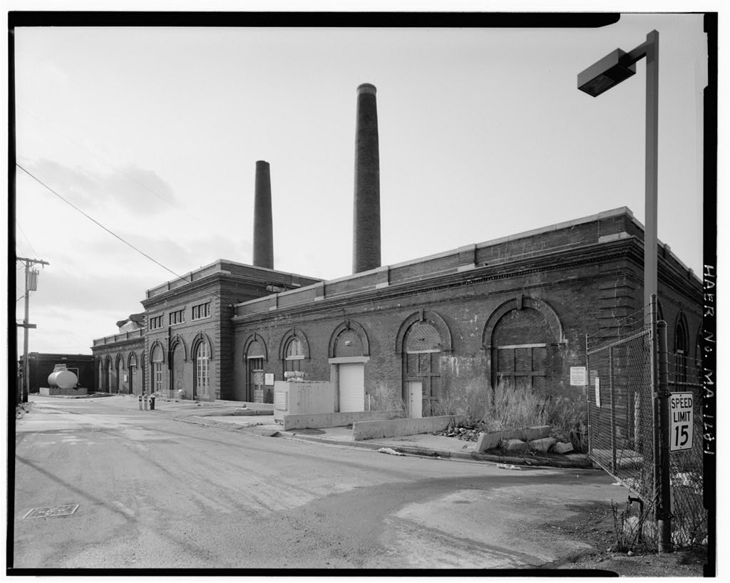
The had recently pioneered the signaling color system of red for stop, yellow for caution, and green for proceed (replacing white for proceed), and this color code was adopted at the station. Air cylinders were used to move the signal arms and switches, with magnetic valves controlled by wires which extended to contacts of the interlocking machine. Two Ingersoll-Sargeant air compressors in the power plant on the Dorchester Avenue side of the yard supplied the compressed air for the operation, one compressor being held in reserve as a relay to the other.
The air mains were duplicated, so that failure in one line of piping would not prevent immediate operation of the switches and signals through another line.20 At the beginning, oil lamps were used for the signal lights at the station except on one signal bridge, where electric lights were tried on an experimental basis. At that time, the Resident Engineer, George Francis, said that "these experiments have not progressed far enough to prove conclusively the superiority of electricity but give evidence of doing so.21 His prediction that electric lights would be adopted was soon realized; by there were 182 electric signal lamps in use.22 Hail circuits on the station tracks controlled the cautionary signals governing the approach of trains to the station and indicators within Tower 1.
A set of 28 indicators (one for each station track) were activated by the rail circuits and showed the presence or absence of trains on the station tracks. The interlocking apparatus had a provision for movements against the usual flow of traffic, although these movements were generally prohibited. Signals could be given for counter-flow movements with the consent of the director, who had a special magnetic key that cleared the signals.23 This provision allowed maximum use of the tracks while limiting the risk of collisions.
When it was built, the interlocking operation and maintenance was directed by an interlocking supervisor, who had an operating force consisting of a directing dispatcher and his assistant, a telephone attendant, a telegraph operator, and three levermen during the two-day shifts.24 At night, the operating crew consisted of a dispatcher, an operator, and two levermen. The dispatcher and his assistant issued the orders to the levermen, who were kept busy since the traffic generated about lever movements a day.25 The arrangement of tracks was such that the station could be operated as a unit, with incoming trains on one side and outgoing trains on the other, or in four sections, one for each of the main rail lines.
There was one potential South Station Tower 1 and Interlocking System (Hortheast Corridor Project) HAER No. MA-58 (Page 9) problem with the interlocking and track layout noted in by John Doerge, who was general manager of the by the time he retired in According to Droege, the elaborate track design placed too much dependence on one set of switches and crossovers.26 The track was arranged with two pairs of parallel main tracks crossing the eight throat tracks so that movement could be made from any track in the station to any of the approach tracks. These parallel tracks crossed in the shape of an "X" or double-track scissors crossing, with a slip switch with movable frogs at each point of intersection.
Droege believed that this track design was too risky, since a derailment in certain locations could tie up practically the whole interlocking plant. The subway loop conceived for electric-powered suburban trains was never operated, and these tracks were eventually torn up, although the easterly stubbed portion of two tracks was retained and used much later by the U. S. Post Office for carload mail handling. With the exception of the loop tracks, the original interlocking configuration continued with little change to the The old power plant and a gas generating plant (to supply gas for car illumination in the early years) were phased out of service and two platform tracks were discontinued.
The Boston Terminal Company came out of a bankruptcy proceeding in December and refinancing mortgage material (December included a plan of the interlocking layout as of consisting of the following track elements:27 Track Description No. of Tracks Station platform tracks Nos. 1 through 26 17 New Haven Railroad Back Bay route main tracks 4 New Haven Railroad Old Colony main tracks and leads to Dover Street passenger yards 6 New York Central (successor to Boston and Albany) main tracks 2 Universal double-slip switch leads connecting all platform tracks 4 Railway Express Agency loading and support tracks 18 East Yard tracks Nos. 21 through 25 5 Power House Yard tracks Nos.
P-5 through p-6 5 Subway tracks, stub-ended 2 Transfer Yard-Union Freight Railroad interchange 6 A drastic change in the interlocking occurred when the Old Colony suburban service was discontinued effective July 1, These trains made up roughly one-half of the volume at South Station and use of the nine easterly platform tracks was terminated. Tower 2 was removed. The U. S. Post Office later acquired the eastern portion of the property to expand its facilities South Station Tower 1 and Interlocking System (Northeast Corridor Project) HAER No, MA-58 (Page 10) along Dorchester Avenue. By the interlocking configuration'consisted of the following, according to a plan of November Track Description No. o:f Tracks Station platform tracks Nos.
1 through 17 17 New Haven Railroad Back Bay route main tracks 4 New York Central (successor to Boston and Albany) main tracks 2 Dover Street passenger yard leads 4 Universal double-slip switch leads connecting all platform tracks 2 Lead to Post Office building and support tracks 1 In the early platform tracks Nos. 1 through 7 were abandoned, reducing the active platform tracks to 10. Subsequently, three of these tracks were reactivated (Photo 19) The Railway Express Agency had discontinued operations and the tracks and buildings were removed- The Post Office ceased use of rail service, and all tracks on the Post Office property were removed or inactivated and a building addition was constructed. One of the four leads to the former Dover Street yard area was removed.
As a result of changes to the interlocking configuration, only five of the original nine signal bridges are still standing, with 31 remaining semaphore signals out of the original Electro-pneumatic dwarf signals 40L and 36L located just east of Tower 1 have also been removed and replaced by new electric dwarf searchlight units for leaving signals at the ends of the station platform tracks. By only 57 of the interlocking machine's 143 levers were working, controlling 55 signals, 17 single switches, 18 double slip switches, and nine movable frogs.30 Fifty-five of the unused levers have been removed from the machine, while others have been retained as spares.
The overall appearance of the machine is similar to the original, since adaptations can be made to the interior of the machine without altering its external appearance. In addition to the original machine, a seven-lever electro-pneumatic machine built in was added in to the tower in the late when the Broadway interlocking tower (outside the station yard, 0.6 miles from Tower l) was demolished and Broadway interlocking became remotely controlled from Tower 1 (Photo There is also a small, relatively new electric model board adjacent to the original model board which is used instead of the original model board to indicate track occupancy (Photo The interlocking system now serves a total of 144 scheduled trains operated daily in and out of South Station.
This traffic includes 24 Amtrak trains and 130 commuter trains South Station Tower 1 and Interlocking System (Northeast Corridor Project) HAER No. MA-38 (Page 11) Operated by the Massachusetts Bay Transportation Authority, which owns the station and trackage. As part of the Federal Railroad Administration's Northeast Corridor Improvement Project, South Station will be rehabilitated and the interlocking will be reconfigured. The existing signal bridges, signals, and switches will be removed. Tower 1 will be demolished and its functions transferred to the station with the installation of centralised traffic control Until the CTC system is operational, the functions will be temporarily carried out from a central instrument house (CIH) located near the existing Tower 1.
The interlocking machine and model board are to be salvaged and installed in a museum as an interpretive display. Conclusion The South Station interlocking system and Tower 1 were determined to be eligible for the National Register of Historic Places in The historic significance of the interlocking system, Tower 1, and machine derives from their function as major innovative transportation facilities on the main shoreline railroad route between New York and Boston. The interlocking system and tower were important elements in the design and historical operation of South Station, which was America's largest and busiest station for many years.
South Station's interlocking system was a prototypical solution to the problem of handling the huge numbers of track and signal changes required at a large terminal. The interlocking system was developed to serve over 700 trains a day and many times that number of movements. The use of the electro-pneumatic system successfully overcame the spacial, engineering, and labor problems that a mechanical system would have created at South Station. The machine is a type of electro-pneumatic machine which is now becoming rare. Its model board is the only one known of its kind. In addition, the semaphore signals represent rare surviving operating signals of that type. South Station Tower 1 and Interlocking System (Northeast Corridor Project) HAER No.
MA-58 (Page 12) FOOTNOTES -*- American Railroad Engineering Association, American Railway Engineering Association Manual, Chicago: American Railway Engineering Association, . p. 2 John A. Droege, Passenger Terminals and Trains, New York: McGraw-Hill Book Company, reprint ed., Milwaukee: Kalmbach Publishing Company, p. 46. 3 Association of American Railroads, Communication and Signal Section, American Railway Signaling Principles and Practices, Chapter XVI, "Interlocking," New York: Association of American Railroads, p. 3 4 Association of American Railroads, Communication and Signal Section, American Railway Signaling Principles and Practices, Chapter XVII, "Mechanical and Electro-Mechanical Interlocking," New York: Association of American Railroads, p.
3- 5 Union Switch & Signal Company, Electro-pneumatic Interlocking, Swissvale, Pennsylvania: Union Switch & Signal Company, p. 15* 6 Ibid,, pp 84. 7 John Pressley Coleman, "The Boston Southern Station: Track Facilities and Interlocking," The Railroad Gazette, May 12, pp. and Association of American Railroads, Communication and Signal Section, American Railway Signaling Principles and Practices, Chapter XVIII, "Electro-pneumatic Interlocking," New York: Association of American Railroads, p. 24- 8 Union Switch & Signal Company, Electro-pneumatic, p. 65- 9 Ibid ., pp. 15 and 19; Association of American Railroads, Electro-pneumatic, p. 4 l Proege, p. 64.
11 "Secret Escaped," Boston Post, March 21, ^"Southern Union Station," Boston Daily Globe, March 17, 13"Another Union Station," Boston Evening Transcript, March 17, i^'Real Estate Transactions," Boston Herald, March 17, South Station Tower 1 and Interlocking System (Northeast Corridor Project) HAER Wo. MA-58 (Page 13) 1 5"Work Has Begun," Boston Daily Globe, June 13, l Tom Nelligan, "Boston's South Station," Passenger Train Journal, March ^George B. Francis, "The South Terminal Station, Boston, Mass.," paper published December for presentation at the American Society of Civil Engineers Annual Meeting, New York, New York, January 18, 18 Coleman, p. ^"Opening of the Boston Terminal," The Railroad Gazette, January 6, p. 4 20 Francis, p. 21 Ibid., p.
22" oston Terminal Company Statistics," May 4, Archives of the William Litant Museum of Transportation, Brookline, Massachusetts. 23coleman, p. 2 4Ibid. 25"Boston Terminal Company Statistics." 26nroege, P- ^Personal communication from Bob Besse, Massachusetts Bay Transportation Authority, South Station Project, April 20, 28lbid. 2 9personal communication from Bob Besse, Massachusetts Bay Transportation Authority, South Station Project, April 20, ?QAmtrak, Boston Division Interlocking Book, Philadelphia, Pennsylvania: Amtrak, pages unnumbered. South Station Tower 1 and Interlocking System (Northeast Corridor Project) HAER No. MA-58 (Page 14) BIBLIOGRAPHY "Another Union Station." Boston Evening Transcript, March 17, American Railway Engineering Association.
American Railway Engineering Association Manual. Chicago: American Railway Engineering Association, Association of American Railroads, Communication and Signal Section. American Railway Signaling Principles and Practices, Chapter XVII, "Mechanical and Electro-mechanical Interlocking." New York: Association of American Railroads, Association of American Railroads, Communication and Signal Section. American Railway Signaling Principles and Practices, Chapter XVI, "Interlocking." New York: Association of American Railroads, Association of American Railroads, Communication and Signal Section, American Railway Signaling Principles and Practices, Chapter XVIII, "Electro-pneumatic Interlocking: New York: Association of American Railroads, Besse, Bob.
Massachusetts Bay Transportation Authority, South Station Project, Boston, Massachusetts. Personal communication, April 20, Boston Division Interlocking Book. Philadelphia, PA: Amtrak, "Boston Terminal Company Statistics." Archives of the William Litant Museum of Transportation, Brookline, MA, May 4, Coleman, John Pressley. "The Boston Southern Station: Track Facilities and Interlocking." The Railroad Gazette, May 12, Droege, John A. Passenger Terminals and Trains, New York: McGraw-Hill Book Company, reprint ed., Kalmbach Publishing Company, Finch, James M. Consultant and former Vice-president of Planning and Research, New Haven Railroad. Personal communication, March 29, Francis, George B.
"The South Terminal Station, Boston, Mass." Paper published December for presentation at the American Society of Civil Engineers Annual Meeting, New York, New York, January 18, South Station Tower 1 and Interlocking System (Northeast Corridor Project) HAER No. MA-58 (Page 15) Nelligan, Tom. "Boston's South Station." Passenger Train Journal, March 35- "Opening of the Boston Terminal." The Railroad Gazette, January 6, "Real Estate Transactions." Boston Herald, March 17 "Secret Escaped. Boston Post, March 21, "Southern Union Station." Boston Daily Globe, March 17, Union Switch & Signal Company. Electro-pneumatic Interlocking.
Swissvale, PA: Union Switch & Signal Company, "Work Has Begun." Boston Daily Globe, June 13, SOUTH STATION TOWER 1 AND INTERLOCKING SYSTEM (Northeast Corridor Project) t, HAER No. MA-58 (Page ig)
Baltimore Station Scale in feet Figure 1 South Station Tower 1 REGIONAL LOCATION SOUTH STATION TOWER 1 AND INTERLOCKING . - SYSTEM (Northeast Corridor Project) Lr HAER No. MA-58 (Page 17; SCALE IN FEET !' " I 1 0 100 200 300 Figure 2 South Station Tower 1 EXISTING SITE PLAN SOUTH STATION TOWER 1 AND INTERLOCKING SYSTEM (Northeast Corridor Project) HAER No. MA-58 (Page 18) z U < 0) >-l & PH 0 m H W <y ti M trt i-i 0 3 H 4J 60- In at 4J 3S^ w .e u M PC; p o 0 t/1 N
 Block
Block