Documentation of the Marine Railway was initiated in accordance with a Memorandum of Agreement between the National Park Service, the Massachusetts Historical Commission and the Advisory Council on Historic Preservation, as a mitigation measure for the demolition of the railway. This documentation was prepared between April and August for ENSR Consulting and Engineering for submission to the U.S. Army Corps of Engineers, New England Division, prior to remedial investigations under the Defense Environmental Restoration Program. It is anticipated that demolition will follow. Documentation prepared by: McGinley Hart & Associates Architects and Preservation Planners 77 North Washington Street Boston, Massachusetts CHARLESTOWN NAVY YARD, MARINE RAILWAY HAER No. MA-90-69 (page 2)
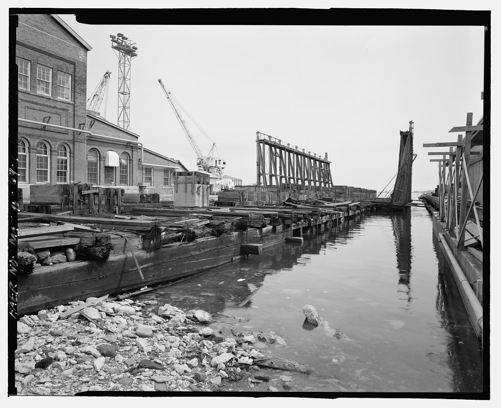
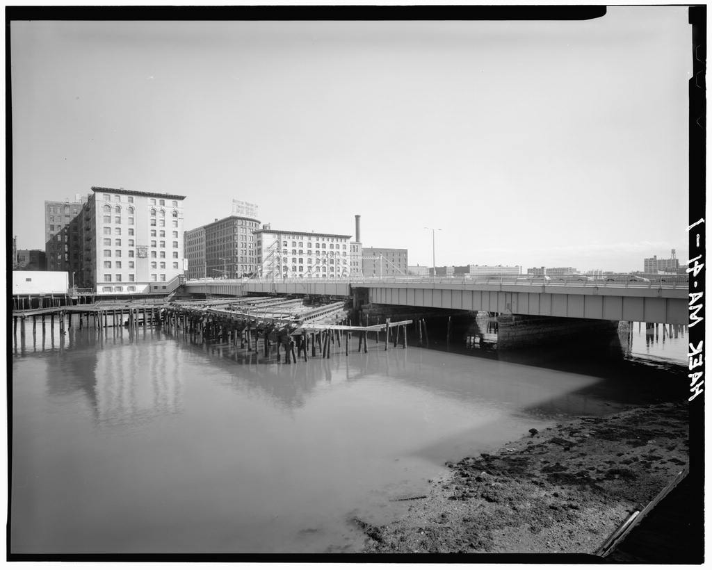
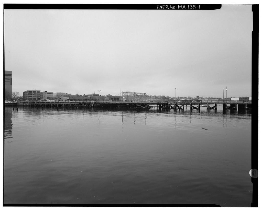
The Marine Railway is located between Piers 2 and 3 on the Charlestown waterfront, at the western end of Charlestown Navy Yard. (See location plan.) It is a large, wooden.dock-like structure, with timber cradle walls rising at right angles above the deck. The timb5!r railway platform and a substantial portion of its cradle remains and is still attached by chains to its hauling machinery on the ground floor of Building 24. The timber platform is at the same elevation as the surrounding piers, with the sides of the cradle rising above it, although the inboard walls of the cradle have been demolished for safety reasons. While much of the railway remains intact, it has suffered from severe neglect and is badly deteriorated.
MARINE RAILWAY DESCRIPTION A marine railway is a mechanical structure on an inclined track which is used for hauling small vessels out of water to expose the underside for repairs and maintenance. Essentially, it consists of an inclined railway of tracks and rollers projecting into the water, on which travels a cradle with an adjustable arrangement of bilge blocks and keel blocks for supporting the hull of the ship. The cradle is pulled out of the water along the inclined railway by means of steam-powered or electric hauling machinery, consisting of a wincling engine, a train of gears, and a series of chains connected to the underside of the railway cradle.
As originally built, the Marine Railway at Charlestown Navy Yard consisted of a wooden pile foundation, three longitudinal tracks, a wooden cradle measuring long and 52' wide,_and hauling machinery of rollers, chains, sheaves, and an electric winding engine. The railway has a total length of and maximum travel of the cradle along the track is The foundation consists of timber piles arranged in three longitudinal rows under the inclined railway. On either side, piles are in single rows spaced on center, with a few at the outer end spaced apart. In the center row, piles are arranged in transverse bents and capped with 12-inch square timbers upon which the center track is seated.
The timber tracks bear directly on the piles, and slope downward, toward the outboard end at a rate of 7/8 inch per foot, or atl;!bout a 7 percent grade, from an elevation of feet at the inshore end to an elevation of 68. 79 feet at the outboard end. There are two side tracks and one center track, the side tracks being parallel to, and 15 feet away from, the centerline. Each track is built up of three timber tiers bolted together, with a continuous steel plate rail bolted to the top. The cradle -overhangs the track on both sides and is supported by three longitudinal frames which- are in line vertically with the three tracks, and increase in height toward the outboard end.
The profile of the cradle, therefore, resembles a wedge approximating the usual trim of vessels, which thus kept the cradle and its load nearly horizontal at all times. The sides of the cradle, also known as "plank walls," are constructed of paired vertical timbers spaced at regular intervals, approximately 6' on center, and braced with paired diagonal timbers and 1" diameter rods with turnbuckles. At the upper end of these plank walls, a wooden catwalk or CHARLESTOWN NAVY YARD, MARINE RAILWAY HAER No. MA-90-69 (page 3) "docking platform" was accessible from the deck, approximately 20 feet below, by means of four wooden ladders, two at each end of the railway.
These catwalks remained above water level at all times~ so that as the railway was in operation, workers could walk along them to center the vessel and adjust the bilge and keel blocks. The cradle deck is floored with heavy pine timbers. Timber ballast boxes (or ballast lockers) under the deck planks of the cradle held stone ballast to provide negative buoyancy when the cradle was lowered into the water. Timber bilge blocks and keel blocks were fastened to beams affixed with slide irons, and could be adjusted laterally to cradle the ship's hull by means of galvanized steel chains tensioned by cast-iron hand winches arranged along the catwalks (docking platforms).
The cradle was hauled over a series of cast-iron rollers moving between the flat rail plates fastened to the lower surfaces of the cradle runners and the top of the tracks. The rollers are arranged in 15-foot-long frames which hold them rigidly in line. These frames were placed end-to-end along the length of the track. Each frame holds fifteen rollers, spaced 12" on center. The rollers measure 4" in diameter and in length for the center track, and 3- in diameter and 5" long for the side tracks. A modern roller system with bushed frames, with the same dimensions as the original roller system, was installed in The four-chain, electrically operated hauling machinery is located in the southeast comer of Building 24, and has remained virtually intact.
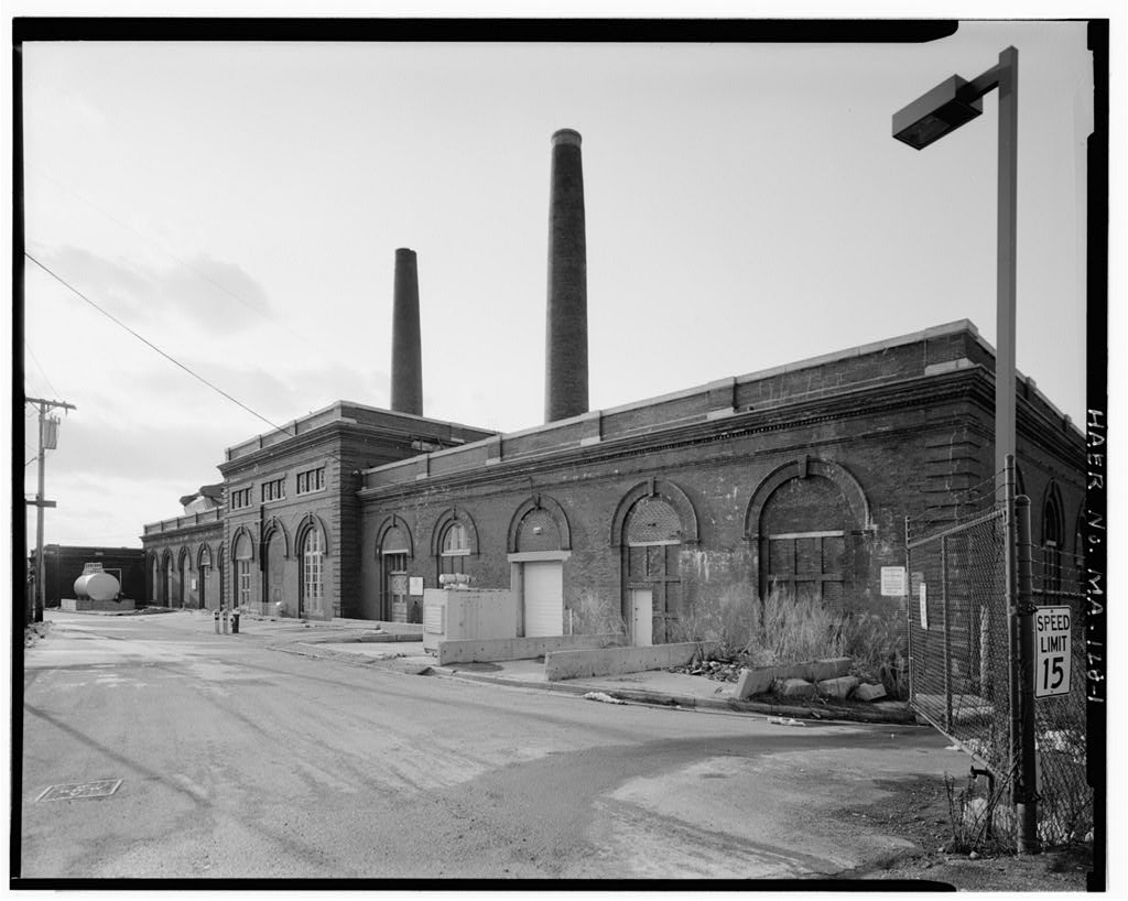
Originally, the specifications called for a one- story building to house the machinery, but apparently this was changed, as the machinery was installed in an existing building (Building The hauling machinery consists of a 200 HP, alternating current motor which drove a chain of reduction gears. The motor, manufactured by Wagner Electric Manufacturing Company of St. Louis, Missouri, was specified as: Type 31 75 BR, 3 Phase, 60 Cycles, 30 Min. Rating 55 C, 570 The gears turned a large chain wheel with pentagonal sprocket wheels on either side which engaged the links of the hauling chains. The four steel hauling chains are comprised of 2- diameter stock cast into open links measuring 14" x 7".
These replaced the original wrought iron hauling chains in The hauling chains are arranged, in conjunction with smaller open-link backing chains, in an endless system to the cradle. After passing around the pentagonal sprocket wheels on either side of the chain wheel, the chains pass through openings in the southeast wall of Building 24, and run beneath the cradle, two chains on either side of the center track. The chains are kept in line along the length of the cradle by means of cast-iron troughs attached to the transverse beams on the bottom of the cradle. The chains are attached to the cradle through a series of sheaves which function as an equalizing mechanism in order that the load on all chains is the same.
The principal function of the backing chains was to pull the lower end of the hauling chain downhill when the cradle was being hauled. The Marine Railway was built for an operating capacity of long tons. Once the size of the vessel to be hauled up was determined, the bilge and keel blocks were adjusted to fit the ship as closely as possible. The cradle was run down the railway by its own weight, and the ship floated into place above it. The cradle was then drawn up out of the water with the ship resting on the keel blocks. At a given point, the bilge blocks were adjusted under the sides of CHARLESTOWN NAVY YARD, MARINE RAILWAY HAER No. MA-90-69 (page 4) the vessel by means of a series of chains and pulleys adjusted at the level of the catwalks aboye the plank walls.
In launching, the reverse process took place. The vessel was lowered .: bymachinery to within a convenient distance of the water. The cradle was then disconnected from the links and allowed to run the rest of the way down the tracks to the water, at which point the vessel was allowed to float away. The cradle was then recovered by means of the hauling machinery. An interesting feature of the marine railway was a joint at the cradle's midpoint, which allowed the cradle to be separated into two sections so that one ship could be hauled to the inshore end of the railway, at which time the second section of the cradle could be lowered again to bring in another vessel.
EXISTING CONDITIONS Following a safety inspection conducted by Childs Engineering of Medfield, Massachusetts, in the sides of the cradle at the inboard end were demolished. Generally, many of the timber portions of the railway are loose, rotted or missing. Many of the deck planks also are broken or missing. The deck on the fantail is missing most of its planks. Many of the timber ballast boxes in the deck of the cradle are broken, and some of the ballast has fallen onto the chains and tracks. There is much loose and deteriorated material (timbers, etc.) scattered over the deck.
The structure has suffered from severe neglect since the decommissioning of the Navy Yard in and it is presently considered "in imminent danger of collapse." At the present time, the National Park Service does not have the financial resources to fund the extensive restoration that this complex structure would require in order to save it. Because it is considered a safety hazard to both pedestrians and surrounding structures, the Marine Railway is scheduled for demolition, down to the level of the tracks. Elements to be retained include the support piles, underbody, wooden track, rail plates, roller system, chains, and hauling machinery. These will be interpreted for park visitors by an historical marker.
In their most primitive form, marine railways have been used for centuries in the construction and repair of ships. Egyptians and Phoenicians used the tides to ground their ships when repairs were needed, and developed the principle of the inclined plane to haul larger ships out of water. As boats became heavier, windlasses were employed. Increasing technology brought the use of wheels or rollers to reduce friction, and later the use of steam and electricity as motive power instead of men or horses. When ships could not be hauled out of the water, a method known as "careening" was used, which involved tipping the vessel on its side in the water. Each of the early methods had its limitations, however, and usually ship repairs were greatly restricted by the ebb and flow of the tides.
Eventually, dry docks were developed, which allowed a ship to be docked and the hull exposed for repairs for as long as necessary. The major drawback to dry docking was the amount of time it took to dock and launch the vessel because of draining or filling the dry dock. CHARLESTO}VN NAVY YARD, MARINE RAILWAY HAER No. MA-90-69 (page 5) The modern marine railway, employing an inclined plane fitted with tracks and a cradle on rollers, was developed by the English in and by end of the century, marine railways were in common use. At the time of World War I, approximately ten marine railways were in use in Boston Harbor. I A small, nineteenth-century marine railway had existed at the west end of the Navy Yard before the development of Wharf No. 1.
Upon its removal, the yard had no facility for hull work on small vessels, so dry docks were used. In dry docks, the vessel was floated into place, grounded on keel blocks, the end of the dry dock was closed, and the water was pumped out. The advantage of a marine railway was the speed with which boats could be hauled out of the water. This allowed for quicker repairs and freed up the dry docks for larger vessels. Additionally, ships could be worked on at the level of the yard where there was better light and circulation, and materials and tools were more accessible. The advantages of a marine railway became clear during the World War I buildup, when the U.S. Navy acquired hundreds of patrol boats and submarine chasers, the types of small vessels for which the marine railway was designed.
In October Congress authorized construction of marine railways at naval installations at Charlestown in Boston, Newport, RI, San Diego, CA, Charleston, SC, and Pearl Harbor, HI. Crandall Engineering Company of East Boston designed and built four of the Navy's new marine railways, including the one at Boston, in
About William Hazard Crandall, who operated a shipyard at Newport, Rhode Island, constructed two marine railways which were considered so superior to previous railways that he was engaged to construct similar railways for other shipyards. In he was retained by a group of men in Boston to install a marine railway at East Boston. For this installation, Crandall engineered the first railway dry dock. 2 His innovations included higher keel blocks and a deck over the cradle which provided a working platform under the vessel, thus allowing more efficient work at all stages of the tide. Previously, men worked from the ground over and around the cradle beams which were often submerged at high tide.
Crandall also introduced docking platforms supported by upright timbers on either side of the cradle. Additionally, this railway dry dock was probably the first marine railway fo utilize steam as motive power instead of men and horses. 3 1FrederickR. Black, Charlestown Navy Yard, Historic Resources Study, Vol~me I (United States Department of the Interior, National Park Service, Boston National Historical Park, Boston, Massachusetts, p. 2J. Stuart Crandall, "Railway Dry Docks: Their Characteristics, Construction and Limitations," reprinted from The Dock and Harbour Authority, August p. 1. 3Ibid., p. 2. CHARLESTOWN NAVY YARD, MARINE RAILWAY HAER No.
MA-90-69 (page 6) At the time of construction of the marine railway at the Charlestown Navy Yard, Crandall Engineering Company was under the leadership of James L. Crandall, a third generation railway dry dock engineer. According to a company history, under Crandall's leadership, beginning in "great progress was made in engineering design and construction, installations being made in the United States, Canada, Europe and elsewhere."4 The company continued to specialize in the engineering and construction of dry docks and marine railways throughout the twentieth century. Today, the company is located in Dedham, Massachusetts, under the name Crandall Dry Dock Engineers, Inc., and continues under the leadership of the fifth generation of Crandalls.
The Marine Railway at Charlestown Navy Yard was designed by James L. Crandall, and constructed by Crandall Construction Company. Construction began in the spring of with excavation of the site, dredging, and construction of retaining walls. The foundation piles were driven during late summer. By November, work was progressing rapidly on the laying of the tracks. In January of the following year, rollers were placed and the deck was constructed. The final phase of construction, building the cradle walls and docking platforms, took place during the spring of 5 Completed in less than a year at a cost of the Marine Railway was placed in service in June On June 2, the ship USCG Ossippee was the first vessel used to test the railway.
On JunelO, the USS Grebe and USS Acushnet were hauled up in succession, to test the capacity of each half of the cradle. Each of these tests was successful, and the Marine Railway was accepted for use by the U.S. Navy.
After being tested successfully during the spring of the Marine Railway operated without incident for several years, and was in almost continuous service. During its first year of service, the Marine Railway hauled out tugboats, patrol vessels, destroyers, submarine chasers, and a floating derrick. Although the structure logged less days in service than the dry docks, it served an important function in the yard--it was a quick and economical means of hauling small vessels out of the water for repairs. During World War I, the yard serviced an average of fifty ships coming and g~ing daily, and the Marine Railway served as an efficient and economical means of qui~kly hauling vessels out of the water.
Statistics were recorded in 4Crandall Dry Dock Engineers, Inc., A Short History of Railway Dry Docks Since Their Inception in (Cambridge, Massachusetts, c. p. 1. 5Annotated historic photographs, Marine Railway Historic Photograph Collection, Boston National Historical Park Archives, Charlestown Navy Yard, Boston, Massachusetts. CHARLESTOWN NAVY YARD, MARINE RAILWAY HAER No. MA-90-69 (page 7) the Dry Dock Log. When the Marine Railway first went into service, it was designated Dock No. 3." In the structure was redesignated Dock No. 4." It wasn't until World War II that this designation was changed to "Marine Railway No. and later to "Marine Railway No. ALTERATIONS In the first accident occurred on the Marine Railway.
While hauling a boat out of the water, a link in one of the hauling chains broke. This break caused extensive damage and necessitated numerous repairs on the Marine Railway. In September Crandall Engineers conducted an underwater inspection of the track bracing. Necessary repairs were made to cradle tie rods, new wooden liners were provided for the steel frames holding the rollers, track bracing was repaired, and replacement timbers were inserted where there was extensive damage due to marine borers. That same year, the granite seawalls adjacent to the Marine Railway were replaced with reinforced concrete walls. In April additional repairs were required on the Marine Railway, following a second accident involving the hauling chains.
Under a contract awarded to the Crandall Construction Company, the original wrought iron hauling chains were entirely replaced with cast steel chains. This increased the hauling strength of the chain 36 percent. 6 The following month, alterations were made to the fantail or outboard end of the railway cradle. These changes consisted of lowering a section of the deck, replacing some of the decking with new 4-inch planks and strengthening the new work with additional diagonal bracing.7 Inspections of the Marine Railway were undertaken regularly, and repairs were made as conditions warranted. Twice, proposals were made to extend the Marine Railway, once in and again in but both times the plans were shelved.
The only large-scale reconstruction of the Marine Railway was undertaken in The side frames of the cradle were reinforced, and the cradle, track, and supporting pile structures were completely overhauled, repaired or rebuilt. , In the cradle at the inboard end of the railway was partially demolished as a safety precaution. At that time, plans and photographs were deposited in the Massachusetts State Archives in Boston as part of an agreement between the National Park Service, the Massachusetts Historical Commission and the Advisory Council on Historic Preservation. 6Crandall Dry Dock Engineers, "Report of Condition: Ton Railway Dry Dock No.
Boston Naval Shipyard, December 31, 7Crandail Dry Dock Engineers, "Alteration to Fantail," May 28, Marine Railway drawings, Boston National Historical Park Archives, Charlestown Navy Yard, Boston, Massachusetts. CHARLESTOWN NAVY YARD, MARINE RAILWAY HAER No. MA-90-69 (page 8)
Charlestown NavyYatd is nationally significant as one of the earliest naval shipyards in the United States, founded in shortly after the establishment of the U.S. Navy. Together with the navy yards af Norfolk, Virginia, and Brooklyn, New York, it was the most important facility of its kind in the United States through the end of the Civil War. Decommissioned in the yard has retained many of its historic components, and is a significant site which illustrates aspects of the naval, industrial and technological history of the United States. It is listed on the National Register of Historic Places and is a designated National Historic Landmark.
The Marine Railway is a significant ship repair structure at the Charlestown Navy Yard, and was used for nearly a half-century in the repair of small naval vessels, ranging from tugboats to submarines. It was one of several marine railways constructed at various U.S. navy yards by Crandall Construction Company during the World War I buildup. Despite recent demolition of portions of the cradle, the Marine Railway is a significant surviving example of an early twentieth-century timber railway dry dock. CHARLESTOWNNAVYYARD, ~ MARINE RAILWAY HAER No. MA-90-69 (page 9)
Bearss, Edwin C. Charlestown Navy Yard, Historic Resources Study, Volumes I and II. United States Department of the Interior, National Park Service, Boston National Historical Park, Boston, Massachusetts, Black, Frederick R. Charlestown Navy Yard, Historic Resources Study, Volumes I and II. United States Department of the Interior, National Park Service, Boston National Historical Park, Boston, Massachusetts, Brady, Mary Jane and Crandall Dry Dock Engineers, Inc. "Historic Structure Report: Marine Railway No. United States Department of the Interior, National Park Service, Crandall Dry Dock Engineers, Inc. A Short History of Railway Dry Docks Since Their Inception in Cambridge, Massachusetts, Crandall, Stuart J.
"Railway Dry Docks: Their Characteristics, Construction and Limitations," Reprinted from The Dock and Harbour Authority, August Marine Railway Architectural Drawings. Boston National Historical Park Archives, Charlestown Navy Yard, Boston, Massachusetts. Marine Railway Design Project Files, uncatalogued archival materials. Boston National Historical Park Archives, Charlestown Navy Yard, Boston, Massachusetts. Marine Railway Historic Photograph Collection. Boston National Historical Park Archives, Charlestown Navy Yard, Boston, Massachusetts. "Specification No. for Two Marine Railways at the Navy Yards, Charleston, and Boston, Mass., United States Department of the Interior, National Park Service.
National Register of Historic Places: Charlestown Navy Yard National Historic Landmark Su11ley, February United States Department of the Interior, National Park Service. National Register of Historic - Places Nomination Form: Charlestown Navy Yard, ~ CHARLESTOWN NAVY YARD, MARINE RAILWAY HAER No. MA-90-69 (page 10) I / i ! ;: . , ( .~ i ;: ~ -- I / --: I ~ c= rI - 1 ~ ~ - --- ~~ ~ s-oN 2 ' C: ! ~ \ . 1 --i ! ~ , ( . ... 1,1 l liP11: .i i 1 ... i ;,iiL: :t, . ___ ... __. 0: .. ao ~ ~ M L:~OJ~~;;:;0=~1~/--' ._,mi,,. . . ! ''( C: o -~ o t,:i ~- "~~ ~~ j '\ ~ : .; ) Is I ~ ~ 1H~ ~' [j II s:: ~ GJ I ~ ~ ..i:.,. I X - ' 1 - - f+:_i - ~ t,:i ~- -r .. c,. - .; t . I . .,J.:a;~.:.:"";: , 1 .-~ : . - ~.~ lt ... ,i ' i..:ii ~ I . . ,. . . . .-- . i ...
" , J ~~ 1 ~ ~ ~ (I.) ~ ' J1 rli~\ ~ Ji'J'./ ,r '~ ' ,, ' ~- Ill ,,. ... j, :. : :. ._;nI, .!I. .\ . , ~ o --.~o i':;, "f-~~1n.~~:4i}l.,: j .v ~ r, Il :: 1 ' . c,~ . . ~~._-:'.~::~~~~it?~'~ .' 1 !-~i (i.:~..,t~~~~ . \0 -._ ~ ! I =-' ' ~\ i' ~ '"' .. ' '" ,.i -~ v i ~- ri z et - ~ o > ~ : .. co-. l "';,',,I ., '~ ';. I ? ?o ~., ~ ~ EifilJ ..o> ,~ ri, 47 .. !I . ~ . . C ~ r~0 u . . . . t u.L u,. - II' , :Ji ..- v,o / - --- .-- , . ... .. _ .. 1ev1,~oP.1nQ ,-, " = nnH 6,~"A<- y-'--;A..._, I~ l. Ill .. , .. J.. . ~- I ,~ ,[oj.~ ,...,_n:~.I] 11, . i}Y.: , .- ;:1 =io . IQ i:l'l - '~ l \ '\ ~ ~ ';1 .. , . ~ ;V. jtlearin~ Centre Linf.,-:-i~~l:\ \ . r~ 1 1 ~ 1, - - - - - i , . - 4 Dry.Cf'.ocK_N.!!li:"7 1 . __ , I - 1a , 1 - T - --- . - r __ Ji~N-~11 w:('fruc~' I t- ~- / , .o . . .
") I -Ul , - _, : ::. - rr;.ill.,c,.~ .. . r. I t I\) :,, f , ' e I !-. J { "' 1 ~~ , ,l i :l :1 ~T z , _ _ _ ~ ' 1\) " Irr I, ::::,M:a:r: .(,ca:v.i). ' c-. . ~ , ,, ,'. 1 !JU I : l oe: 5 NJ; s ~ - -- -- I 'I _i, ~ J - - " ,: - ' ' . ./1 t= - . E\ r~ - .. , 1 J - 0 t -~ I ,., "l:I 1 uJ Wharf. ~ ~ ,'I' j- o -~ - & '< i< -"i "' " ' ... " ~. ,> .; I 'I ~o, . . c ~l: ~ ~ ~A . . . . . . '. .. . .-i~ "' . ,.- - - ~ 1"' c , ".: ~; . 1 " . 1 ,, 1.1;;i~, .J . . ==. __ . ~ , ' \ \ ~:~ 1 l:1 , I, -4- 0 o'c k No 2. "Beari'p,t Ceri1re~L~"\'?:" ., - -, 1 JI ~-. -. I - . N 4 oo 29~W(fru'iQ.. i?- ,r. . . _.; I 1 .. 1 ~:_~A:'-:-~:;~ inJ ,. : - p ~; .. ;<tS'IIIS' ._i..,1-,i,-.r. @ .. ,), ~~- ,1..a.AL&;.,, - --" ~ .Jio:;\~~~.--.. ~ ~ . . N.) f . @ .,;'c"'1i , ;~ .. :~ ~- W, c'~ ' 11, v . ~ ...
_ op1n(>, :, N:!,I 2 fEI ,, Ii >I : ,;; , _.; re-~!~- ' - - I": H 7Q .t ' ',I: II'~ ' (I I ~~-ed) "ON J.. VM.1IV'8: 3NIBVW 'ffiIV J.. J..AVN NM.O.LS3:TIIVH:J
 Block
Block