This documentation was initiated in in accordance with an agreement between the City of Boston and the Massachusetts SHPO as a mitigative measure prior to the reconstruction of the bridge in situ. This documentation was prepared by: McGinley Hart & Associates Under Subcontract to: 77 North Washington Street Seelye Stevenson Value and Knecht Boston, MA 230 Congress Street Boston, MA r SUMMER STREET RETRACTILE BRIDGE HAER No. MA-41 (page 3) Site Description - Context The Fort Point Channel area was developed during the nineteenth century as a result of the filling of the South Boston Hats.
Originally known as Dorchester Neck, South Boston was incorporated into the City of Boston in The peninsula initially attracted residential development as a result of the toll bridge built in by the South Boston Associates on the alignment of Dover Street, present Berkeley and Fourth Streets. The Free Bridge (later Federal Street, present Dorchester Avenue Bridge) further promoted development. The marshy area known as the Flats and the intervening South Bay later became available for commercial development as a result of the efforts of three entities: the Boston Wharf Company, the Commonwealth of Massachusetts and various railroad companies. The Boston Wharf Company was incorporated in to capitalize on new wharf development acquiring areas along Fort Point Channel.
Throughout the nineteenth century the company built 45 buildings which are potentially eligible for listing on the National Register as part of the Fort Point Channel Historic District.1 This construction was promoted by the reclamation and filling of the area by the Commonwealth for industrial and commercial development in the last quarter of the nineteenth century, culminating in the construction of the Commonwealth and Fish Piers in The railroad, attracted to the waterfront by the Wharf Company in the began a large rail yard in the which became the New York, New Haven and Hartford Railroad's principal Boston freight depot in Five existing movable bridges were built across Fort Point Channel between and and are as follows: - Northern Avenue Swing Bridge (Pratt truss swing span, HAER No.
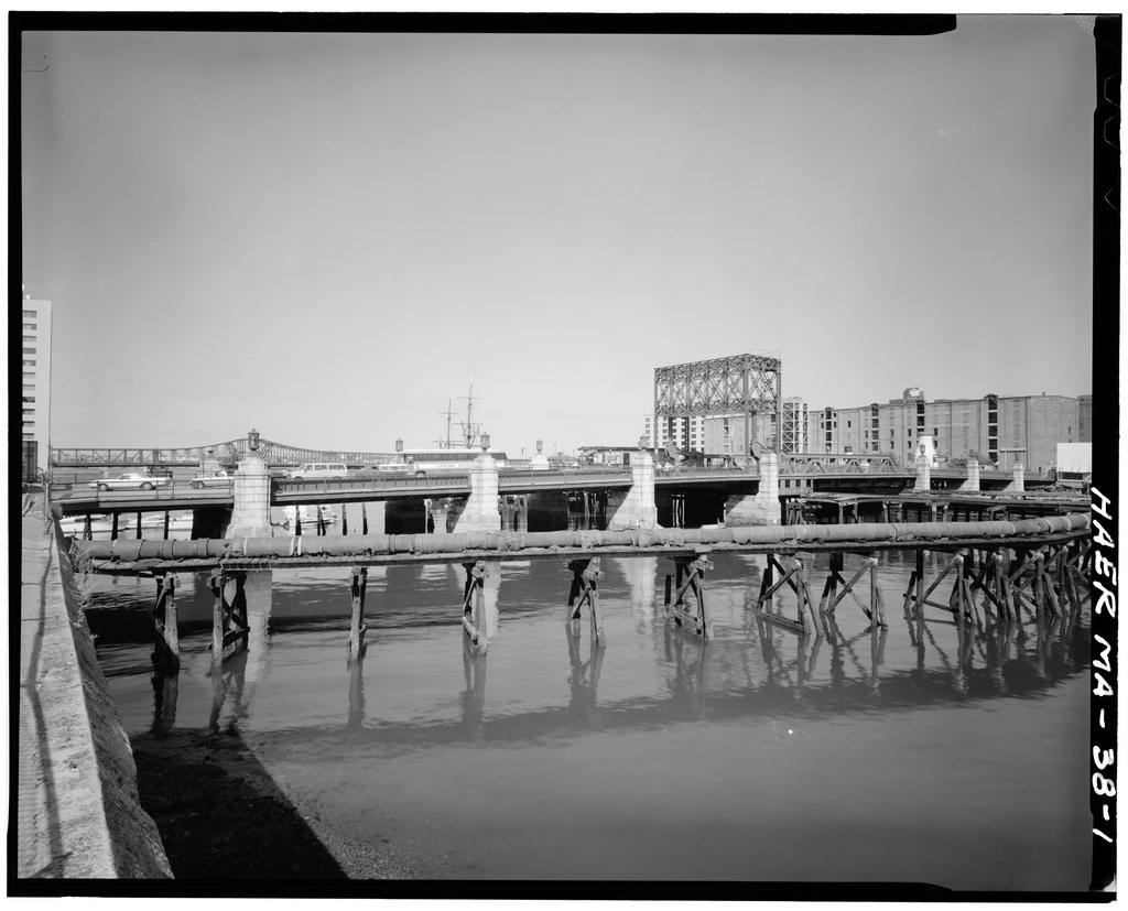
MA-37) - Congress Street Bascule Bridge (Strauss overhead counterweight bascule, HAER No. MA-38). - Summer Street Retractile Bridge (paired retractile draw, HAER No. MA-41) - South Station Old Colony Railroad Bridge (Scherzer rolling lift, HAER No. MA-35) - Broadway Swing Bridge An earlier railroad swing bridge was built in at the Summer Street site by the New England Railroad (originally the Midland Railroad) to reach its passenger and freight terminals at Dewey Square near today's South Station. The railroad was discontinued in by an Act of Chapter which provided for the extension of Summer Street across Fort Point Channel.2 The present Summer Street Retractile Bridge was built in as a result of the efforts of Boston Wharf Company President Joseph B. Russell.
Its construction marked the beginning of extensive relocation of wool warehouses from the Dewey Square area to new warehouses constructed across Fort Point Channel in South Boston, particularly by the Boston Wharf SUMMER STREET RETRACTILE BRIDGE HAER No. MA-41 (page 4) Company. The bridge thus has cultural associations with the development of South Boston. It also has historical interest as the site of the trolley disaster. The bridge is a familiar landmark to Boston Harbor and automobile traffic, and is visible from other nearby landmark bridges. The bridge was constructed for the City of Boston by the Berlin Iron Bridge Company under the direction of the Boston Public Works Department, and linked downtown Boston with the South Boston waterfront to the southeast.
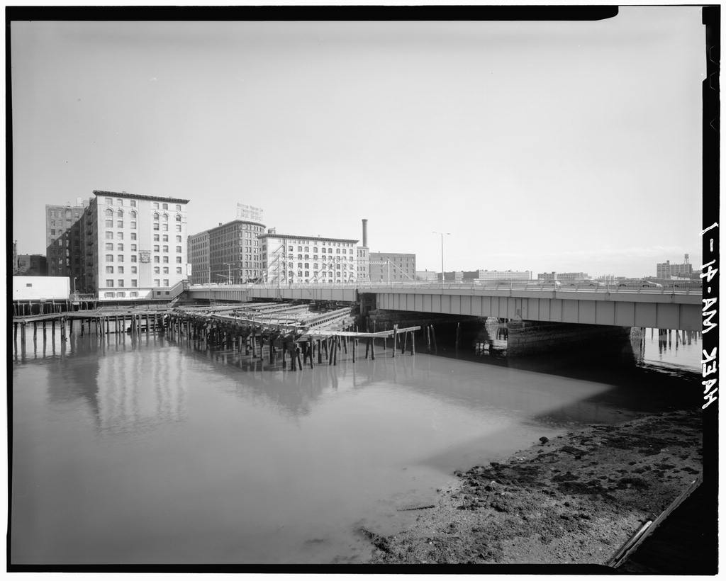
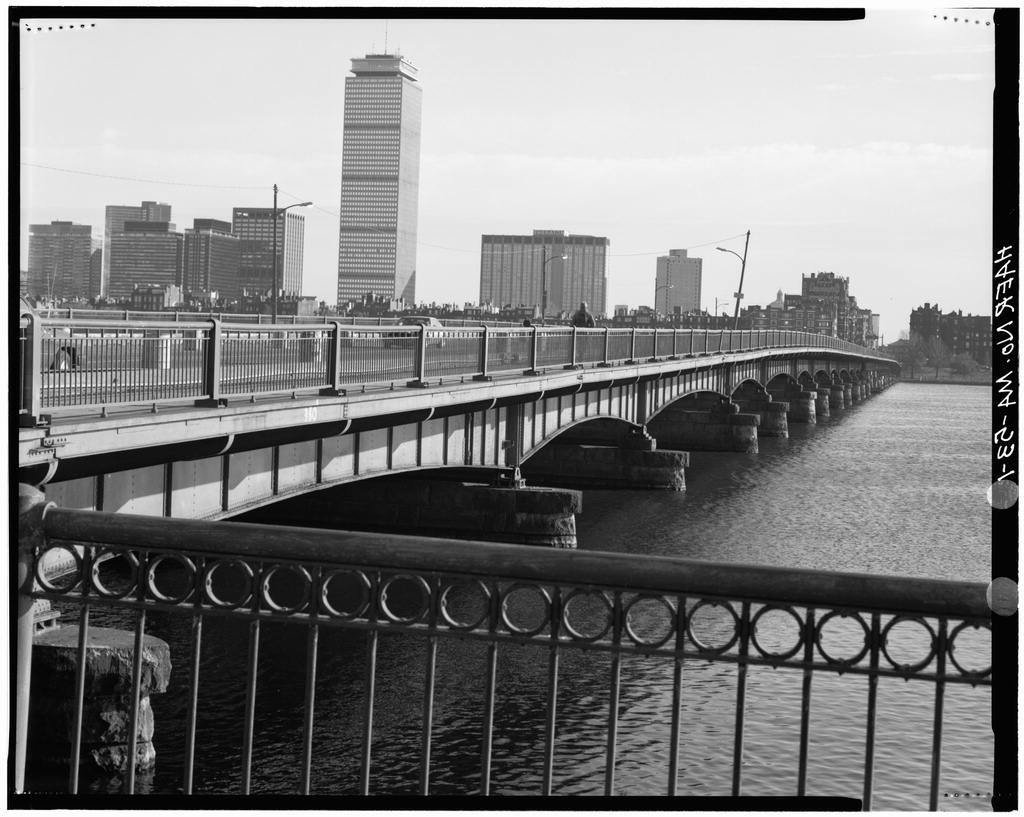
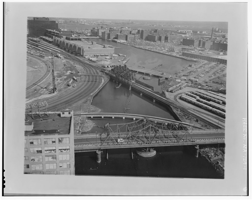
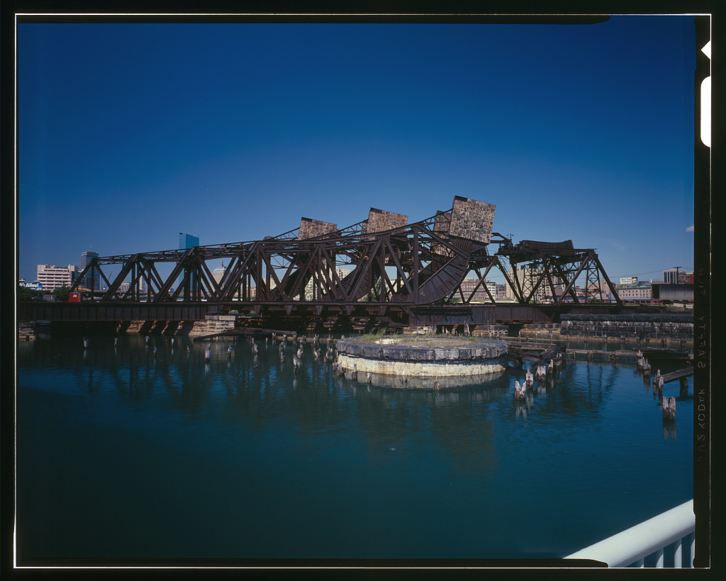
The paired retractile draw is located on Fort Point Channel between Dorchester Avenue on the northwest and the Boston Wharf Company properties on the southeast. The draw sections are at the center of the bridge which is supported between masonry abutments by four fixed-span masonry piers and a series of wood bents under the retractile rails. On the north side toward the harbor at the west end is the Federal Reserve Bank, and at the east end are the Boston Wharf Company buildings in the proposed Fort Point Channel Historic District. On the south or upstream side at the west end is South Station, and on the South Boston end are the six and seven-story masonry Boston Wharf Company buildings in the proposed historic district.
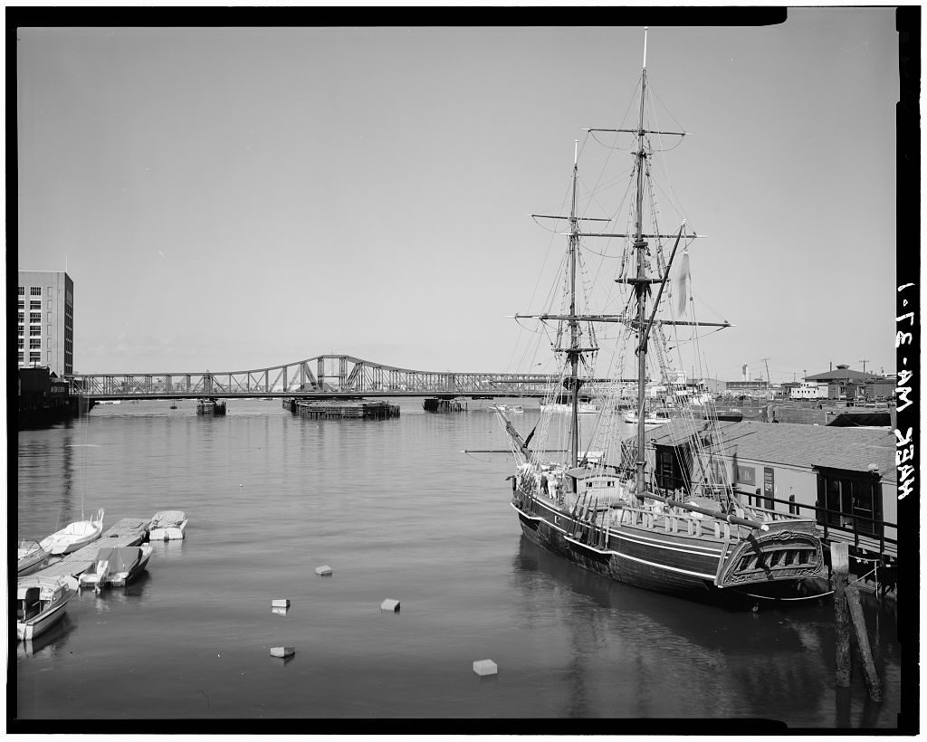
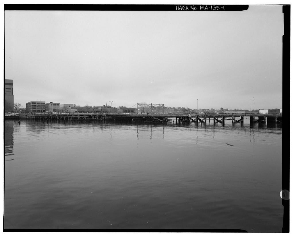
The bridge is a major vehicular and pedestrian route to the South Boston commercial-industrial area from South Station and the downtown Boston business district.3 Fort Point Channel is a tidal estuary which serves as anchorage for fishing, shellfishing and lobstering vessels, as well as pleasure boats and rowing shells. Boston Harbor is located to the northeast on the other side of the adjacent Congress Street Bascule Bridge (HAER No. MA-38) and Northern Avenue Swing Bridge (HAER No. MA-37). The tidal basin between the Summer Street and the Congress Street bridges is presently crossed by two water mains and marked by numerous old fender piles.
The Summer Street Retractile Bridge is no longer operable due to extensive deterioration of the bridge structure and its pilings and the loss of its Tender's House, pedestrian waiting shelters and gates, which have greatly compromised its historic integrity. The bridge has been determined eligible for listing on the National Register of Historic Places.4 Design Context The Summer Street Retractile Bridge of represents the culmination of the evolution of a bridge type which was developed and primarily utilized in Boston.
A little-known engineer, Luther Drew, working with City Engineer James Slade, appears to have pioneered the retractile bridge form as attested by his drawing for the Federal Street (now Dorchester Avenue) Bridge of the earliest known structure of this type.5 The drawings for a "Slide Draw" (in the City Engineer's Bridge Collection in the Boston Public Library) were signed by both Drew and Slade. The draw span had Samson posts (upright vertical posts supporting SUMMER STREET RETRACTILE BRIDGE HAER No. MA-41 (page 5) tension stays. See drawing HAER Photo No. MA-41-30) with stays tightened by turnbuckles to support a diagonal retractile draw system.
Luther Drew is listed in Boston city directories as an engineer living at 105 Boylston Street from to The shipfitter's characteristics of the cantilevered, timber structure supported by metal stays, suggest he may have been a relative of the Drew family involved in the manufacture of shipbuilding tools and foundry work at Kingston and Plymouth on the South Shore.6 James Slade is listed as a civil engineer with his home at 1 Canton Place in and at 53 Indiana Place in Little else is known about either man at present but their early bridge design of had a seminal role in the development of the retractile bridge type.
Although the stay-support system was utilized in the construction of only a few bridges in the nineteenth century, including in the nearby Summer Street Bridge over Fort Point Channel, it has recently regained prominence in contemporary bridge design. The most recent bridge designs for Boston's Central Artery Charles River Crossing include proposed cable- stayed bridge concepts. Thomas Willis Pratt the noted civil engineer and inventor, died twenty-five years prior to the completion of the Summer Street Retractile Bridge. However, Pratt also had a significant role in the development and refinement of the retractile drawbridge type in Boston. During the Federal Street Bridge over Fort Point Channel was rebuilt as a double retractile draw by the City.
The annual report at the time stated "each of these draw-bridges has two Pratt trusses." 7 Pratt was then involved as Superintending Engineer for the city on the construction of the adjacent Broadway Bridge built in over the Channel. In Pratt also patented a system "equalizing the weight borne upon the wheels and carriages" 8 - a retractile draw support system apparently developed during the concurrent rebuilding of the Federal Street Bridge. This truck system evidently tied together his experience working for various railroads (he was Chief Engineer for the Eastern Railroad from until his death) with his expertise in bridge design.
The Boston Public Library's comprehensive City Engineer's Bridge Collection includes drawings of the Federal Street Bridge dated to for various proposals for innovative wood and iron drawbridges. These proposed designs, for retractile as well as alternative schemes for "Side-Pivot Turn-Table Draw" and Swing Bridges "Not Adopted", are unsigned; however, Pratt served as consultant to City Engineer Nathaniel H. Crafts and his successor Joseph P.
Davis, under whose direction the drawings were prepared.9 The adopted design for the Federal Street Bridge (rebuilt in has composite wood/metal Pratt trusses (similar in form to Pratt's patent truss design) with a curved top chord which he patented on April A November drawing for a support system of trucks, although stamped "Not Adopted", is very similar to the four-wheeled trucks used over twenty-five years later on the Summer Street Retractile Bridge (HAER Photo No. MA- Other innovative drawings include those for a "Proposed Wrought Iron Slide Draw" - a retractile draw entirely of wrought iron including a metal pan deck - dated December It appears that these drawings were resurrected for the reconstruction of the Federal SUMMER STREET RETRACTILE BRIDGE HAER No.
MA-41 (page 6) Street Bridge for which the August drawings show a similar retractile bridge structure entirely of iron with the exception of the wooden deck. With its iron girders, Samson posts, supporting stays and pipe railing, this design was the immediate predecessor of the Summer Street Retractile Bridge. The original drawings show that the Federal Street Bridge was a horse-powered, rack-and-pinion drive, counter-weighted, retractile draw based upon the earlier precedent by Drew and Slade. The alternative designs which were not adopted pre-dated the Summer Street Retractile Bridge by over twenty-five years yet apparently served as design sources for the later bridge.
The early, seminal drawings in the City Engineer's Bridge Collection in the Boston Public Library are extremely important and deserve further evaluation as the basis of the later design for the reconstruction of the Federal Street Retractile Bridge in This iron retractile draw was the immediate prototype for the Summer Street Retractile Bridge. A design for an "Iron Centre Pivot Turn Table Draw" dated July as well as another design "Not Adopted" for an iron truss swing bridge supported on iron pilings with arched connectors has relevance to the study of alternative bridge designs of the period.
The Broadway Bridge's early iron screw pilings failed, requiring its reconstruction in This may offer insight into the reasons for selection of the proven retractile bridge form which was often was used elsewhere: in over the Charles River to City Square in Charlestown (Warren Bridge, rebuilt in demolished), in the widening of Federal Street, in a double retractile constructed in at Dover Street (now the Fourth Street Bridge to South Boston), again in the rebuilding of Federal Street Bridge in and finally at Summer Street and its Extension over the Reserved Channel (the last active bridge of the type) in The Federal Street Bridge drawings not only shed light on the history and evolution of the retractile bridge as a type, but also illustrate the great diversity of design solutions under consideration by engineers during the nineteenth century.
The Summer Street Retractile Bridge of which replaced an swing bridge, was preceded by earlier structures at nearby bridge crossings over Fort Point Channel. Previous swing bridges crossed to South Boston at Mount Washington Avenue and Congress Street The Summer Street Retractile Bridge was built based upon the immediate precedents of the earlier Dover Street Retractile Bridge demolished) and the Federal Street (now Dorchester Avenue) Bridge demolished by the USPS and replaced by a fixed span in the Of the eight retractile bridges built by the City before only two remain: the Summer Street Retractile Bridge over Fort Point Channel and the single-leaf retractile bridge at the other end of Summer Street over the Reserved Channel.
Construction and Alterations The history of the Summer Street Retractile Bridge including its original construction, rebuilding, repairs and maintenance is well-documented in the collections of the Bridge SUMMER STREET RETRACTILE BRIDGE HAER No. MA-41 (page 7) Division of the Boston Public Works Department (records of active bridges kept at 400 Frontage Road in South Boston) and the annual reports of the earlier Bridge and Ferry Division, as well as other photographic collections such as those of the Bostonian Society and newspaper archives. The original and existing condition of both the site and the bridge are documented by the drawings and photographs accompanying this text.
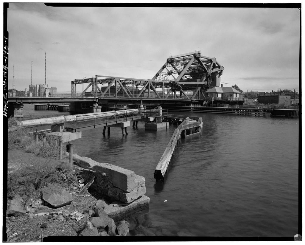
The Summer Street Retractile Bridge, a paired-leaf oblique retractile bridge, has each barrel constructed of three deck-plate girders. A portal frame on each draw span consists of a pair of Samson posts which carry the ends of pinned eyebar stays which help support the cantilevered section of the draw span when the bridge is open. The general plans for the bridge were approved by the Board of Harbor and Land Commissioners on September 7, The necessary authority to construct the bridge and sea walls was obtained from the U.S. Government through the Secretary of War on September The bridge was apparently the design of Boston City Engineer William Jackson who signed the drawings, possibly with the help of Assistant City Engineer John E. Cheney.
It was built in conjunction with the planned extension of Summer Street to South Boston. Contracts for building the west abutment were awarded on October 7, and the masonry abutments and piers were completed December The steel superstructure of the fixed spans was completed June and the timber piles for the draws and necessary draw piers in August of The first of the two draws was put into service on August 14, powered by a temporary steam plant until electricity was installed. The new street approaches and operation of the draw bridge were turned over to the Boston Street Department on January 26, The draw foundation and piers were built by W. J. Lawler. The Berlin Iron Bridge Company of Berlin, Connecticut built the draws and A. & P. Roberts Company built the fixed spans.
The Coffin Valve Company supplied the trucks and General Electric supplied the draw machinery which was built by Miller and Shaw. The cost of the bridge together with the Summer Street Extension, 100 feet wide and over feet long, was as of according to city records. The total expense was divided among the Commonwealth the City of Boston and the Railroad Company One of the major costs of the extension was the Summer Street Viaduct bridge in South Boston, built over the New York, New Haven and Hartford Railroad tracks at the railroad's expense.11 The Summer Street Retractile Bridge has undergone repairs and alterations as follows: Rebuilding of draw span and foundation. Strengthening of floor beams for street cars and 46-ton express freight cars. Repairs to piers, struts and draw span.
SUMMER STREET RETRACTILE BRIDGE HAER No. MA-41 (page 8) Repairs and rebuilding of draw span. Made a fixed bridge and closed to trucks and busses. Tender's House, pedestrian shelters and gates removed. Roadbed floor framing reconstruction and strengthening of superstructure. Roadbed paving and repairs. Roadbed and stringer repairs. Roadbed and stringer repairs. General maintenance over the years has included painting and miscellaneous minor repairs such as installation of steel patch plates and additional light fixtures; machinery, gate and railing repairs; and grouting of the mortar joints in the granite piers. The bridge is presendy in a fixed position and inoperable.
Recent structural rating reports on the bridge have found evidence of major decay and an extensive rehabilitation is now being designed to correct these deficiencies.12 Kev Individuals The Summer Street Retractile Bridge was built in response to the development efforts of the Boston Wharf Company as reported in its Centennial History of The bridge was apparently designed by Boston City Engineer William Jackson who signed the drawings, possibly with the help of Assistant City Engineer John E. Cheney. The Berlin Iron Bridge Company built the draws while A. & P. Roberts Company constructed the fixed spans.
The nationally significant Berlin Iron Bridge Company of East Berlin, Connecticut was started as the Corrugated Metal Company which began making roof trusses in the mid-1870s and bridges about The firm was particularly noted for its patented lenticular truss bridges. Many of these were built in Massachusetts and nine surviving examples of the company's bridges have been identified in the Massachusetts Highway Department's Historic Bridge Survey. The name was changed to the Berlin Iron Bridge Company in and the company was acquired by the American Bridge Company in The Summer Street Retractile Bridge would thus be one of the last produced by the original Berlin Iron Bridge Co., and tests reveal that the bridge was built of steel rather than iron.
This may be explained by the fact that some drawings are signed by the Pencoyd Iron Works, Bridge and Construction Department. The Pencoyd Iron Works was located in Philadelphia, SUMMER STREET RETRACTILE BRIDGE HAER No. MA-41 (page 9) Pennsylvania and was identified in the advertising of the firm as being operated by A. & P. Roberts Company, designers and builders of train sheds, viaducts, elevated railroads and all- steel structures. A.& P. Roberts began fabricating bridges about and were the contractors for the fixed spans of the Summer Street Retractile Bridge. This company, like the Berlin Iron Bridge Company, was also acquired by the American Bridge Company in Other firms which contributed to the construction effort were W. J.
Lawlor and Ross & Fowler, draw foundations, piers and abutments; Coffin Valve Co. and Swett Car Wheel & Foundry Co., trucks; Miller and Shaw, draw machinery; and General Electric, motors.13 Alterations to the Summer Street Retractile Bridge since its original construction have been substantial. In Boston Engineering Department Bridge Division Engineer John E. Carty planned the strengthening of floor beams for street railway cars. Repairs and alterations in succeeding years were undertaken by Boston Public Works Department engineers including John J.
McCall, Division Engineer, who superintended the repairs, and Charles Martin, Division Engineer, who superintended major repairs and reinforcement of the roadbed, superstructure and railings in Subsequent repairs have been done in consultation with Lawrence J. McCluskey, P. E., Senior Vice President of Seelye Stevenson, Value and Knecht, present engineering consultants to the department. In the past decade Balfour Engineering Co. Inc. has executed repairs and provided mechanical services. The draw is no longer in operating condition; it was made a fixed bridge in Construction Techniques - Technical Description a.
Original Construction Foundations - The existing channel was dredged to 50 feet in width and 16 feet in depth according to the provisions of the license granted by the Board of Harbor and Land Commissioners. Piles were driven after borings revealed a layer of clay extending to about 40 feet below the city base with sand and gravel at 50 feet. The granite rock-faced masonry foundations were built on concrete footings which rest on wood piles below the channel. The spruce piles were said to have been driven both vertically and at an inclination of thus spreading the load over a wider area. The concrete foundations were poured using cofferdams of six-inch splined spruce sheeting driven at a inclination as forms, and cut off at elevation 0, the city base.
The concrete used in the foundations was one part Portland cement, two parts sand and four parts gravel. The top foot of each foundation was poured separately, rammed and smoothed to receive the stone pier. Similar foundations support the abutments. Piers and abutments - The piers above the foundation are built of Cape Ann granite laid in solid Portland cement mortar, with exposed surfaces of quarry or rock-faced granite. The bottom course is composed of all headers, while the remainder of the piers are in Flemish SUMMER STREET RETRACTILE BRIDGE HAER No. MA-4I (page 10) bond, with all headers extending through the pier. The space between the stretchers is rilled with Portland cement of the same mix as the foundations. The top coping stones at the ends are doweled into the course below.
The westerly abutment on the Boston side is a granite masonry structure bonded with the old seawall of the channel. The easterly abutment on the South Boston side has return walls extending about 35 feet back along both street lines; here the old seawall was spanned with the addition of five lines of 15-inch steel I-beams built into the masonry. The four fixed-span piers are rectangular in plan with upstream and downstream ends tapered to a point. The battered section of the piers is topped by a wider coping which terminates where its supports the main girders below the bridge deck.
The retractile pier which supports the draws is constructed of piles similar to other retractile draws built in Boston, with the exception of the substitution of steel I-beams, 20 inches deep which support hard pine timbers as the upper track stringers. The draw fender pier, comprised of wood piles braced and partially decked with hard pine, support the Tender's House, a half-timber structure on the southwest side of the draw. The five-span bridge has a total length of 507 feet. Approach (Fixed) Spans - Four riveted fixed spans, two on the Boston and two on the South Boston side of the draw, were numbered one to four on the drawings. The fixed spans are made up of three lines of deck-plate girders, with transverse deck girders and longitudinal floor beams.
Each approach span had a roadway constructed of 6-inch hard pine floor timbers resting in 5" x 6" hard pine sleepers which were fastened to the longitudinal steel floor beams. The approach span floor beams were in turn supported by transverse I-beams resting on the main longitudinal girders. The approach span floor paving, originally consisted of 6-inch granite blocks laid with pitch joints. Sidewalks were originally 4 inches of asphalt laid on 4- inch thick plank. Railings were pipe railings with round spindles. At the South Boston end of the draw span, cantilevered landing blocks are attached to the ends of the main girders of the fixed span in order to support the toe end of the draw when closed.
The cruciform, wood-frame Tenders' House founded on wood piles at the Boston end of the approach had wood-shingled side-walls, half-timbering in the west gable end and a slate hipped roof on the south and east ends. Draw Span - The draw spans of the bridge, a paired-leaf (each single-barreled) oblique retractile bridge, have each barrel constructed of three lines of riveted deck-plate girders. Lateral cross-bracing for the draw span decks is provided by crossed diagonal tie rods. A portal frame is on each draw span, consisting of a pair of Samson posts carrying the ends of pinned eyebar stays which help support the cantilevered section of the draw span when the bridge is open. Angled struts support the eyebars near the midpoint.
Four single-truck and three-double truck carriages support each draw span. The trucks do not appear to be of the Pratt patent type, and the cast wheels are inscribed "Swett Car Wheel & Foundry, Chelsea, Mass. The SUMMER STREET RETRACTILE BRIDGE HAER No. MA-41 (page 11) draw span piers support the draw rails on steel-and-timber runways angled at 45 to the bridge. A timber pile runway pier supports the draw machinery, drum, gearing, and electric motor. The 132 foot wide draw leafs span a 60 foot wide channel. The steel laced-struts, Samson posts and crossbars provide lateral stability as well as additional lengthwise support to the cantilevered drawbridge upon opening.
The draw span of the bridge was assembled in an open position, and closed upon completion of the truss and machinery assembly. When closed, the bridge ends are supported on cast iron shoes supported by cantilever girders projecting from the fixed span piers opposite. At the opposite end they are supported by the rear girders by means of a pin connection. Counterbalance for the draw when open is provided by cast-iron boxes filled with lead. The draw spans originally had a 2-inch spruce decking resting on 4-inch kyanized 14 (treated) spruce timbers which in turn rested on longitudinal hard pine joists. These joists in turn rested on transverse I-beams which carried the weight to the longitudinal main steel girders.
The draw sidewalks were of 2-inch hard pine plank resting on hard pine joists. b. Repairs and Alterations In reinforcement for street cars and 46-ton express freight cars was accomplished with the strengthening of floor beams. Between and repairs to piers, struts and the draw span were carried out. Mortar joints in the piers between high and low tide were cleaned and shot full of gunite in and the steel superstructure was cleaned and painted. On June the steamship "Baron Murray," heading upstream, fouled the northerly draw leaf by striking the corner fascia beam. The draw leaf was knocked off its trucks and onto the draw tracks; one draw truck dropped overboard. The City's Bridge Division, assisted by W. H. Ellis & Son Co., made the necessary repairs.
In the draw span was cleaned and painted by Eugene Riccardelli. New headers were placed in In repairs included the addition of a steel counterweight to properly balance the bridge and the reconstruction of the draw span foundation and deck. In the retractile draw was fixed and closed to trucks and busses. After the Tender's House, pedestrian shelters and gates were removed. In repairs included the reconstruction of the roadbed floor framing and strengthening of the superstructure. Supplemental trusses were inserted beneath transverse floor beams. In roadbed repairs and paving were undertaken; the bridge is presently covered by asphalt pavement on the approach spans with open steel grating on the draw spans.
Since periodic roadbed and stringer repairs have been made, culminating in the recent emergency repairs. Wood fender piers have badly deteriorated in intervening years, although they retain their original configuration. The bridge is presently in a severely deteriorated condition and requires extensive repair; its structural load rating has been reduced from 19 tons to 8 tons. SUMMER STREET RETRACTILE BRIDGE HAER No. MA-41 (page 12) Bridge Description and Operation The bridge has a steel superstructure which rests on granite block piers and abutments; these in turn are supported by concrete foundations and friction piles. The Summer Street Retractile Bridge consists of five spans: the four principal fixed spans are paved-deck, steel plate-girders averaging 80 feet on support bearings.
Each of the two center draw spans is a single-leaf, open-grate deck, retractile draw; each is 132 feet in length on the centerline to its cantilever leaf end which spans the 60 foot wide channel. Each deck is 44 feet wide and consists of a roadway and a sidewalk. The two bridge leaves together carry four vehicular lanes and two sidewalks. The fixed spans are comprised of three lines of deck-plate girders with transverse floor beams and longitudinal stringers. Lateral cross-bracing for the draw span decks is provided by crossed diagonal tie rods. The center draw span has lateral bracing between two Samson posts, with an plaque in each of the two portal crossbars.
The center portal, about 25 feet high measured from the bridge deck and spanning 45 feet, carries the cantilevered bridge when it is open by means of diagonal braced struts. The draw section travels on four single-truck and three double-truck carriages which support each draw span. When opening, the carriages run on draw rails supported on steel and timber runways angled at 45 to the bridge. The retractile draw machinery, drum, gearing and electric motor are supported on the timber pile runway pier. When closed, the bridge ends rest on cast-iron shoes supported by cantilever girders which project from the opposite fixed-span piers. The bridge was operated by a draw tender with gate men to operate the gates.
The original operating mechanism consisted of a system of cable winches powered by two street-car electric motors. The winches were independently mounted on the draw piers at the centerline of the tracks and the center of gravity of the bridge. Each motor was geared to a horizontal drum 3 feet in diameter from which two cables were extended, each attached to the bridge at its center of gravity. One cable passed over a sheaf at the channel face of the foundation; winding one or the other of these two cables onto the winch drum opened or closed the draw. Each motor was operated by a controller in the Controller's House, located between the draws near the face of the channel. One person could operate both draws. A manual crank-drive system was provided in case of electrical failure.
The machinery was organized to include two cable winches, gears and two main drive motors (see operating machinery drawings). Brake levers controlled the opening speed of the draws. Latches were provided at the landings so that the draws were automatically locked when closed. Gates were manually operated by gate men. In addition to the Controller's House, a Tender's House was located on the southwest fender pier and contained an office, work room and locker room. Two open-sided, hip-roofed waiting shelters were provided for pedestrians. Crook-necked street lamps provided lighting, as shown by original drawings and early photographs. SUMMER STREET RETRACTILE BRIDGE HAER No.
MA-41 (page 13) The draw was opened by the two electric motors with drive trains attached to the pier and attached by cables to the draw. These two sets of apparatus, each protected by a boxed enclosure, could operate independently. Four gates at each end of the bridge were operated manually from the roadway deck by the gate men. When the draw was closed, the gates were opened and traffic passed onto the draw. The system worked successfully except on election night in November when a trolley full of voters failed to stop at the open draw and plunged into Fort Point Channel resulting in the loss of fifty-two lives. The tragedy is described in an article in the Patriot Ledger by correspondent Thomas J. Holbrook.
The disaster was attributed to a failed signal lantern and the driver's inability to fully stop the trolley in time to avoid plunging through the gates into the channel. After restoration of the gates the Summer Street Retractile Bridge continued to serve trolleys until the bridge roadbed was rebuilt and the span made permanently fixed in the i SUMMER STREET RETRACTILE BRIDGE HAER No. MA-41 (page 14) NOTES 1 Central Artery/Tunnel FSEIS/R Inventory of Historic Resources, South Boston, pp. 59 - 66. 2 Stott, Peter. Bridge Row, The Drawbridges of Fort Point Channel, pp Roper, Stephen. Historic Bridge Inventory, Survey Form, August Spengler, Albert. Legal History and Cost Records of... Bridges. W.P.A. Project File No. 56. 3 Boston Public Works Department Annual Report, Bridge Division Records.
4 Bridge Inventory, Survey Form, August Inventory of Historic Resources, Central Artery/ Third Harbor Tunnel, April Figure 5. 5 Boston Public Libray, Director's Office. Bridge Collection - Drawings from the City Engineer's Department. 6 Stone, Orra. History of Massachusetts Industries, 7 Boston City Auditor's Report pp. 8 U.S. Patent Office List Patent No. - Draw-Bridge. - T. Wilis Pratt, Boston, Mass. Feb. 9 Boston Public Libray. Bridge Collection - Federal Street Bridge. City Documents Annual Report, 10 Condit. American Building Art. p. National Cyclopedia "Pratt, Thomas Willis." v. P, p. 11 Boston Engineering Department Annual Reports, - Bridge Inventory Form; Bridge Division Records, WPA Project File No. 56; Stott, Peter. Notes on Summer Street Bridge.
12 Boston Public Works Department, Bridge Division Records. Seelye Stevenson Value & Knecht, Engineers and Planners, Engineering Files. 13 Schrock, Nancy, Architectural Records in Boston, Cambridge, & Vicinity , p. 17. Eldredge, Joseph L. Architecture Boston, pp. 17 . Galer, The Boston Bridge Works, pp. Darnell, Victor C, Directory of American Bridge Building Companies, pp. 76. 14 kyanized : wood treatment, after Kyan, Jr. inventor of the process to make wood resistant to decay by treatment with a solution of corrosive sublimate, probably a distillate such as creosote. SUMMER STREET RETRACTILE BRIDGE HAER No. MA-41 (page 15)
Boston, City of, and the Fort Point Citizens Advisory Committee, jointly with the Boston Redevelopment Authority. Fort Point Channel Plan Progress Report.* March Boston, City of. Boston Engineering Department Annual Reports. Boston Public Library. Boston, City of. Boston City Auditor's Report Boston City Directories, Boston City Documents, Annual Reports of the City Engineer, BRA, The Bridges Over and Thru the Fort Point Channel, unpublished Boston, Central Artery/ Tunnel. Bridge Design Review Committee. Report on the Charles River Crossing. (Boston, Central Artery/ Tunnel. Inventory of Historic Resources. Agency Review Draft, April, Condit, Carl W. American Building Art, Nineteenth Century Oxford Univ. Press, Darnell, Victor C.
Directory of American Bridge Building Companies, (Washington, Society for Industrial Archeology, and S.LAJournal article on the Berlin (Connecticut) Iron Bridge Co. Eldredge, Joseph L. The Boston Society of Architects. Architecture Boston, (Barre, MA: Barre Publishing, Galer, Gregory Jay. The Boston Bridge Works, Thesis, Brown Univ., June, Greater Boston Chamber of Commerce. Physical Change and Programming in and around the Fort Point Channel, a Report of the Fort Point Channel Project, M. David Lee, Chairperson, July SUMMER STREET RETRACTILE BRIDGE HAER No. MA-41 (page 16) National Cyclopedia ofAmerican Biography. "Pratt, Thomas Willis" Roper, Stephen J. Massachusetts Department of Public Works (now Massachusetts Highway Department) Historic Bridge Inventory\ May-Oct. Schrock, Nancy.
Architectural Records in Boston, Cambridge, & Vicinity (New York, Garland Publishing, Spengler, Albert. Legal History and Cost Records of City of Boston Bridges. W.P.A. Project File No. 56 of WPA Official Project ca. Stone, Orra. History of Massachusetts Industries, 3v. (Boston: S J. Clarke Publishing Co. Stott, Peter. Bridge Row: The Bridges of Fort Point Channel, unpublished typescript, Boston, June Stott, Peter. Notes on Summer Street Bridge. Quotation from One Hundred Years of the Boston Wharf Company (Boston: Boston Wharf Co., p. 17. Todd Lee / Clark / Rozas Associates, Inc. Northern Avenue Bridges Study, for the Boston Redevelopment Authority, Boston, May U.S. Patent List. Patent No. Draw-Bridge- T. W. Pratt, Boston, Mass. Feb.
Boston Public Works Department, Bridge Division Records, 400 Frontage Road, South Boston, Massachusetts, Boston Public Library, 666 Boylston Street, Boston, Massachusetts, Government Records, Print Department, Director's Office Bridge Collection - City Engineer's Bridge Dept. Drawings. Seelye Stevenson Value & Knecht, Engineers and Planners, 230 Congress Street, Boston, Massachusetts, Engineering Files. SUMMER STREET RETRACTILE BRIDGE HAER No. MA-41 (page 17) Location Plan - South Bay Area of Boston. From USGSMap: Quad: Boston, South, scale, I/// P cm ra SUMMER STREET RETRACTILE BRIDGE HAER No. MA-41 (page 18) Historic Drawing, Summer Street Bridge over Fort Point Channel, Annual Report of Boston Engineeering Department, SUMMER STREET RETRACTILE BRIDGE HAER No.
MA-41 (page 19) Historic View, Berlin Iron Bridge Co., fabricator of the Summer St. Retractile Bridge. Darnell, Directory of American Bridge Building Co's, M "9 -4 O <M M - *s ^ +* 5 . =- 2 > sfi Is o TS .a O 7 00 Jt rt M W " 2 IK o 8<n 4 * si H M O .* P. M ft O ?* a I SUMMER STREET RETRACTILE BRIDGE HAER No. MA-4I (page 20) Historic View, Summer Street Retractile Bridge over Fort Point Channel. Annual Report of the Boston Engineering Dept, O u. K Ul > o UJ a K CO SUMMER STREET RETRACTILE BRIDGE HAER No. MA - 41 LIST OF DRAWINGS (page 21) Boston Public Works Department - Summer Street Retractile Bridge No. Drawing Title/ Description JSoJes Aeencv/Engineer 733 "Summer St. Extension, "Changes made "to "Wm Jackson, City Abutment" correspond to construction" Engineer" 726 Masonry Piers E.
Abutmt. Congress St. Grade Boston PWD - Crossing Bridge Div. 731 Masonry Piers E. Abutmt Stone Coursing Boston PWD - Bridge Div. 732 Draw foundation & fender Piers Boston PWD - Bridge Div. 730 Shows "old bridge abutment" "old wall to remain" buried "Wm Jackson, City under. Engineer" 729 Summer St. Extension E. "Wm Jackson, City Abutment Engineer" C83 Layout Ironwork shop drawings "Pencoyd Iron, (Order No.) Bridge & Const. Dept." 724 Parapet for abutment Stone "Wm Jackson, City Engineer" 758 Half Section of Bridge, Detail "Changes made to 'Boston Eng. Dept, of Fl. & Railing correspond with Wm. Jackson" Construction" 757 "Plates, Shoes, Castings, Etc." 'Boston Eng. Dept, Wm. Jackson" 756 Sway Frames "Boston Eng. Dept Wm. Jackson' SUMMER STREET RETRACTILE BRIDGE HAER No.
MA - 41 LIST OF DRAWINGS (page 22) Boston Public Works Department - Summer Street Retractile Bridge No. XS&E Drawing Title/ Description Notes Agency/Engineer 755 Stringers "Boston Eng. Dept., Wm. Jackson" 754 Sidewalk Beams & Fascias "Boston Eng. Dept, Wm. Jackson" 753 Floor Beams at Boston "Boston Eng. Dept, Abutment Wm. Jackson" 752 Floor Beams "Boston Eng. Dept, Wm. Jackson" 751 Girder C4 "Boston Eng. Dept, Wm. Jackson" 750 Girder B4 "Boston Eng. Dept, Wm. Jackson" 749 Girder A4 "Boston Eng. Dept, Wm. Jackson" 748 Girder C3 "Boston Eng. Dept, Wm. Jackson" 747 Girder B3 "Boston Eng. Dept, Wm. Jackson" 746 Girder A3 "Boston Eng. Dept, Wm. Jackson" 745 Girder C2 "Boston Eng. Dept, Wm. Jackson" SUMMER STREET RETRACTILE BRIDGE HAER No.
MA - 41 LIST OF DRAWINGS (page 23) Boston Public Works Department - Summer Street Retractile Bridge No. Year Drawing Title/ Description oJgg Agencv/Engineer 744 Girder B2 "Boston Eng. Dept., Wm. Jackson" 743 Girder A2 "Boston Eng. Dept, Wm, Jackson" 742 Girder Fl "Boston Eng. Dept, Wm. Jackson" 741 Girder E "Boston Eng. Dept, Wm. Jackson" 740 Girder Dl "Boston Eng. Dept, Wm. Jackson" 739 Girder C (details) "Boston Eng. Dept., Wm. Jackson" 738 Girder B "Boston Eng. Dept, Wm. Jackson" 737 Girder A "Boston Eng. Dept, Wm. Jackson" 736 General Plans Spans 3 & 4 "Boston Eng. Dept, (inactive) Wm. Jackson" 735 General Plans Spans 1 & 2 "Boston Eng. Dept, (inactive) Wm. Jackson" 728 Summer St. Extension Piers Boston Eng. Dept. SUMMER STREET RETRACTILE BRIDGE HAER No.
MA - 41 LIST OF DRAWINGS (page 24) Boston Public Works Department - Summer Street Retractile Bridge No. Year Drawing Title/ Pescriptipn Notes Agency/Engineer C 83 d - Castings for Summer St. Bridge Ironwork shop "Pencoyd Iron, Bridge & Const.
Dept" C 83 a-7 Span 2 (Girders A2 R & L) Ironwork shop "Pencoyd Iron, Bridge & Const Dept." C 83 a-4 Span 1 (Girders Al & Fl Ironwork shop "Pencoyd Iron, Bridge & Const Dept" C 83 a-3 Buckle Plates Ironwork shop "Pencoyd Iron, Bridge & Const Dept" C 83 a-2 Shoes & Rollers Ironwoik shop "Pencoyd Iron, Bridge & Const Dept." C 83 a-16 Cross Frames & Struts Ironwork shop "Pencoyd Iron, Bridge & Const Dept." C 83 a-15 Sidewalk Stringers Ironwork shop "Pencoyd Iron, Bridge & Const Dept." C 83 a-14 Floor Beams Ironwork shop "Pencoyd Iron, Bridge & Const Dept" C 83 a-13 Floor Beams Ironwork shop "Pencoyd Iron, Bridge & Const Dept" C 83 a-12 "Span 4 (Girders B4 R, B4 L, Ironwork shop "Pencoyd Iron, C4 R, C4 L)" Bridge & Const Dept." C 83 a-11 "Span 4 (Girders A4 R, A4 L)" Ironwork shop "Pencoyd Iron, Bridge & Const Dept" SUMMER STREET RETRACTILE BRIDGE HAER No.
MA - 41 LIST OF DRAWINGS (page 25) Boston Public Works Department - Summer Street Retractile Bridge No. Year Drawing Title/ Description Notes Agencv/Engineer C 83 a-10 "Span 3 (Girders B3 R, B3 L, Ironwork shop "Pencoyd Iron, C3 R, C3 L) " Bridge & Const. Dept." C 83 a-9 "Span 3 (Girders A3 R, A3 L)" Ironwork shop "Pencoyd Iron, Bridge & Const. Dept." C 83 a-8 "Span 2 (Girders B2 R & L, C2 Ironwork shop "Pencoyd Iron, R & L)" Bridge & Const Dept." C 83 a-6 Span 1 (Girders Cl & Dl) Ironwork shop "Pencoyd Iron, Bridge & Const Dept" C 83 a-5 Span 1 (Girders Bl & El) Ironwork shop "Pencoyd Iron, Bridge & Const Dept." 783 Summer St. Extension - Draw "Superseded - "Boston Eng. Dept, Superstructures- including Reconstruction ""- ref W.
Jackson, City railings Construction Plans of Engr." 782 "Struts, Castings, etc." Boston Engineering Dept 781 "Samson Posts, Struts St 5, 6 Date Plate Boston Engineering & 8, Rockers" Dept 780 Fl. Beams "Boston Eng. Dept, Win. Jackson" 779 "Girder L, R & L pieces" "Boston Eng. Dept, Wm. Jackson" 778 "Girder K, 2 pieces" "Boston Eng. Dept, Wm. Jackson" SUMMER STREET RETRACTILE BRIDGE HAER No. MA - 41 LIST OF DRAWINGS (P*8e 26> Boston Public Works Department - Summer Street Retractile Bridge Pwg.No. Xfiac Drawing Title/ Description && Agencv/Engineer 777 Girder I "Boston Eng. Dept, Wm. Jackson" 776 GirdersG&H "Boston Eng. Dept., Wm. Jackson" 775 Girder F "Boston Eng. Dept., Wm. Jackson" 774 Girder E "Boston Eng. Dept, Wm. Jackson" 773 Girder D "Boston Eng. Dept, Wm.
Jackson" 772 Girder C 'Boston Eng. Dept, Wm. Jackson" 771 Girder B 'Boston Eng. Dept, Wm. Jackson" 770 Girder A "Boston Eng. Dept, Wm. Jackson" 769 General Plan & Index & End Elevation, in "Boston Eng. Dept, poor condition Wm. Jackson" 767 Roadway Paving Reconst. (Notes "Boston Eng. Dept, re: covered MBTA Wm. Jackson" tracks) 763 "Draw Landing, Span 3' "Boston Eng. Dept, Wm. Jackson" SUMMER STREET RETRACTILE BRIDGE HAER No. MA - 41 LIST OF DRAWINGS (page 27) Boston Public Works Department - Summer Street Retractile Bridge No. Year Prawine Title/ Description Notes Agencv/Engineer 762 "Draw Landing, Span 3" "Boston Eng. Dept, Wm. Jackson" 761 "Draw Landing, Span 3" "Boston Eng. Dept., Wm. Jackson" 760 "Draw Landing, Span 3" "Boston Eng. Dept., Wm.
Jackson" 759 " Section of Bridge, Plan of Superseded -Bridge "Boston Eng. Dept., Flooring" reconstruct Wm. Jackson" Erection Diagram "Pencoyd Iron Works, Pencoyd, PA" A Drawbridge Span & Summer Struts & Girders "Pencoyd Iron, St Ext Bridge & Const Dept" "Girders, Struts & Connection "Pencoyd Iron, Plates" Bridge & Const Dept." 764 Special Fascia & Railing Near "Boston Eng. Dept, Pier 2 Wm. Jackson" 727 Down Stream Fender Guard "Wm Jackson, City Engineer" 765 Superstructure - Railings "Boston Eng. Dept, Wm. Jackson" 725 Summer St. Extension W. "Wm Jackson, City Abutment Engineer" SUMMER STREET RETRACTILE BRIDGE HAER No. MA - 41 LIST OF DRAWINGS (page 28) Boston Public Works Department - Summer Street Retractile Bridge No. XsaL Drawing Title/ Description Notes Agency/Engineer 733 "Summer St.
Extension, Changes made "to "Wm Jackson, City Abutment" correspond to construction" Engineer" 758 "Half Section of Bridge, Detail Reconstruction ref. "Boston Eng. Dept., of Fl. & Railing" 5310-A foII/5312-A foil Wm. Jackson" 768 "Rebuilding Draw Span, Draw Boston PWD foundation & " Bridge Div. 780 A Strengthing Fl. Bms for Street "Boston Eng. Dept. Cars John E. Carry, Div. Engr." 736 Where brackets placed on floor strengthening fl. for 46 tons Boston Eng. Dept. beams. express freight cars 736 All new plates (in green) put "all work denoted in green Boston Eng. Dept. on struts - done 1 of 1 Repairing draw Span - General "Thos. H. Setton, Div. "Boston Pub. Engr." Works, Bridge & Ferry Div." 1 of 1 "Draw Span - Loc. Plan., Elev., Repair - Steel "Boston Pub.
Plan, Tracks" Counterweight added Works, Bridge & Ferry Div." "Summer St. Draw Span, General Rebuild (Faded Boston PWD - Foundation, Deck" Xerox) Bridge Div. A 1 of 8 "As Built", Plan w/soundings Boston - Gen. Plan Charles Martin, Div. Eng. B 2 of 8 "As Built", Existing Pile Plan "Piles to be repaired" Boston - Charles Martin, Div. Eng. SUMMER STREET RETRACTILE BRIDGE HAERNo.MA-41 LIST OF DRAWINGS (page 29) Boston Public Works Department - Summer Street Retractile Bridge Ne. Xfiai Drawing Title/ Description Notes Agency/Engineer C 3 Pile Repair Section & Details Boston - Charles Martin, Div. Eng. D 4 "Exist. Approach Spans, Boston - Superstructure" Charles Martin, Div. Eng. E 5 Exist. Drawspan Superstructure Boston - (Plan/Elec.) Charles Martin, Div. Eng. F 6 Exist.
Superstructure Boston - Sections/Details Charles Martin, Div. Eng. G 7 Exist. Median Curb Plan & Details for Channelling Boston - Traffic Charles Martin, Div. Eng. H 8 Bridge Railing Repairs Boston - Charles Martin, Div. Eng. 759 "Section of Bridge, Plan of "ref. Fisher G. Plans "Boston Eng. Dept, Flooring" F - foil" Wm. Jackson" 1 of 7 Summer St. Br. Reconstruction with Univ. Eng. Corp., "Boston - Deck Plan Boston Robt S. Bowes, Div. Engr." 2 "Framing Plan, Typ Section" Approach Spans "Boston P.W.D./Univ. Eng. Corp., Boston" 3 Miscel. Details Approach Spans "Boston P.W.D./Univ. Eng. Corp., Boston" 5 Draw Span - Framing Plan/Typ "Boston Section P.W.D./Univ. Eng. Corp., Boston" SUMMER STREET RETRACTILE BRIDGE HAER No.
MA - 41 LIST OF DRAWINGS (page 30) Boston Public Works Department - Summer Street Retractile Bridge No. Year Drawing Title/ Description Males' Agency/Engineer 6 Draw Span - Misc. Details "Boston P.W.DAJniv. Eng. Corp., Boston" 7 Substructure - Misc. Details "Boston P.W.DYUniv. Eng. Corp., Boston" D Title /Loc. Plan Cover sheet for set "Boston P.W.D./Univ. Eng. Corp., Boston" 767 Roadway Paving ref. 5310A to & Universal Eng'g. 5312A to H - MBTA tracks Corp. & Dorel Steel Co. 758 "Half Section of Bridge, Detail Reconstruction ref. "Boston Eng. Dept., of FI. & Railing" 5310-A foll75312-A foil Wm.
Jackson" B Study for Replacement Fill with Pile Bridge 790 Draw Machinery (1) and Controller House 791 Draw Machinery (2) - Power "Was made afixed bridge House and Controller Dec, and the control housing removed later." Proposed Boring Location Plan Existing Condition with Tunnel 792 Draw Machinery (3) 793 Draw Machinery (4) SUMMER STREET RETRACTILE BRIDGE HAER No. MA - 41 LIST OF DRAWINGS (page 31) Boston Public Works Department - Summer Street Retractile Bridge No.
Xeac Drawing Title/ Description Notes Aeencv/Eneineer 733 Draw Foundation and Fender Approved by Water and Piers, Sheet 2 Land Commission 734 Draw Foundation and Fender Approved by Water and Piers, Sheet 3 Land Commission 784 Date Plaque Detail 785 Draw Foundation, Sheet 2 787 Draw Foundation, Sheet 3 788 Gates - Details, Changes Made fixed and closed to (Fisher Co. Sheet 1 trucks and buses Plans, Gates Removed 789 Gates - Details, Changes Sheet 2 Details of Counter Balances for Draw details of Latch for Draw House for Controller (See Note Controller House Removed Scotch Blocks - Details SUMMER STREET RETRACTILE BRIDGE HAER No. MA - 41 LIST OF DRAWINGS (page 32) Boston Public Works Department - Summer Street Retractile Bridge No.
Year Drawing Title/ Description Notes Agency/Engineer - Rails - Detail, Washers Alt. and Rep. to Railings Repairing Fender Piers Easterly Approach to Draw Span Navigation Lights Details of Landing Shoes Temporary Locking Device Public Boat Landing Proposed Change of Stairway Soundings 7231A Survey Plan w/elevations - Inspection/Pile Plans, Piers Marine divers' survey
 Block
Block