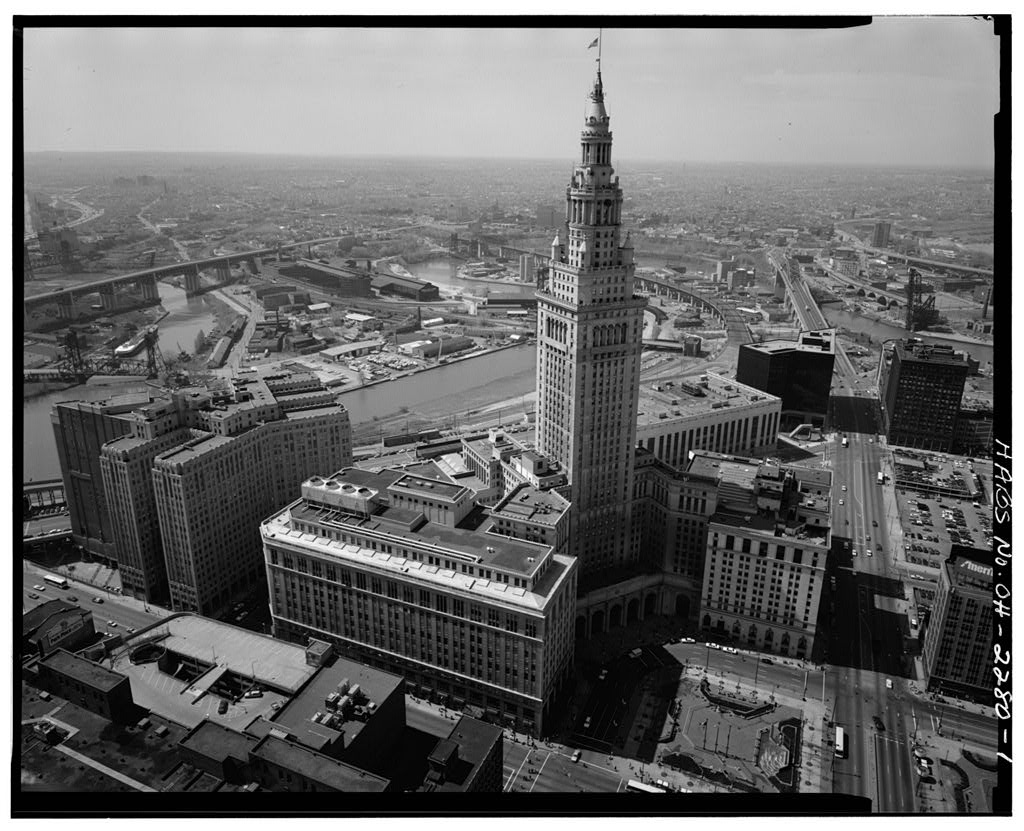
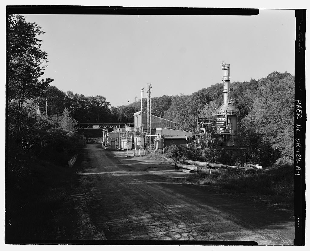
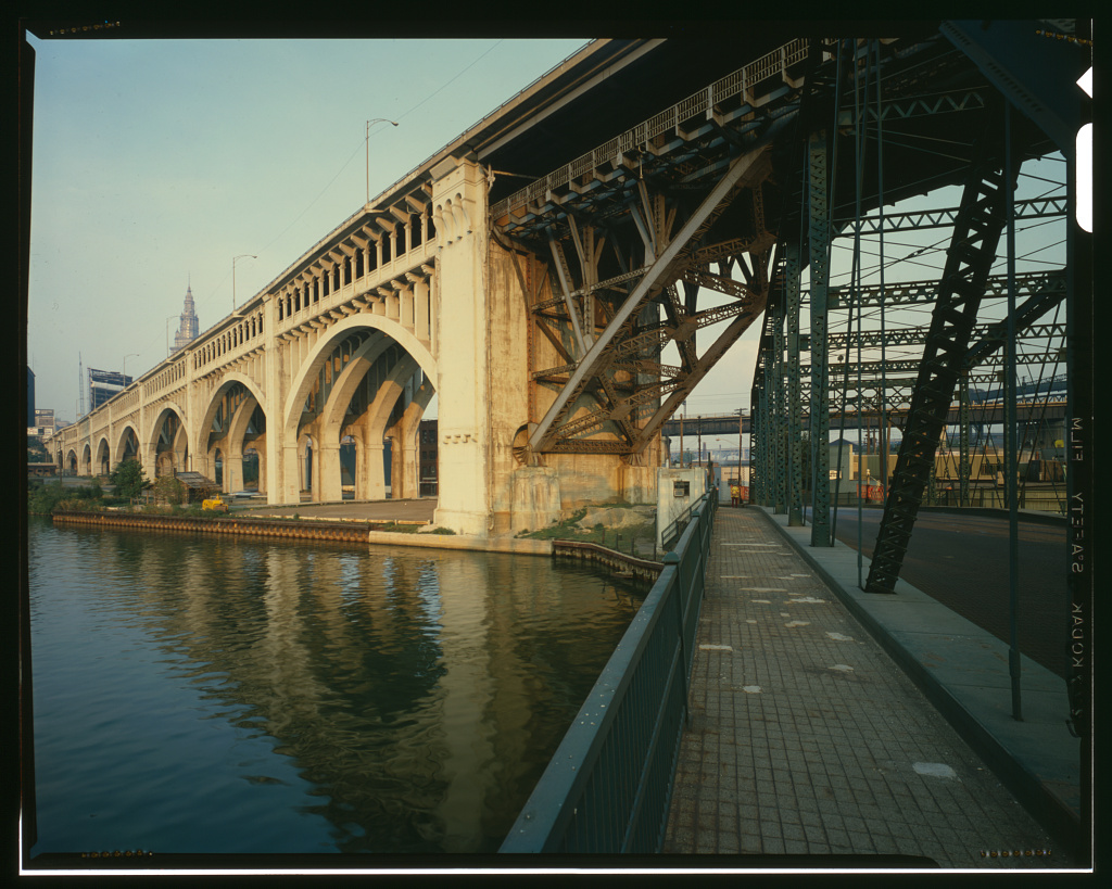
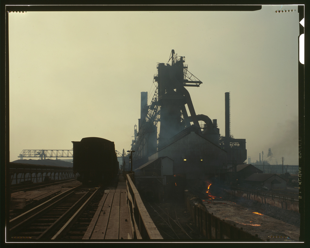
Division Avenue Pumping Station & Filtration Plant, West 45th Street and Division Avenue, Cleveland
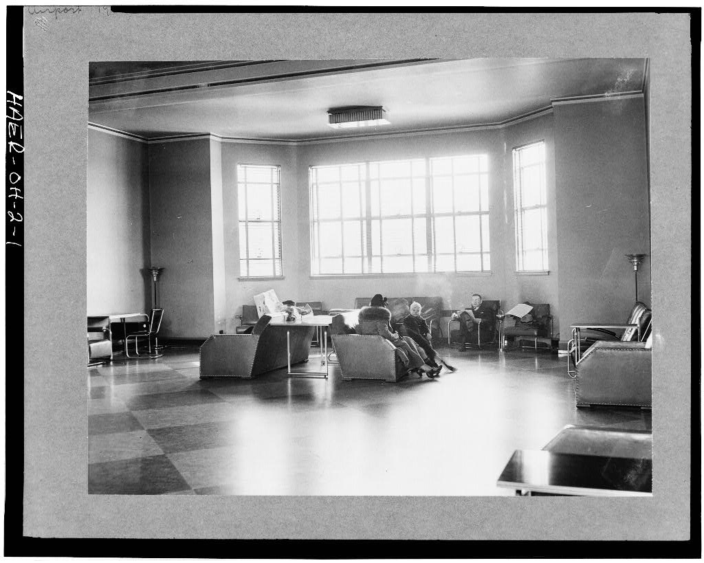
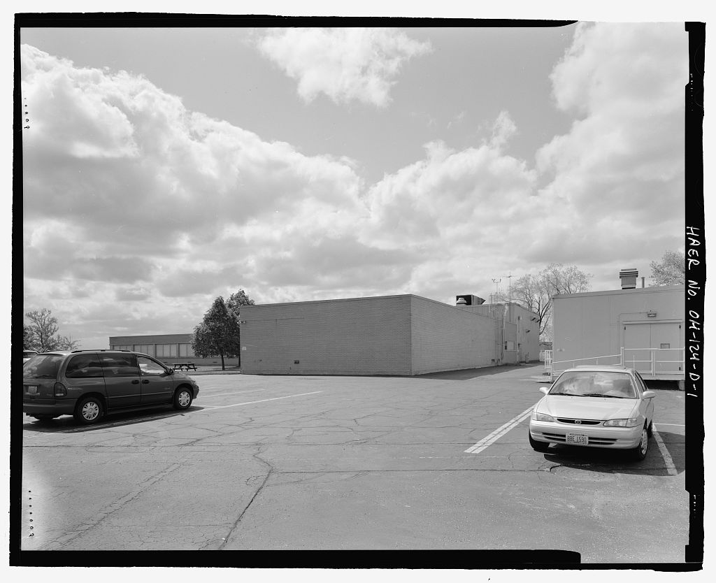
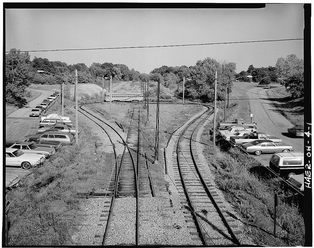
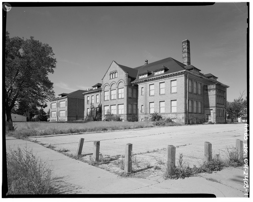
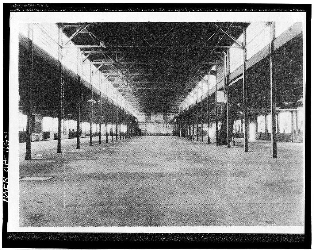
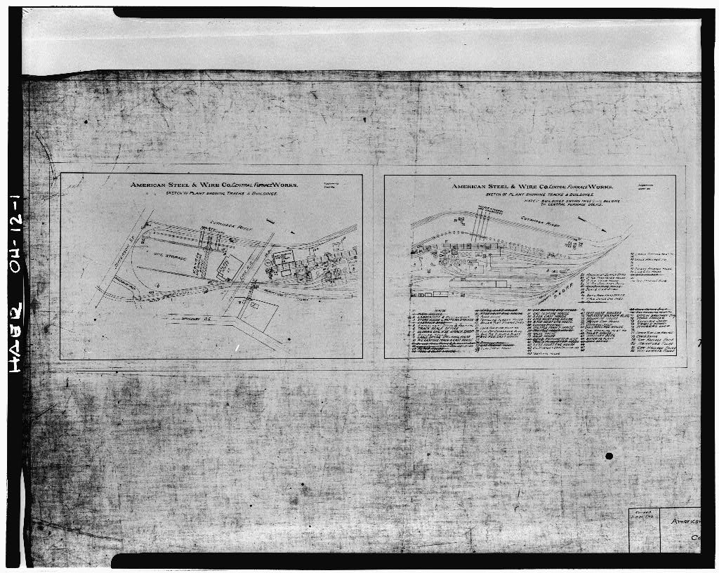
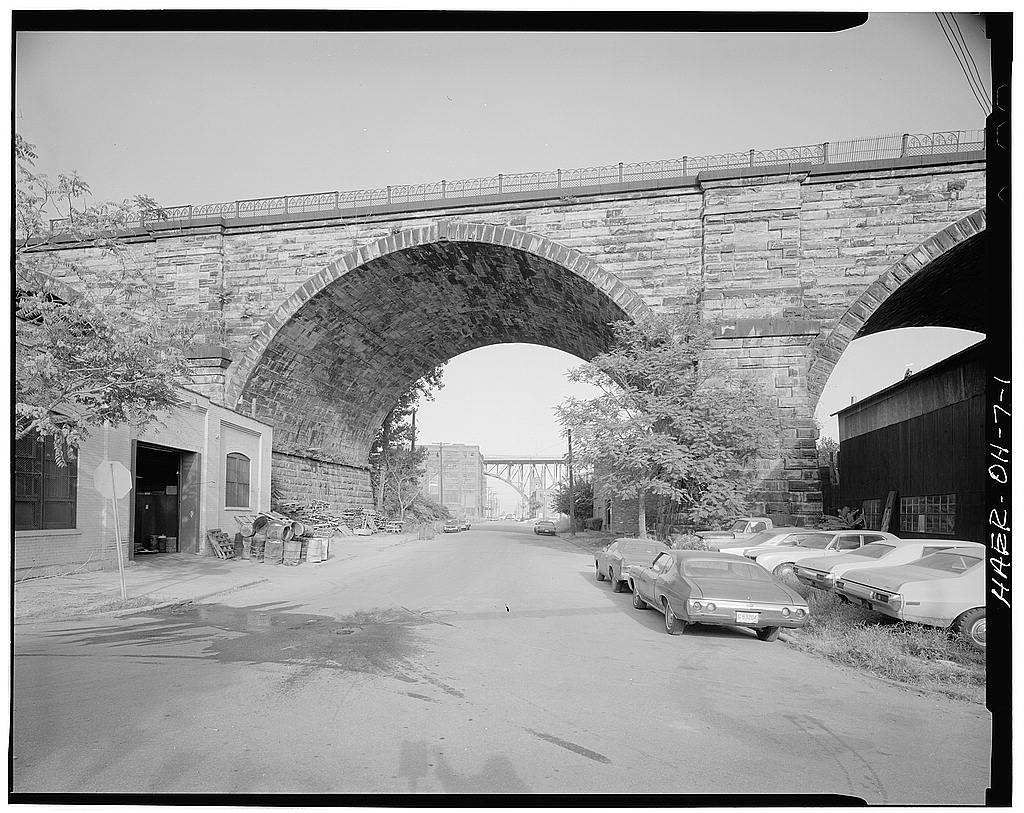
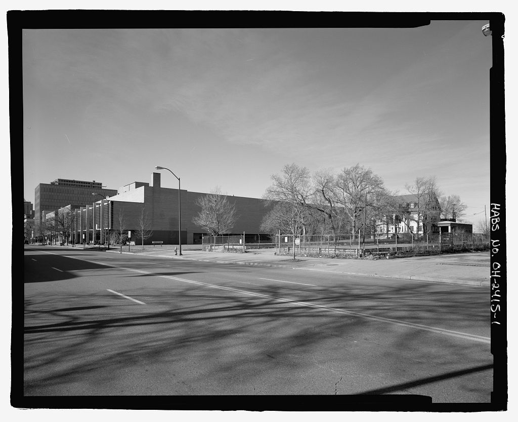
Division Avenue Pumping Station & Filtration Plant, West 45th Street and Division Avenue, Cleveland, Cuyahoga County, OH. Surveyed as HAER OHIO,18-CLEV,18-, with 1 photograph and a 24,038-word written history.
From the record
“Baldwin Filtration Plant City of Cleveland Division of Water Stokes Boulevard Cleveland, Ohio Herman Kreglius, Architect A.G.”
Written record, HAER OHIO,18-CLEV,18- survey. Machine-read text.
surveyed by the federal HAER program as HAER OHIO,18-CLEV,18- · the record runs 24038 words · one of 115 surveyed structures published for this county.
1 photograph from the federal survey record, Library of Congress.
Present Use
54 words
Source document
Quoted word for word from HAER OHIO,18-CLEV,18-.
Not written, edited or summarised by this site.
Water filtration and pumping S\261ngnificance: The two plants represented state-of-the-art technology for water treatment. With their additions over the years they have supplied sufficient clean water to the citizens of Cleveland. 'Ille ronstruction of the two plants evidenced several innovative m:,verrents in the history of technology as applied to tunnelin~~ the\267 treatment of water.
Written history
18031 words
The headings the report itself prints. Each one jumps to where it begins.
Source document
Quoted word for word from HAER OHIO,18-CLEV,18-.
Not written, edited or summarised by this site.
Ed Pershey, "With reference to Cleveland, the most prominent difficulty presenting itself to the citizens, is to obtain pure water near the city, unaffected by town drainage, and the discharges of the Cuyahoga Ri ver 11 2 Theodore" R. Scowden Water Works Engineer :,; . HAE!Z-oH-3 , /IA\247/2.-DH-3 This historical report on the Division Avenue Water Plant and the Baldwin Filtration Plant & Reservoir of the Cleveland Water Supply System rests formally on the sites themselves and the sources cited in the notes, but in reality owes its existence to the help and cooperation extended by numerous city officials, especially those of the Water Department.
John B, Nash, administrative officer in the water commissioner 1 s office, not only discussed the department at length but offered free use of historical material which he had collected and saved from the garbage heap over the years. Mr. Nash served as a liason with the rest of the department as well. Frances Bencin, in Utilities Engineering, made the search for and use of engineering drawings of the system a rel:atively painless procedure. Utilities Commissioner Louis Caris and Acting Public Utilities Commissioner Julius Ciaccia, although not directly involved in the day-to-day research work, were both highly accessible and cooperative in providing the necessary authorizations for use of material and access to the sites.
William Mucci, head of pumping, and his assitant Frank Brooks, who made the Division Avenue inspection a real learning experience, were not only cooperative but higflly sensitive to the HAER survey work. James Jerreris, head of filtration, was an inform\255 ative friend 't1hose tour of the Baldwin Plant brought that facility into unique perspective. Thanks go the Cindy Darwal, of the Commissioner 1 s office, who worked hard in coordinating the HAER work with the daily operations of the department. Special thanks must go to John Wolfs, of the Cuyahoga County Port Authority, whose long friendships with the water department personnel made the initia] contacts smooth and immediately fr'uitful.
As she had done for the whole summer recording project, Margaret ~larden, in charge of the Cleveland Picture Collection in the History section of the Cleveland Public\267 Library, bent over backwards to allow copyi\267ng of important photographs. The U.S. Army Corps of Engineers, who provided 80% of the funds for the wl~e summer project, also allowed the use of their boat to gain a close-range view of the water intake crib located 4 mile out on Lake Erie. This cooperation of the Water Department of the City of Cleve 1 and comes at a critical time for the water supply system.
The 1 ast of the city 1 s revenue-generating utilities, which provides water to the surrounding suburban cotntT!unities, the department, in has begun to be affected by the growing financial crisis of the city of Cleveland. Substantiala.,.mounts of the department's captial impr:-ove\255 ment fund are being borrowed by the city to meet general municipal operating expenses. Belt-tightening, a constant public service process, has in especially affected in the.\267water system which had been run in recent years in a short-sighted, penny-wise manner in a successful attempt to keep the Cleveland water rates some of the lowest in the country.
At the writing of this report, the city 1 s ability to repay the borrowed water funds and the transfer of the whole water system to a regional governing body are two questions only now being raised. The HAER study could not have come too soon. l 3 /..Jt/e'K - '3 I LAKER ERIE AS A
Water Supply
The City of Cleveland sits at the midpoint of a 40-mile long, 7-mile wide bay on the southern. shore of Lake Erie. The 1 ake holds over 100 tri11ion gallons of water.3 It is not surprising, then, to find that the development of the Cleveland v1ater supply system is essentially the star; of the city 1 s efforts to draw drinkable water from the lake. As with so much of technological-industrial Cleveland, Lak.e Erie has been the defining force in shaping the city iWhi ch reflects the potenti limitiation and parameters of nature1.s lake. Drinking water and general water supply for Cleveland did not always deri:ve from the lake.
Until the mid the main sources were spring wells located throughout what is now the downtown area.4 The first public well early in the century was dug on Bank Street near Superior Street (W. 6th Superior) and was eight feet across. How\255 ever, spring fed well water proved too hard (high mineral content) for use in ivashing, and there was a ready market for the watennen who haul- ed lake water to the citizens, charging by the barrel.5 In the City Council authorized the Supervisor of Streets to dig public wells . of 3 1/2 feet diameter as long as the cost per well was less than Larger scale efforts to provide a continuous supp.ly of water did not succeed.
In the Ohio Legislature incorporated the Cleveland Water Company, under a group headed by one Philo Scoville, whose charter required them to supply water to the citizens of Cleveland. Except for the collection of funds through the sale of stock, and in spite of a legislative amendment in the company .never materialized, no water ever delivered, and very little is known about the plans or the men behind it.7 In a group of investors promoted a real estate development on the east bank of the Cuyahoga River on Oxbow Bend, to the south and west of Public Square. Since even by then the river water was not suitable for drinking purposes, the investors devised a water delivery system; using as a source a spring on Wi1leyvi11e Hill west of the river.
The spring water was first collected in an artificial timber and brick well, then piped to a gallon reservior, and finally carried another 500 feet\267 in pipes to the river bank. Pipes laid under the river carried the water to Cleveland Center, the name of the new development. The system had a capacity of barrels (approx. gallons) per day. The water system disappeared with the rea 1 estate venture. 8 y a 1 , ~l!Jee-61-t - 3 By the early the City Council in Cleveland decided that a water system supplying the 1t1hole city from a dependable source more extensive than i ndivi dual we 11 s was needed to meet the needs of a city which had boomed in the 25 years following the operning of the Ohio Canal.
In a committee headed by Mayor vJi 11 i am Case was formed to study three possible sources: Shaker Mills, Tinker's Creek and Lake Erie.9 After some delays caused by surveyor's errors, the committee reported late in with these recommendations: 1) a reservi or in the form of a 1t1ater tower be erected near Euclid Street in the heart of the city to provide sjjfficient pressure for firefighting, which well springs could never provide; 2) a low service reservior for normal drinking and washing supply; 3) the reservoirs to be fed by pumping engines run by steam power (preferably Cornish design engines); 4) the work to be municipally built, owned and operated; 5) the water to be drawn from lake Erie; 6) and that the city hi re Theodore R.
Scowden watervJOrks engineer in Cincinnati, to\267 plan and supervise the construction. City Council adopted the report on March 22, That same yar the council also approved the sale of in bonds for the establishment of 14ater Works Trustees and the erection of the works.11 1-Jith the hiring of Scowden, and his first report in the municipal water v1orks of the City of Cleveland began to take shape. Although no part of the original installation remains,, and all but four engineering drawings have been 1 ost or destroyed vJi th very few photographs or engravings surviving, the design of the system was to determine the future development of the Cleveland 1.1ater system, and so deserves description.
A7lso, the site chosen by Scowden has been occupied by the water department continuously since that time, it being the site of the present D:i 1 Vi'Si6o Avenue Pumpinq Station and Filtration Plant.12 Scmvden prepared three different systems, one of which was adopted by the city council. The plan approved for final construction followed the recommendations of the committee of except that it abandoned the high level water tower on Euclid Street, even though Scm1den had origina.lly desi~nect\267it for one of the other plans substantial structure with "such embellishments" as ll vwuld give fine effect to the appearance of the Tov,er, and lend great attraction to the spot, as a place of public resort. 11 13: \\225Jhat apparently scuttled this tower 6.
I-Vf&t2- OH~;, was the annexation of Ohio City, on the west bank of the river, which was generally on a higher plateau than the city of Cleveland and afforded a site for a reserv\251j.r high enough toi obviate the need for a tower. The system approved by the council 1,11as to supply an area bounded by the 1 ake on the north, Erie Street ( E. on the east, the Cuyahoga River on the west, and Eagle Street on the south--a total area of about 1/3 square mile--using 11 miles of pi~es. A pumping station located near the shore of lake Erie, at the foot of Franklin Street, on the city's newly acquired \\267vest side, pumped \.'later from the lake to a high level reservoir, also on the new west side, just south of the station, from which the water would be gravity fed to the city.
The pumping statriton was eventually located at the foot of Kentucky Street (W. with the reservoir at the corner of Kentucky and Franklin Streets. Water from an inlet cri"b about 300 feet out into the lake traveled by aqueduct from the submerged pipe, around the \vest bend of the Old River bed, thence eastward to the pump house. The pumping engines, sucking the water out of a rising well, forced the water up to the reservo'ir.14 By drawing the 1;1ater from 300 feet off shore, Scowden felt that in regards to a supply of pure 111ater 11 the citzens have no occassi on to fear that the 1 ake water may ever be contaminated to a degree impairing its pure and healthful quality, at the point where the water flows into the aqueduct pipe for the supply of the pumps.
11 15 Scowden estimated that the completed system, designed to supply inhabitants, could easily supply a city of twice that popula.:: tion and with "an enlargement of the main pump barrel and plunger to each Cornish engine, which was comtemplated in the plans" the system would be able to serve the city for fifty _years.16 As far as the pumping engines themselves were concerned, Scowden's prediction came true, but the system as a 1.>1hole became outgrolALn within 15 years. Two major elements of Scowden's design, the pumping engines and the reser\255 voir, deserve description before we assign them to the historical junkyard.
The engines selected for the pumping were an English design called Cornish, because the type\267 had developed and been perfected in the Cornwall mining district in England for the drainage of mine shafts. They were parti cul arl y we 11 adapted to the purposes of pumping water. The Cleveland enqines were ordered from the New York Allair ~larks owned by Commodore Vanderbilt .17 Two engines were ordered, to be worked alternative weeks, so as to always have a duplicate, back- up pumping system. Total cost of the b10 engines, including construe\255 ti on, transpor.tation, on-site erection, furnaces and chil"meys came to The cylinders had a diameter of 70 inches and a 10-foot stroke. The beam was double and unequal, with arms of 15' 11 1 and 13' 11 1 /2 11 , and was 6 1 8 wide, wei 40 tons.
At nine strokes per minute (an average running speed) the engines attained 120 thouqh they were apparently worked slightly faster, and could generate ii 1-1AeK-ott ::3 up to 200 The pump plungers were 30 inches in diameter, and moving through a stroke of 8 1 9 11 raised 320 gallons of water per stroke to a height of 150 feet.19 A description how the engine worked was given in at which time they were still occassionally used: When steam is admitted above the piston, the space below it is placed in communication with the condenser when the preponderance. of pressure upon the upper side forces the piston downward, raising, by means of the 1AJalking beam, the plunger and the larger counterweight over it.
At the end of the up-stroke the steam admisston valve in the exhaust pipe leading to the condenser are closed, while the valve in a pipe connecting the upper and lower ends of the cylinder ppens, equalizing the pressure above and below the piston, which allows the counterweight to force the pl under downward and the water out through the disc!Jarge valve. A steam pressure of only 21 pound is used, but a vacuum of 26 1 /2 inches is usually obtained. The barrel of the steam cylinder is steam-jacketed. The valves are of the poppet type, operated by cams on a rockshaft, driven from the walking beam. The cut off on the steam valve and the closing of the exhaust valve may be adjusted independently by means of a screw connected v,ith the valve drivinq rod.
The condenser is of the jet type and the air and boiler feed pumps are both driven from the walking beam. The boiler feed pump draws water from the condenser discharge .20 The Cornish engines \AJere the first of their type built west of the Alleghenies and were the pride of the city as well as the water works.21 By however, the high level of efficiency of the engines has dropped, due to their age and a new system of more exact measurement of coal consumption.22 In increasing water consumption meant that either the two Cornish enoines must pump together, or that new engines be installed. In order to preserve the back-up safety design, new Duplex (double-acting) steam engines were ordered from the Cuyahoga Furnace Company of Cleveland.
After installation of these pumps, and another set of Worthington Duplexes in it became apparent that the new pumps so lowered the level of water in the suction well of the aqueduct intake from the lake, that the intake tubes of the old Cornish engines no longer reached completely below the water level, and could not operate efficiently, and at times of 1 ow v1ater con di ti ons not at a 11.
23 Thereafter the Cornish engines \"Jere used sparingly .24 In because space at the Division Avenue plant became valuable for the installation of newer equipment, the Cornish engines were 1-IAG'R.\267 o H- 3 moved to the new Fairmount pumping station on the east side.25 They were used intermi ttantly there, even though with reinstall a- tion and a cleaning they proved to work at a high level of efficiency, and with less vibration than had been the case at the west side station.
The boilers were outfitted with smoke prevent:ton devices, which also improved the engines' efficiency.26 They remained at Fairmount in good \'larking condition until when they just plain outlived their usefulness and, although still in good working order, were dismantled and became the property of the private contractor hired to do the work, who presumably junked them for their scrap value.27 The Cornish engines at the Kentucky Street station had been housed in an engine building of brick with stone caps, sills, and cornices.
The building meaured across the front, with a center two-story structure 46' c 55' and two wings each meauring 29 1/2 1 x 52 A stand pipe, 170 1 high, was topped with an observation lookout reached by spiral stairs.28 The new reservoir was 1 ocated south of the; pump house at Kent\255 and Franklin Streets in old Ohio City. The grounds covered acres, and the base of the reservoir itself covered four, measuring 332 x 466 1 Built of earthen embankments, and lined with an impervious clay puddle and hard-burnt brick laid in hydraulic mortar, the reservoir held gallons of water in two com\255 partrrents separated by an earthen wa 11.
The retaining and di vi ding walls sloped 1 3/4 to 1 on the inside, and 1 1/2 to 1 on the exterior; retaining wa 11 s measured at the base by 15' across at the top, while the dividing embankment was similarly 52' x The water depth was 20 feet, with the water level, when the reservior was full at an elevation of 150 feet above the lake. The bottom of the reservior was slightly over 112 feet above lake level. Raw water was fed into the reservoir through a 24 11 diameter pipe, and drawn out by two 20 11 diameter outlet pipes or an overflow pipe of the same size. The community received the water untreated in any way.29. On top of the reservoir walls an 8-foot gravel walk ran around the perimeter, with an iron lattice fence at the edge of the open water.
A stone walk leading from Franklin Street allowed public access to the reservoir wa which became a fashionable ace for social promenading (HAER photo).30 The needs of the city outgrew the ganon capacity by but the new Fai-rmount Reservoir was not opened unti 1 Beginning in that year all the water for the city was pumped to Fairmount, and the Kentucky Street Reservoir deactivated. It sat, full out unused, until when it was drained and used as a storage depot. By the 1 and was no 1 anger 1 is ted on the property of the city water works, and had been converted to a park. The spot, now labled 11 Fai'rview Park 11 contains public gardening space in 1 k p 1 The complete system opened in cost and served a population of ..
The average daily pumpage in has been listed as gallons, although either of the Cornish engines working at nine strokes per minute could have easily pumped over gallons in a 24-hour period. By 1869,.the needs of the city had begun to outgrow the gallon daily level~ although only a quarter to a third of the population actually received water from the sys tern. 32 By the Cerni sh engines had been pushed to their limit, pumping in June of that year, just before the installa\255 tion of ne~, enqines over 6 million qallons per day, more than the total capacity"of the Kentucky Street reservoir.33 But by the first lake tunnel had been opened, a new engine house built, and plans \267had been drawn for new reservoirs and additional supply mains.
With the opening of the intake tunnels, \vater was pumped directly into the system, the reservoir acting simply as a pressure equalizer and regualtor 11 f1oating 11 on the supply line.34 The Cleveland water works had been expanding vigorously since and this energe~ic growth, at times highly daring and enthusiastic, would las~ until . the opening of the Baldwin Filtration Plant and Reservoir ,n the mid On August 23, the first shovels of dirt turned over out of the hole that was to be the shaft of a 6600-foot tunnel under the lake bed which would bring water from over a mile out in the 1 ake to the Kentucky Street station. Before construction ended /2 years 1 ater,.
seven workmen died trying to 1 ay a brick and mortar 11 pipe 11 through the clay and sand under Erie's bottom, to form the water supply tunnel that still in supplies part of the water processed at the Division .A.venue Plant. . Che~ical tests of the purity of the water surrounding the first intake pipe 300 feet out had showed a marked increase in solid, sus\255 pended matter, but the residents of Cleveland in the years imme\255 diately following the Civil War needed only their tongues to know that the water was not right--it tasted of petroleum.35 The only way to avoid contamination of the drinking water by the discharges from the Cuyahoga River was to move the intake pipe out further into the lake, where the polluted river water could become sufficiently diluted by the purer lake water.
The. tunnel can actually be described as a hand-dug pipe, using the density of the clay mar the form, or hole, and brickwork as a system.of an~ular bracing. As built it was slightly elliptical, with a vertical diameter of 5 1/6 feet by a horizontal diameter of 5 feet. Since it has not been drained and inspected since the construction of the adjoining 10-foot tunnel in it is assumed to be in a state comparable to that when built. A lake shaft of 8-foot diameter, protected at the surface by a wooden, pentagonal crib, reached the tunnel at feet below average lake water level. A similar shaft on the shore met the tunnel at a depth of feet (the tunnel rising to prevent the flow of sand into the suction wells on shore).
The lake shaft from the bottom of the lake to the crib was actually a cast and boiler iron pipe, standing on end. Water f16wed into the shaft and into the tunnel over the top of the iron pipe, which was j' 4 1 4. lo -/.IAE :e. - off~ 3 left open nine feet below water. Two sections of iron shaft:rng, stored on the ci rb, could be set onto the top of the shaft, extend\255 ing it above the water line, acting, therefore, as an on'."'off gate for the supply of water to the tunnel.36 All excavation in the tunnel was by human hand, transported out on a small guage railroad. Each car held 20 cubic feet of earth or 400 bricks. Cars 1r,ere hauled up or down the shafts by steam driven elevators, and along the tunnels by mule or manpower.
The average daily completed tunnel section 1\2671.as just under 10' feet. A tin pipe channeled forced air for the workers into the tunnel .37 For a 140-foot section of the work, a moveable cast iron tube section, a shield, was pushed by hydraulic ram through clayey sand that threatened to fill in as fast as tt was excavated, before the retaining brickwork cou be 1 aid. For most of the feet, how\255 ever, the clay itse,lf provided sufficient stiffness to allow simple excavation and the laying of annualr brickwork to fonn the tunnel. At places where the tunnel curved, the facing of the bricks received a thin 1 ayer of hydraulic cement rnottar to promote the smooth f1 ow of water through these non-1 i near segments .
.38 Two of the deaths recorded as construction re 1 ated were the result of the explosion of natural gas in the tunnel. Pockets of gas in the sand and.clay under Erie's bottom continually plagued the crews. Three of the other four deaths were the drownings of me begin transported out to the intake crib. The 1 ast death occurred on the crib when a workman fractured his skull in a fall \267off the lattice work of the crib. These mis fortunes did not brand the work as a jinx, for the difficulty of tunneling under the lake was understood to be a risky venture.
In fact, the Board of Trustees of the Water Works praised the contractor, in their report on- the comp 1 eti on of the tunnel, for his 11 energy and determination to overcome all diffi\255 culty, and for the faithful, substantial and satisfactory manner in which he executed a work demandina at al 1 times the utmost care and watchfulness. 11 39 The tunnel could supply gatidhs of water per day (40 and this was far beyond the pumping capacity of even both the Cornish engines running at full speed. The Cuyahoga and Worthington Duplex engines were brought in to handle the increased water fl ow.
Much of the water needed to be pur.iped directly in the system , because of the small capacity of the old reservoir, and the Cornish engines could never have provided the volume or pressure required for this. New engine houses at the west side pumping station were built in and by which time the type of engines being installed were triple-expansion Holly and Allis behemoths. Reservoirs on the east side now served the city, the main reservoir, Fairmount, located high above the- level of downtown structure, built in remains an active part of the Cleveland v,ater system in serving as the raw water storage for the Baldwin Filtration Plant just to the south.
New engines and the old Cornish engines provided direct 1 d pumping from Fairmount Reservoir to low, first and second high service areas.40 By this time, the Cleveland system had begun to take shape as a series of plateaus of \1/ater delivery service. The land along the 1 ake, up to an elevation of 120 feet ( or 30 feet be low the head produced by the old Cornish engines) became the low service district, fed water either by gravity from the east side reservoirs or by direct pumping from the Division Avenue station (the station acquired the nal'l'E Division when the new east side facility, Fainnount, was opened in along the lakefront.
Land at e levati ans of 120 rto 250 feet became the first high service district, that at 250 to 500 feet the second, and eventually a third high district area developed in the suburbs where the elevations above lake level ranged from 500 to 810 feet. These high service districts received water from direct pumping or later from water towers. A good example of the often abrupt demarcation between service levels occurs at the Fadnnount-Baldwin site. The century open reservoir, Fairmount, is 1 ocated at the bottom of a steep incline, just to the\267 north (lakeside) of the Baldwin Filtration and Reservoir complex.
This incline is the border between the first high service and second high service plateaus, the two facilities occupying two distinct service levels.41 The system completed and in operation as of was composed of an \267enlarge Division Avenue Pumping Sta ti on, on the west side, a large reservoir on the east side fed by Division pumps (Fairmount Reservoir), a pumping station fed by this reservoir (Fairmount Pumping), and a smaller first highservice reservoir also on the east side.
The next twenty-five years were to see the development of two major facilities: a new Division Avenue Filtration and Pumping PJant on the same site as the nineteenth century installations dating back to and a completely new Baldwin Filtration Plant and Reservoir on the east side, above the old Fairmount Reservoir. The histories, of the two plants, although connected by other development in the system, run in different paths and time slots, with deviations of quite different character. The chronological arrangement of this report will split into two here, to consider first the Division Avenue site and then the Baldwin site.
Included in the first wi11 be a disaussion of the construction of the associated west side tunnels, and in the latter information about the Kirtland Street Pumping Station, the east side tunnel and lake intake cirb No. 3. !-/At/2.\267 OH\267 3
Division Avenue Pumping Station and Filtration Plant
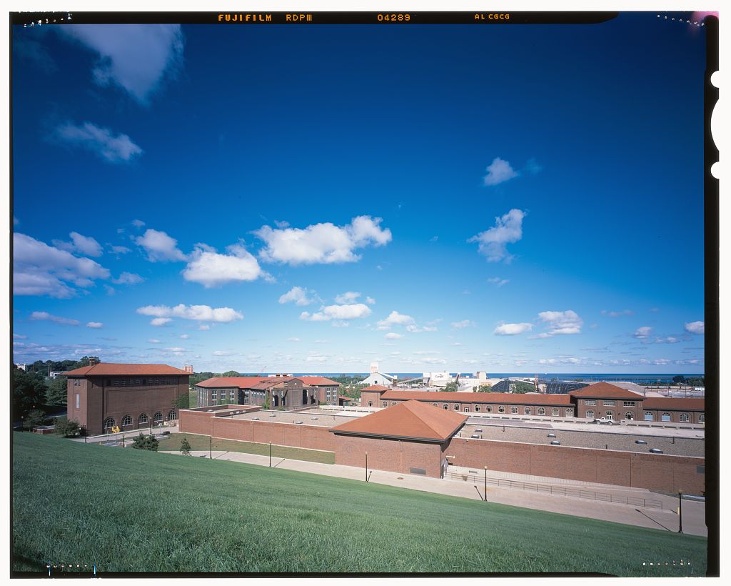
The Present facilities on Cleveland 1 s near west si:de shore\255 line, as the Division Avenue Pumping & Filtration Plant, date from the period on a site which has been occupied by the Cleveland 'tJater system since The pumping station built in conjunction with the extension of the west side tunnels (the original 5-foot and the 7-foot tunnel \'lhich also rant to the same lake intake crib) from their junction to a point feet further into the lake.
As completed in the Division Avenue Plant could pump, filter and deliver 150 into the Cleveland water system.42 Shortly after the turn of the century, the water at the intake crib serving the old Division Avenue Pumping Station became increas\255 ingly lower in quality, and as soon as the new 9-foot east side tunnel and the Kirtland Pumping Station on the east harbor shore- 1ine were ready, Division Avenue was shutdovm as a \.vater pumping station and the tunnelsdiscontinued as a water supply source. Water from the tunnels did get used in the steam enqines themselves which had been converted by Tom Johnson's Forest City Raih,ay into an electric generating station for streetcar operation.
The old Division Avenue facility served in this capacity probably until when the streetcar lines almalqamated into the Cleveland Railway Company.43 In plnas were being readied to extend the west side tunnels and enlarge the Division pumping capacity with a new engine house and additional engines of the huge triple-expansion type several of which had already been erected at Division, the new Kirtland east pumping station, and at Fairmount. Spring floods on the Cuyahoga River of that year affected the quality of the water supply so greatly that Mayor Newton D. Baker appointed a Filtration Commision to study the feasibility of adding a filtration plant to the proposed Division Avenue enlargement.
In the city had begun chlorinating the water at the Kirtland Station, which was, at the time, supplying the whole system with water. No filtering of the water done. Baker's five-member commission ran a series of tests on various filtering and water-softening processes in with the prior assumption that whatever process was selected would be some sort of mechanical filter device.44 A rapid sand filter experimental unit, of gallons per day capacity, was built for committee 1 s use. The water traveled through the unit in 2 1/2 hours, after being throughly mixed v1ith chemicals. The committee heavily endorsed the rapid. sand filter as the appropriate technology for any propo~ed filtration plant for Cleveland.45 Based on recommendation?
and with a growing typhoid death rate o~ly pa~t1ally solved by simple chlorination, the city added a large f1ltrat1on plant to the plans for the enlargement of Division Avenue. -OH The new pumping station, located partially on the site of the engine houses No. 1 & 3, and to the south of the original site of the engine house No. 1, rested on a foundation 16 feet deep within an outline of United States sheet steel piHng driven by steam hammer 30 feet down. Concrete' piles, inside the outline of the sheet piling, driven to bedrock, supported a 3-foot thick concrete matt under the engine mounts.
Three of the triple.\267expansion engines--one each of a Holly, Kilby and Allis--in place,in engine houses 2 and 3, remained at the location, and the new building 1,11as erected around them.46 The progressive architecture of the engine house matched that of the new filter building going up to the east of it. A special wire-cut, multi -shaded brick and dark mortar produced a 11 pl easing effect 11 that 1 asts to this day. The roof was trussed and covered with a fire-proof sheathing and red Spanish clay ti 1 e. Across the front the building measures feet 1 1Jith \vings of 151 feet (north) and (south). A boiler house winq on the east .. elevation measures 117 1 x 10³ 1 (approx.). Two chimneys of 9 feet internal diameter rose.
228 feet above the ground (,the top cornices have been removed, so they are somewhat shorter now).47 ancillary buildings were built in the same style and with similar material. Besides the leftover triple-expansion engines rebuilt onto the nei,-1 concrete matt, the engine house 11as equipped with three more nevi engines of the same design and three steam turbine centrifugal pumps, which li"fted the water our of the tunnel suction \vell and into the filtration ant. A fourth centri fuga 1 added in pumped directly into the first high service district.48 As it stands in amid weeds and crumbling staircases leading to former neighborhood streets, Division Avenue retains much of its classic air.
Although the last of the 6-story Allis-Chalmer triple\255 expansion pumping en1;ies became scrap in early the floor space once occupied by them contains how the 1 ow-profi ectri c centri fuga 1 pumps, sprawled across the floor. One Delaval steam turbine in operating condition rests in the north winq, used but still hooked up to the original Stirlinq boiler plant. Those boilers still in operating condition in are used sole1y for heating the buildinq. The dboiler house and the huqe boilars and-coal-stokers are due to be repla~e with a smaller structure and more-efficient heating furnace equipment. Huge wrenches and tools of a scale only applicable to a si~-story steam-breathing machine hang still on the walls of the engine house, as a reminder of past back-break-ing service calls.
s 2 p 1 1 e e 1 0 1-(AGil\267 oH 3 In the main engine room~ and the north wing, traveling cranes still play the airspace over the engine v1ells. Both Cleveland-Crane products, the main room has a crane of 25-ton capacity, and the l ow-'1 i ft pump room one of 10-ton capacity. The six original Stirling water tube boilers and the retort mechanical stokers sit quietly in the boiler house even today. Overhead, storaqe bins holdinq tons of coal feed the stokers by gravity, through automatic"weighinq hoppers' and are fed them\255 selves by two Link-Belt conveyors which double as an ash-removal system when not loading coal into the bins. Coal still fills the hoppers, and the mechanical stokers, run by water pressure, can still be used to feed coal into the furnaces.
The complete boiler house installation exists as built only there are no longer steam engines gasping,for the energetic vapor that is the boiler room 1 s sole product. As a heating plant, the boilers are mismatched to the function and face definite replacement with smaller furnaces designed to heat the building. The boiler room itself may became victim of the demise of the boilers, unless adaptive tise of the building can::: be justified. Economically it may prove easierto tear down the whole structure, than to remove the boilers and stokers pdiece- meal .49 A description of the pumping station, after the engines has been turning and pumping for over three years, realistically praised the new faci 1 i ty: After conditions in the station are not ideal.
If the station were rebuilt now, some changes would certainly be made, but.at the same time it is felt that it is a very efficient station, which will do good work for many years to come.SO The Filtration plant arose 'i'lith the new pumping station and just to the east of it. As with the engine house, the filtration building retains its architectural flavor, having been built in a style and with materials to match :its , neighbor buildings. In contrast to the pumping station, the filter building retains tts interior space and equipment much in the same form as bui 1 t. Few major changes have been made, and those that have, such as replacement of the roof, blend in very \'/ell i,.tith the original work.
Given the early history of Division Filtration, it is a complete wonder that it is extant at all, let alone daily filtering a large percentage of the Cleveland system 1 s drinkin9 water. ,6. OH Work on the fi 1 ter ant began in May of A large area to the east of the new pump station between the 01 d River Bed and Buckley Boulevard was excavated for the filter basins, the coagulat\255 ing basins and the mixing chambers.51 The excavation and the . pouring of concrete 1vas facilitated by two cableways spanning 730 feet across the site, stretching between four towers running on double railway tracks. This cableway, a major installation in itself, not only remo~ed dirt and brought in concrete, but moved other major equipment around the construction site.
A concrete mixing plant, erected on the site of the power house, supplied the 5-yard capacity buckets of the cab 1 eway vi conveyor be 1t and 3-'.'foot guage railroad. Electric lights along a smaller, third cableway allowed nighttime work. The walls of the basins were poured using reasable, interchangeable wooden forms produced on site. In one ten\267 hour period as much as cu. yd. of concrete were poured, and the maximum 'fi0r one 24-hour period being The large coagulating basins (where the impurities clumped together before filtering) measured x 250 1 andabout20' deep. The mixing chambers are The floor of the coagulating basin and the filtered water reservoir were poured as groined arches, inverted. The mixing chambers were flat-floored and baffled.
A brick building with clay tile roof covered the 36 rapid sand filters. This one-story filter building, 733 feet long and 50 feet 9 inches wide:,, had two wings with 18 filters in each, and a 75' x 75 1 (approx.) administration building in the center, which had two stories and contained offices and testing laboratories.53 Soon after completion of the construction, but before the plant was put into operation, serious problems began to arise that would delay the opening of the plant for almost two years. The new facility was said to present 11 the picture of a:\267remarkably extensive foundation failure 11 54 Settling as the ends of the long coagulat~ ing basins reached 6 11 to one foot during The plant had begun to fa 11 apart as soon as it was finished.
The cause of this major failure lay in the construction of the whole structure on a concrete slab which was 11 floatedll on the unstable clay and sand (quicksand) along the bah-ks of the Old River Bed. Although the. pumping station had been built on piles driven over 40 feet down to hard bedrock (necessary because of the huge weight of the engine), and although the U.S. Army Corps of Engineers had been building extensively along the lake bed for many years, and the water department itslef had tunne 1 ed th rough the layers in the area, --apparently in spite of much previous example and knowledge--the new filter installation did not rest on any foundation piles. The result was that the filtered water reservoir and the ..
coagulating basins were so cracked from settling that they were unusable. Once such basin, the most westerly coagulating basin, has never held water and remains unusued even today.55 Likewise, the effluent conduits leading from the filters had to be replaced by closed pipes which v1ere run through the original open conduits which were changed to simple dry access shafts for the pipes. p 1 a a !l,4ek\267 D!l When a section of roof of the west basin of the new gallon filtered water reservoir collaoosed on July 9, three consulting engineets (one Clevelander and two non-Clevelanders) formed an investigating committee in the v1ater departrrent. Their exaMination of the nature of the foundation floatino on layers of quicksand and peat led to considerable repair work over the eight years.
Immediately, one of the consultants, Johnston of Mew York, drew up ans for the re ni ng and rej acketi nq of the tota1 ly unus\255 able filtered water reservoir. This v.JOrk began\267 in early and finished before the year ended. Other 1.,11ork begun in included-' the removal of all backfill from the foundation of the west end of the filter oalleries, and the removal of the brick superstructrure of the filter buildino over that end. Holes \1ere cut throuoh the rein\255 forced concrete o{\267 the cracked effluent galleries, and pi- l es ( of steel pipe and concrete) were driven to bedrock and the foundation structure of the concrete galleHes rebuilt upon them.
As started before, the open effluent conduits were converted to dry causeways through vJhich a 48 11 steel pipe line in and the plant opened in with a wooden shed coverina the west end of the filter building. - In further reinforcement of the foundation using pi 1 es driven through holes in the oriqinal foundation, as in v1as completed. In the filter building section razed in was finally replaced, and sheet steel piling driven along the north, east, and west sides of the filter building to a depth of 5 feet into the stiff clay under the quicksand, was to prevent the whole structure from sliding into the river to the north.56 So far everything has held together. Settling problems \ 1 1ere not the only ones affecting the new facility. Plans to soften the water, as \,I/ell as chlorinate.
ammoniate and fi 1ter it, were subverted by the i nadeauacy and poor begin of the lime, handling equipmemt in the chemeical house. The mixing chambers, through which the water flowed and churned after the chemicals were added, and been designed with 144 baffles along its 650 foot length to promote mixinq. 1\267Jater v-1as to flow at a rate of 60 ft/min. It was found, however, that with all these baffles in place the water would hardly flow at all, and 108 of them were finally removed. ~Jith all the baffles in place working parameters could not be determined, but the final operating figures, with the remaining 36 baffles, showed a water movement at 20 ft/min and a of head (or pressure) of a respectable 3 feet.57 p 1 1 i $ / .
1-IAER- O!f-3 In its final forrn, Division Avenue Station and Filtration Plant processed water through a succession of operations: pumped up from the lake through the new 10-foot, and older 5 and 7 foot, tunnels, water entered a 30-foot diameter screen well \'/here 1 arge objects 1i11ei-e removed before the suction wells for the pumping engines. Running by gravity into the suction wells, the water was lifted into the filtration plant by the centrifugal pumps in the north wing of the engine house, flowing through a 72" riveted steel pipe into the chemical house. Chlorine, ammonia and alum were added to the raw lake water, which then flowed slow1y through the baffled mixing chambers. From there the, \'iater spent the next several hours in transit through the coagulating basins.
Here ir.ipurities settled to the bottom or rose to the top of form flocculus or 11 floc, 11 floating clumps of impurities catalyzed by the alum. Passinq through the sand filters, the sand and gravel removing the 11 floc, 11 the water became purified into-its final form, and flowed then into the filtered water reservoir. Of only gallon capacity, the reservoirv1as really the suction well for the hugh rotary-crack-piston\267 triple expansion engines that pamped-the\267water directly into the system.
A small portion of the water, gallons, remained at the plant in a wash-water reservoir, and could be forced backwards throuah the filters to cleanse them of the build~up of impurities.58 - Except for the substitution of electric centrifugal pumps for the steam driven turbine and rotary-piston pumps, the present operation at Division does not differ from the original sequence in any gni fi cant way. The final rehabilitation of Division in coincided with the completion and opening of the Baldwin Filtration Plant and Reservoir complex on the city 1 s east side, and marked the first year that all of Greater Cleve served by the 1~ater Department of the City of Cleveland received ch\:lorinated-fi ltered l:'Jater.
It also gave the system, for the fi.rst time, an east-west balanced, duplicate .syitem. The beginnings of Division 1 s east side mirror-image system rest with the construction. of the nine-foot diameter lake intake tunnel and intake crib Mo. 3 at the end of the nineteenth century. s i 1 and i +fA&R_-6H\2673 I II BALO~JIN FILTRATION PLANT &
Reservoir and the East Side Water Supply System
In the Cleveland water supply system was taking water from Lake Erie, at a point a little more than a mile from shore beyond the west harbor area, and pumping it directly, untreated in any way, to its west side residents, and also to the e\267ast sjde residents via the Fairmount Reservoir and re-pumping station, and the reservoir on Kinsman Road. The demands on this sys:tem were great, and the qua 1 ity of water at the al d intake crib had decreased greatly. That same year the east side lake tunnel and the Krit1and Street Pumping Station on the east harbor shore construction projects v1ere started, but not until did they begin supplying water to the citizens of Cleveland.
The new lake tunnel, 9 feet in diameter, ran from the east shore feet, at an angle, to a new intake crib about 4 miles directly opposi t the harbor entrance and mouth of the Cuyahoga .59 The ci rb, known as intake Crib No. 3, and the tunne 1 serve the v.tater system in Crib No. 3 is the sole remaining visible intake crib; all others have been converted to or bui 1t as submerged structuwes. Built in the crib sits in 50 feet of water, and rises almost as much above the \'later. The outside diameter of the steel well-like structure measures 100 feet vlith an internal well of 50 1 diameter. A two-story-plus-light-tmver structure rests on the crib, its floor about 20 feet above water level.
Originally manned by a tvw-person crew who operated warning and fog whistles, the crib works automatically now, and is home only for spiders carried over in earlier days. \\267later enters the lake shaft of the nine-foot tunnel throuah twelve inlets around the circumference of th~ crib, each 6 1 x 7 1 The ratio of inlet area to tunnel area was purposely kept high (8: 1) to keep the influx velocity low to prevent ice from being swept into and through the ports and clogging the inlets or tunnel itself.60 On a clear day the red-rimmed crib shows idearly from all along the Cleveland Shore, and is visible even in relatively poor weather. It serves as a fairly good indicator of air clarity.
The tunnel wfuich sucks the lake water through this intake presented a host of serious problems, taking almost with years to build. In fifteen workmen died in a single week in accidents around crib No. 3 and a temporary construction crib No. 2. 1 i C/ 1-/Aej_. OH\267 3 On August 14, the temporary crib along the line of the tunnel about feet from shore, caught fire and burned to within 13 11 of the 1vater. Burned to death vJere five workmen, another four drowned trying to escape, and still another man died in an attempt to save the others. A separate incident involved the pressurized tunnel entance. The tunne 1 had been pressurized to keep leakage into the unfinished brickwork at a minimum, and access shafts were provided with double pressure locks.
On August 20, such an access shaft at crib No. 3 broke off at the lake bottom and shot up into the crib, partially filling with water at the same time. Five men drowned in this single acci dent.61 The tunnel, a 3-concentric-ring structure, upon inspection in revealed a series of defective work, a result of the combination of contract price, time schedules and continual delays because of loose sand, clay and pockets of gas~ as had plagued west side tunnel construction. However, the nature of the poor work in the east side tunnel,made the previous work on the other side of town look like a masterpiece of supervision and handiwork.
The inspection revea 1 ed: 1) a section completely blocked by sand filling in the tunnel thtough the bri\267ckwork; 2) a 1 section very si\267riilar to that of the first; 3) 130 test holes to inspect the brickwork found that the third (outside) ring completely missing in placesj bricks had oeen simply tossed into place in other sections; and that in some areas none of the three rings were held together \vith mortar, but the bri simply shoved together; 4) of all this work, however, only 400 1 of one section lacking an outer ring of bricks needed complete replacement. These problems were compounded when the tunnel was deoressurized and san?
and gas began ~eepi~g in.62 The tunnel was not ready for use until from which time until the openina of the Division Plant in it carried the whole water supply for the city. A new pumping station, on the lake shore at the foot of Kirtland S~reet (E. ~,as ready t? use the, new tunnel in Equipped with tv,o Holly tr:p!e~expansi~n s~eam engines, the station'.s capacity equaled that of.D1v1s1on at tne ti~e (50 The station pumped raw lake water into the system unt,1T911, when in September chlorine H!feR - OH\267 3 of 1 ime was added to the 1vater to combat the bacteria in the water which had been causing typhoid deaths in Cleveland at an increasing rate, as the solid waste content of the lake water became areater as the Cuyahoga River became more polluted.
In Wallace & Tierman liquid chlorine machines were installed. Chlorine is still applied to the Cleveland water in liquid form in The water, however, in was not filtered rilor was there odor control of any kind.63 In after the opening of Kirtland pumping station, 30 acres of 1 and v1as acquired in the second high service district to the south and east, just above the older Fairmount reservoir and pumping station, for the establishment of a larqe reservoir to handle the incresed flow of water which the new-tunnel allowed.
Excavation began in the winter of with the removal of top\255 soi 1 11 by direct 1 abor, the sole purpose of which was to provide 1-1ork for the unemployed at that time 11 .64 Excavation through the underlying shale rock began on May 24, by a local excavation company under contract to the water department. The excavation work required the laying of a ballasted railroad with lb. rails, a 120-ton Bucyrus digger crane, capa\255 city dumper cars and 3 locomotives to haul equipment and rock. This initi~l digging, eKcept for.
the final trimming which had to be left for a later time since shale rock disintegrtftes when exposed to the air, was complete in In that same year a special consulting commission ts sued a report on the enlargement of the Cleveland water system that endorsed the reservoir site as also a suitable location for a second filtration plant, an east side counterpart to the newly opened Division Avenue Filtration. The east side filtration plant had been planned for the Kirtland Pumping Station, but the soil there was of the same sandy, insubstanttal character as at Division and promised the same problems of settling and expensive foundation work.66 The reservoir site on Baldwin road offered a solid-rock foundation, and a reservoir-filtra\255 tion comple)I.
which was nearly as ideal as a pumping station-filtration combination. The old Fairmount re-pumping station was just to the north and could be revamped. In with the basic ho\267le for the reservoir dug, the construc\255 tion facilities were altered to include an 11 acre filtration plant with the 13 acre covered reservoir. A construction plant similar to that used at Divis,ion spanned the Baldwin site in the early 20 1 s. A single Ledgen'iood cableway v.Jith electric motors, running on a five\255 rail track on either side, carried cu. yd. bottom dump concrete bucket, and was controlled by one operator. The concrete mixing plant was just north of the proposed coagulating basins. A temporary a 7 1-/,L/e'R.
- OH\267 3 service railroad allowed the contractor to supply and service both the cableway and mixing plant.67 The pouring of concrete, the building of the filters, coagulating basins, mixing basins and conduits went without problems, and the whole complex was finished and put into full operation in October, The design of the filter building at Baldwin is similar to that at Division. An administration building is flanked by two wings to filter galleries, and is a skeletion steel structure with brick facing and stone veneer, with a graduate slate roof. A stone double stai leading to the main entrance covers the pump room for the fi 1 ter wash-water apparatus. The wash-water tanks are on the upper floor of the building, on steel grillage, and have a capacity of ga 11 ons.
The sections of the building covering the filters themselves are reinforced concrete with stone veneer. The roof over the center gallery between the two rows of filters is supported by a steel turss, but the roof directly over the filters in lower, a concrete slab on a concrete beam. The exterior roof is also graduates slate. An exterior walkway around the filter building rest on top of the concrete slab roof over the filters, at the level of the upper story of the administration building, with walk-through porticos halfway along the length of the gallery wings.
The fTow of water throu~h the chemical house, coagulating basins and fi 1 ters to the filtered water reservoir is basically the same as that of Divisfon, except that the old Fairmount reservori,r now serves only as a holding tank of raw lake water for the filtration plant, and the chlorination of the water at Kirtland station was stopped. Branch rnai ns 1 eadi ng off the pipes from Kirtland to Fairmount were sealed closed, and ra\v lake water once more crossed Cleveland's east side.68 Alum, the coagulant, was added to the rae water at the chemical _ house and mixed through the turbulence of hydraulic jump mixing flumes located in the same bui 1 ding.
From there the \~ater spent about 4 hours and 40 minutes makina its 1,vay through the coagulating basins just to the south of the main reservior. These basins, 1sJith a capacity of over gallons and average depth of about 15 feet, measure 110 1 x 662 1 (approx.). Here the impurities in the water clump together to increase the efficiency of the filter\255 ing system. ,P J../A13R -Ofl\267 3 The sand filters measure 1 x: 49 1 (interior) with an area of sq. ft. The sand and gravel material lay in the filter in five layers: 4 of graded gravel (22 11 total) and a 30 11 layer of sand. Water runs down onto the filters from 2 1/2 cast iron pipe with 11 diameter holes spaced on 4 1/4 11 centers.
The same process and equipment serves to treat Cl eve 1 and' s drink\255 ing water in From the filters the water flows via concrete conduits into either or both of the two halves of the massive fi1 tered water reservoi Two parts of the Baldwin facility differed markedly from Division: the size of the filtered water reservoir and the method of mi"xincr1 chemicals into the raw 1 ake v,ater. - Baldwin reservoir, when built, wa.s the largest covered reservoir in the world. measuring 100 1 x 521 1 (interior), with a depth of 36 1 A di vi ding \I/a 11 actua 1ly separates the structure into two independent reservoirs, 504 1 x 521 1 each ..
The concrete roof of groined arches rests on cl urnns, each 30 11 in diameter, 34 1 3 11 tall called an archi tectura 1 masterpiece because of the sense of space 1t1hi ch was created by the forest of columns and groined arches. Likened to a Gothic church by those v,ho were priveledged to view it before the waters fl coded into it in the reservoir conveyed a sense of "simplicity and purity 11 while at the same time it existed as an abstraction: It is the work of a law, of a formula ruling over space and mass--rather, perha~s a law brought into the range of our feelinqs\267 by being stated in the most fundamental 1 most simple terms of human need for formal perfection.
It is the product of man's desire 1ior order freed from the conventi ans of architecture by the new conventions of engineering. 71 This hall of columns holds 135,000,000gallons of filtered water to this day, and is s ti 11 the major fi I tered i,,1a ter reservoir in the Cleveland system, serving the low level service district (including downtown Cleveland) by gravity only, and the high service areas through the Fairmount repumping station, which was built in alongside the old station.
o 1 d -' 1 ,Pr 1-!AzR - OH - 3 Aside from Baldwin's impressive appearance, and the obvious quality of concrete i<1ork, although some cosmetic and a little structural deterioration is present (especially on the exterior of the che1:1ical house), the most interestina asoect of BaldvJin are the mixing chambers of a desiqn devises and patented by Joseph Ellms, engineer in the Cleveland water system. Called hydraulic jumps, or hydraulic mixing flumes, these visible sections of purposefully turbulent water in the chemical house across the main reservoir from the filter building, are the most innovative part of Baldwin Filtration. In his patent for an "Apparatus for Hater Purification" Joseph E11ms defined a hydraulic jump: ...
when a sheet of rapidly moving water strikes a body of 1t1ater vihich is either standing still or moving with a lovver velocity, the kinetic energy of the miving stream is very largely dissipated in the form of countless eddies and 1,,1hirlooo1s accompanied by the entrainment of large quantities of air seethe and bubble to the surface, the standing water being also elevated just below the point of impact to a height above the level of either the inrushing or the outflowing stream.72 Ellm 1 s patent covered, in essence, a naturally occuring phenomenon of one body of water running, tnto aridlthe.r.
In most cases~ in irrigation canals or at the base of water falls, such jumps of turbu\255 lent water simply dissipate the kinetic energy of the water and produced only sources of \vater flow problems. Ellms determined that such energy might be put to qood use in mixinq chemicals into water. His patent, is reality, covered the controlled production of such jumps through the use of inclined planes and the application of these jumps to mixing.
The hydraulic jump not only mixes through turbulence, but also aerates the water, eliminates the need for baffled chambers, and mixes small amounts of chemicals into large volumes of water ve ry 1t1e 11 Prior to installation at Baldwin, a large scale experimental mixing flume was set up at Kirtland Pumping Station w"1ere the characteristics of the jump for mixing and the appicability to large filtration plants were recorded.74 As installed at Baldwin Filtration chemical house, vrnter enters the hydraulic jumps from a rising well which lifts the water 28 feet to a large horizontal pool 70 feet across. This pool leads to three exp anding flumes where the jump occurs. The entrance to these flumes have curved entrances (abuttments of 5' radius).
The throat of each jump is 10 feet wide and 11 1 1 11 long, expanding to a 22' width and dropping 3 feet within a lateral distance of another . 7 3 H/.iGK- OH- 3 10 feet. The jump is produced along, near the base of, the drop. The v,ater enters into another 70 1 v,i'de common flume, which converges to 30 1 in a distance of 58 feet. A straight, level flume of 30 1 width, divided into a 19 1 wide conduit. Here, in the divided flume, are the v,eir planks which control the elevation of the \'later in the converging f1ume back at the base of the expanding flumes, and so controlling, ultimately, the location of the hydraulic jump (See HAER ). The conduit leads to the\267 coagulation basins.
This design was based directly on the experiments performed at Kirtland Pumping Station.75 The jumps are visitile from an operating gallery (see HAER and in the chemical house, and in fact must be visible to allow regulation of the location of the jump along the flume. As completed in the Baldwin complex cost the city of Cleveland (not\267including land and landscaping) a total of almost The experimental equipment at Ktrtland in the design investiga\255 tions for the hydraulic jumps did not represent the system's only experimental venture. In the years to both at Division and at Baldwin filtration plants, large scale water treatment experiments were con.ducted on, pri nci pally, the control of odors through dechlorination and ammoniation.
In at both filtration plants, ammonia in liquid form was introduced, directly into the viater supply to test its effect as a taste-and-bacterial-control agent when combined with chlorina\255 tion of the water, a process in use since in Cleveland. At Division the ammonia was added to the filtered water just before the chlorine, at a rate of 2 per million gallons of water for the first six months. After that, the dosaqe of arnmoni a dropped to 1 lb. per million gallons. At the same time, 3 to 4 of chlorine was being added to the same amount of water. The Baldwin exoerirnents varied conditions more often durina the test run, adding ammonia in the amounts of 0.5 to 2 pe; million gallons, and 2 to 5 of chlorine.
During the months April, June and October of no ammonia was added as a control test period. The results of the tests became available in early The ammonia successfully controlled the chlorine and other tastes in the 1vater, and sterilization was quick and highly satisfactory. Chlorine, at a solution of 0.1 parts per million in the water was found to prevent bacterial and gae aftergrowth and the addition of ammonia aa a taste control had no effect on the anti-bacterial action of the chlorine.
The introduction of ammonia increased the treatment cost per million gallons of water from to a significant increase of which prohibited wide scale use of ammonia in the system.76 a 1 l-t4E.R-OH-3 In and at Baldwin, more tests v,ere runn on odor control testing this time two possibilities: ammonta (again) and granular activated carbon. Over samples vJere collected in tests involving ga~lons of water. Three large wooden tanks with interconnecting pipes and valves, and Wallace and Tierman chlorinators, allowed a wide ranqe of flow parameters in the tests which focused mainly on the suitability of a 24 11 tile carbon fflter.
The tests were run on a large unit allow\255 ing 24-hour operation, and complete simulation of conditions at ei:ther Baldwin or Division or even parallel tests simulating both.77 The wooden vats and some associated va 1 vi nq and piping res ts still in the lower floor of the Bald\.\/in administration building. The tests on activated carbon proved fruitful, and this the material used today, especially in the hot summer months to control odors in the lake water originating from the higher algae counts. Next to the introd~ction of new chemicals into the drinking water, and the installation of new pumps., tunnels, reservoirs, filters and water mains, the most dramatic change in the Cleveland water system undoubtably occured in the years-1901-1909.
Daily water usage per capita had increased in the decade from 8 to gallons-an increase of The reasons for this i"iere an increase in household water usage and the fact the less that 5% of the users of the water v1ere being metered. A fl at rate of charge, independent of amount of water consumed, was applied to all residential users and most large commerical users. In the city began install\255 ing meter and chargi nq the consumer by the actual amount of water consumed, in all residential and commerical hood-ups. This resulted in a decrease in the daily per capita v1ater consumption in the first decade of the twentieth century from to gallons--below the level.
This represented a drop of Total consumption actually decreased as the rate of decrease in the viater usaae exceeded, the rate of increase in population and industrial growth combined. This ten year period of negative growth in the water system was reflected on a delayed basis in the building program, during the years to between the completion of the Kirtlam:1-9 foot tunnel and the start of construction on Division. The savings to the system v1ere substantial. Metering costs to the end of reached but i>Jere justified against the cost of additional faci 1 i ti es 1tvhi ch would have been needed-given the same rate of increase in usage experienced at the end of the century.
The real savings were estimated at about over the ten year period, though considering the grov,th of the system after this period, in even vlith a metered system, this estima:te aopears to have been highly conservative.78 W'{E:R - Ot-l\267 IV SUMMARY The Baldwin and Division Plants represent expansion of the Cleveland water system after the introduction of water meters, and after the readjustment of the negative growth rate of the decade The technology of the two plants, especially the filter- ; ng and reservoir sys terns, was such that the existing facilities have resisted major changes.
Even considering the structural instability of Division, the two plants exist and operate today much as they did in and The pumping station at Division remains architecturally the same as when it was first put into operation, but all steam powered pumps have been replaced on the lines by electrically powered centrifugal turbines.79 The new pumps are cheaper and easier maintain and run (relatively and actually), though they also create a dependence on the electric utility which had never been the case when the station produced its own pwoer directly from the burning of coal. The nre pumps also disrupt the scale of the old engine house.
At best reaching ha 1 f-way up the bottom of the fl oar we 11 s of the engines, the new pumps leave the several story engine room air space as a disturbing vacumm of form that seems to demand that something bulky ought to be taking all up that room. Eventually, this discontinuity of space in the old building will suggest its replacement, as at Kirtland, with a new, low-profile pump facility designed specifically for the newer pumps. Such a replacement has already been recommended for the boiler room Ning. All of Division may be scheduled for replacement if and when the city of Cleveland solves its financial problems or when the water system gets transferred to a regional governmental body.
BaldvJin, because of its excellent operating condition, will serve the system easily for another 25 years. The eventually future of these facilities, as historical sites, presents an intriguing value judgement for the historian and/or preservationist. Although both represent state-of-the-art water treat\255 ment tech no 1 ogy for their respective ti me periods, and architecturally classic brick and stone public works projects, and even though Baldwin has several important features which are innovative, they are both, nevertheless, crucial elements of a system of which the sole purpose must be to supply the citizens of Greater Cleveland with clean and potable water.
Should the replacement of either site be questioned, the ultinate answer rests on the system's physical ability to supply water. The engine house at Division Avenue is already a Cleveland landmark. Whether the other structures at Division Avenue and Baldwin Fairmount ought to be nominated as Nati anal Landmarks can only be o 1 d Ot-1. -:5 answered by the same value-charged consideration: how can the water sys:tem best perform its function, the supply of water. The historical important of both sites rests solely on their function of water treatrrent for the people. If they can fulfill that function in any way, either by continued service or through surrender to the wrecking ball, then that, in the end, ought to be the guideline whereby their futures are determined. l. 2. 3. 4. 5. 6. 7. 8.
9.
R.-Oh- Notes
Thomas J. Brazaitis, "Cleveland on the Brink.: Time, Political Tides tlndermine Water System,U Cleveland Plain Dealer, August 1, pp. 8A. Theodore Scowden, Report to the Common Counci 1 of the City of Cleveland, on the Subject of Water Works, for Supplyin~ Pure and Wholesome Water to the Inabitants, accompanied wit~ General Pl ans for Carrying the Project into Practice; together with a . Supplementary Report Suqgesti ve of a Thorough System of Sewerage in Connection with Water Works, C1eveliand: Gray & Spear, Plain Dealer Office, p. 5. Cleveland Water S~stem~ (City of Cleveland, p. 4, estimated that the lake hel million gallons. The Cleveland Water Story (City of Cleveland, )estimated billion.
The point being made in either <?ase was that a practically inexhaust\255 ible supply of water lay at Cleveland's doorstep. Cleve~and Water System pp. Benhu Johnson, a veteran of the,,war of supplied water from the lake at a charge of per two barrels. James Kennedy, A History of the City of Cleveland: Its Settlement, Rise and Proaress (Cleveland: The Imperial Press, p. I bi d. , p. 2 75 . Ibid., J. Whitelaw "The Cleveland Water Supply," Enoineering News : p. 132 ." The amen drae:nt gave the company the exclusive right to supply water for the whole city. Capital stock was allowed to increase to but only was \267rasied Officers were elected on May 4, and the company disappeared shortly thereafter. vJilliam G. Rose, Cleveland: The Making of a City (Cleveland: World Publishing, pp. p.
Kennedy, pp. 10 Hh i tel aw , 32 11 . Kennedy, p. 6 ( p l ;>( ~Hi4e12-Cl-l-3 12. In an execl!.ltive order of the commissioner required that a 11 uti ti es offices ean their fi 1 es for future growth and adequate record keeping. At that time all engineering drawings of temorary construction facilities and non-existant or obsolete sites and equipment were pulled from the files and destroyed. Four drawings from the ni neteeth century escaped the process. Two, of the Cornish pumping engines of hand today under glass in the office of the head of pumping for the vrnter depart\255 ment.
Two, of the original city reservoir, have been given to the Wes tern Reserve His tori ca 1 Society in No attempt was made to contact the historical society in regard to the drawing, although a large collection of photographic negatives was donated at the time to the historical society. 1 3. Scowden ( l 85 , 14. Wh i te 1 aw, p. 1 32. 15. Scowden p. 5. 16. Theodore Scowden, 11 Engi neer 1 s Report upon the CtJaracter, Capacity and Cost of. Cleveland Waters \fork,1' Report of the Trustees of Works to the City Counci 1 of the City of Cleve 1 and for the Year (Cleveland, p. 13. . . 17. 11 An Accident to. a Faithful Servant, 11 Engineering Record42 The drawings of the engine, on the back, 1 is t the same of Frederick Saunders as the engineer in charg\267e at the Allaire WOrks. 18.
Theodore Scowden, Third Report to the Trustees of Water Works of the Ci:ty of Cleveland (Cleveland, p. 6. 19. Scowden, "Engineer's Report 11 p. 10. The engine weighed about 200 tons each. 20. 11 An accident to a Faithful Servant," p. This information had been supplied to the Engineering Record by i~.~J. Kingsley, Superintendent of the C1 eve 1 and Water ~Jorks. 21. Scowden, 11 Engineer 1 s Report 11 pp. 22. "Report of the Superintendent and Engineer,' 1 Report of the Trustees of i~ater vJorks to the City Council of the City of Cleveland for the Year (Cleveland, pp. Same complaint was reported in the next year's report, 7. 23. Ibid.; for the Year pp. 2, 19; ... for the Year p. 9. 1 i c 1 3 ) p 1 4 t-fAER~rQH-3 24. Whitelaw, pp.
gives comparative performance data for Cornish and Duplex engines. The major difference seemed to lay in the amount of coal consumed in getting up steam in the Cornish engines. 25. 11 Report of the Superintendent and Engineer, 11 for the Year (Cleveland, p. 39. 26. Ibid., ... for the Year (Cl~veland, pp. 27. Schulz, 11 The Development of the Water System of Cleveland''.~' Journal of the Cleveland Engineering Society 9 p. 28. Scowden ( p. 7. 29. Scowden p. 11; Report of the Trustees p. 11. 30. Rose, p. has a full view of residents climbing the stairs and \'la 1 king on the reservoir wa 1 kway. 31. Annual Report of the Water 1forks Department for the Year p. 22; Annual Report ... p. 25; Annual Report p.
10; Howell Wright, 11 Cleveland 1 s Water Supply ProblemJI, Cleveland Engineering\26720 11 p. 4. 32. Schulz, p. Cleveland \fater System p. 5; E.E. Buchanan & Joseph if. Ell ms, 11 A Brief History of the Oevel and Water Supply", Cleveland \~ater Department, p. 1. (Typewri,tten.) 33. Report of the Board of Trustees ... for the Year p. 17. 34. Christman, 11 The Division Pumping Station at Cleveland Ohio and Its Opera ti onu, Journal of the American ~later Works Association 8 p. 35. e.eport of the Board of Trustees ... op. Whitelaw, pp. As late as lake Erie water was praised for its qualHy when unpolluted by the river. Joseph\</.
Ellms, "The Prob,lem of Hater Purification and Sewage Disposal on the Great Lakes 11 , American Association for the ,11,dvancement of Science, paper presented at Cleveland meeting, December 29, 36. Report of the Board of Trustee ... pp. 25, 27. 37. Ibid., p. 33. 38. Ibid., pp. 32. :;;,,ef_ 3; ~H- _3 39 bi d. 36 . 40. Schulz, pp. Buchanan & Ellms. p. 1. 41. Cleveland 1 s Munici allv Owned Public Utilities: Water Su , Sewa e Di soosal, E ectr, c Li ht and Power City of Cleveland, , p. 2, and The Cleveland Water Story center two pages, n. p. 42. Schulz, p. 43. Ibid., p. 44. Hippil>lyte Gruener, 11 Water Filtration and Softening Tests at t:>le:veland, Ohio 11 , Enoineering News 72 p.
Gruener, professor of chemistry at Western Reserve University, Cleveland, was a member of the Filtration Committee. Also on the commfttee were A.W. Smith, professor of chemistry, Case School of Applied Science, Cleveland; R. Winthrop Pratt, consulting engineer, Cleveland; Dr. Willaitn Miller, Ohio State Board of Health; and Perkins, City Bacteriogist and professor of hygiene and preventive medicine, Western Reserve Medical School, Cleveland. 45. Ibid., p, A 11 rapi.d 11 sa\267nd filter as opposed to a 11 slow 11 sand filter simply refers to the length of time the water is detained in the filter. 46. 11 Constructii,6n Plant for Cleveland Filters''., Engineering ,Record 70 Simmennacher, 11 Progress in Pumps and Pumping Station", Journal of the American Water \A/arks Association 35 p.
drawing 11 Water Flow Diagram for West Side 'funnels, Division Pumping Station and Filtration Plant 11 , Utilities Engineer- ing, City of Cleveland (HAER ); Cleveland 1~ater System p. 7; Schulz, p. Christman, p. A collection of 8 1 x 10 11 glass photographic negatives of the Cl eveJand Water Department dating principally. - contains a comp.lete photographic record of the construction sites at Division Avenue and at the later Baldwin site. This collection of approximately negatives, given to the ~lestern Reserve Historical Soceity in has only a cursory index and is, therefore still very unwi edly for research purposes. All the negatives however have sequential numbers, and some have dates and 1 egerlds.
The collection is an invaluable source for information on the construc\255 tion of 1 arge pub 1 i c works projects in ea r1y century America. . I , p . - 3 47. 11 Cleveland v4ater Supply to be Purified and Softened", Engineerino News 76 Schulz, p. The dimensions were altered slightly from an earlier plan vvhich called for shape 226 1 x 73' with a single wing 148 1 x 52 1 and boiler house 1neaur\255 ing c Christman, p. 48. Christman, p. Simmermacher, p. Schulz, p. The three o1'aer engines were triple-expansion rotary-crank\255 piston varieties, and had cost the following: Holloy - Kilby - Allis-Chalmers engines cost and 49. Schulz, p. Christman, p. 50 . Ch ri s tma 441 51.
Drawing 11 Filtration Plant at Division Pumping Station 11 , Utilities Engineering, City of Cleveland (HAER ) gives an excellent schematic of the site with construction apparatus. 52. 11 Construction Plant for Cleveland Filters'\ pp. 53. 11 Cleveland Water Supply to be Purified and Softened", p. drawing (HAER ). 54. 11 seri ous Settlement Destro11s Part of New Filter Pl ant 11 , Engfoeeri ng News 76 p. 55. Ibid., Greater Cl eve 1 and 1~ater Supply System Deve 1 opment Pl a.!1 Urban System Engineering Demonstration Grant, HUD Contract Project No. OHIO-USE-1, Contract No. p, III-8. 56. Wende 11 Brown and James Herron"., The Rehabi 1 i tati on of the Division Filtration Plant 11 , Cleveland Engineering 19 57.
Joseph Ellms, 11 0perating and Tuning Up of the Cleveland Filters'', Engineering Hews-Record 88 p. 58. Schulz, pp. Impurities washed out of the filters are still simply returned to the lake untreated in any way. 59. 11 New Water Works Intake Tunnel for Cleveland", Engineering News 50 p. illustrations, 6 figures, Supplement, August 11, a T n , p f-./Ae.Z.u\265-3 60. Schulz, p. includes photogrpah of crib No. 3. 61. 11 The Accidents at the East Si de Hater Works Intake Tunne 1, Cleveland Ohio 11 , Engineering News 46 1t1ith a diagram of the events of the accident. 62. "Defective \fork in the Clesteland Water Works Intake Tunnel 11 , Engineering Record 47 p. with illustrations. 63. Cleveland \>Jater System p.
12; Charles Gaffing, 11 Kirtland Street Pumping Station of the Cleveland Water \'1orks 11 , Engineering Record 49 p. 64. 11 Excavation for the Baldwin Reservoir, Cleveland 11 , Engineerinq News-Record 75 p. 65. Ellms, A.G. Levy, Hamlin, and J.E.A. Linders, nsaldwin Filtration Plant, Cleveland, Ohio 11 , Cleveland Division of Water, City of Cleveland, p. (Typewritten.) This 88-page, well\255 written, and detailed description of the Baldwin facility (probably written about was apparently never published, and may have been vvritten for the A.S.C.E. It is without a doubt the finest piece of documentary material used in the HAER survey. 66. A.G.
Levy, 11 A Quarter Century of Development in Cleveland's t~Ater System: General Development of the System, 11 Journal of American Water Works Association 35 Ellms, et al, 11 Baldwin, 11 pp. 67. Drawing 11 Baldwin Filtration Plant General Plan 11 , Utilities Engineering, City of Cleveland, (HAER ). 68. L.A. Marshall, 11 The Baldvvin Filtration Plant 1 ', Journal of the American ~fater \forks Association 35 contains a simple line drawing of filtration plant and reservoior. 69. Hamlin, 11 The Ba,ldwin Filtration Plant 11 , Journal of the American Water Works Association 17 ( 70 bi d. , p. 7. 71. Elbert Peets, 11 The Cleveland Reservoirll, Journal of the American Water Works Association 17 p.
Peets was an architect whole three page expression of love and admiration for the new Baldwin reservoir is itself a masterpiece of expression of the engineering aesthetic. The article was originally published in the Nati on, February 9, . I 4 2 H,4&A OH-3 72. U.S. Patent ~Jo. 1 p. 1. 73. A.G. Levy & Ellms, 11 The Hydraulic Jump as a Mixina Device'', Journal of the American Water \~arks Association 17 2, 6; Ellrns 1 U.S. Patent, p. 2. 74. Levy & Ellrns 1 pp. 2-5 Figures 1 & 2, pp. in this article show respectively a schema.tic of the basic hydraulic jump and the wooden flume device used in the experiments. 75. Ellms, et al, 11 Baldwin, 11 p. 16; Levy & Ellns, pp. 76. 11. C.
Lawrence, "The Ammonia-Chlorine Treatment at Cleveland", Journal of the American Water Works Association 23 Matthew Braidech, 11 The Ammonia-Chlorine Process as a Means for Taste Prevention and Effective Sterilization 11 , Ohio Conference on Water Pufi fi cation 9 67. 77. Lawrence & Matthew Braidencry, 11 Cleveland 1 s Experimental Pilot Plant at Baldwin Filters 11 , Water Works & Sewage 84 78. Joseph Beardsley, 11 Effect of the Installation of l'later Meters in Cleveland 11 , Journal of the Cleveland Enoineerinq Society 2 An abstract of a water meter supply by Edward Bemis, superintendent of the Cleveland Water Works, appears in Engineering Record 45 without tabular data. Also, Cleveland ~later System p. 5.
The widespread introduction of the water closet and indoor plumbing of all kinds contributed to the vast increase in the period 79. The change to a 11 electric pumps reduced manpower requi re!"lents at the three station drastically: Division requires only about 29 on staff as opposed to 80 when the steam engines were in full operation; Fairmount dropped from 43 to 28; Kirtland from 40 to 10 when e 1 ectri fi ed in the 1 Deve 1 oprnent Pl an p. III-12. I'\267 !-!AER-DH- 3 BIBLIOGRAPHY 11 Ari Accident to a Faithful Servant 11 Engineering Record 42 p. "The Accidents at the East Side Water Works Intake. Tunnel, Cleveland, Ohio 11 Enqineerinq News 46 p. Ackerman, Edward & George Lof. Technology: in American Water Develoe\255 ment.
Baltimore: Johns Hopkins University Press for Resources for the Future, Armstrong, Ellis, ed. History of Public Works in the Uni.ted States Chicago: American Public Works Association, Beardsley, Joseph C. "Effect of the Instatl ation of Water Meters in Cleveland". Journal of the Cleveland Engineering Society 2 p. Blake, Nelson M Water for the Cities:. A Histor} of the Urban Water Supply Problem in the United States. Maxwe 1 School Series III. Syracuse: Syracuse University Press, Brai dech, Matthew. 11 The Ammonia-Chlorine Process as a Means for Taste Prevention and Effective Steri 1 i zation 11 Ohio Conference on Water Purification 9 67.
Brazaitis, Thomas System 11 Cleveland Plain Dealer, August 1, "Cleveland on the Brink: Time, Political Tides Undermine Water System 11 Brown, Wendell and James Herron. 11 The Rehabilitation of the Division Filtration Plant 11 Cleveland Engineering, May, pp. Buchanan, E.E. and Joseph Ellms. 11 A Brief History of the Cleveland Water Supply 11 Cleveland Water Department, (Typewritten). "Building the Baldwin Reservoir, Cleveland Water Works" .. Engineering News-Record 89 p. Christman, 11 Development of Cleveland \<Jater System and the Division Station 11 Power 53 p. HAER- OH - 3 . "The Division Pumping Station at Cleveland, Ohio, and --=rt,_s--..-Operati on". Journal of the American Water Works Associ atfon 8 p. Cleveland's Municipally Owned Public Untilities.
City of Cleveland, "Cleveland Water Crib Uses Storage Battery Power for Operation of El ecti real Equi pment 11 Storaqe Battery Power, January, p. 5. Cleveland Water Story. City of Cleveland, Cleiveland Water System. City of Cleveland, 11 Cleveland Water Supply to be Purified and Softened". Engineering News 76 p. 11 Cl eve 1 and West Si de Water Supply Tunne 1 11 Engineering News 73 78. "Construction Plant for Cleveland Filters". Engineerino Record 70 p. Crawford, John. 11 LandlubberNay Wins Battle on Lake 11 Cleveland Plain Dealer, September 15, Croes, Jarres R. "The Hi story and Sta tis ti cs of American Water \~arks: Part XI, Cleveland". Engineerino News 8 p. 11 Defecttve ~fork in the Cl eve 1 and Water Works Intake Tunnel 11. Engineering Record 47 p.
"Excavation for the Baldwin Reservoir, Cleveland". Enqi nee ring News\255 Record 75 ( : p. Ellms, Joseph W. "Operation and Tuning Up of the Cleveland Filters". Engineering News-Record 88 p. . . "The Problem of Water Purification and Sewage Disposal on the Great Lakes 11 Ame:ri can Association for the Advancement of Science, Cleveland meeting, December 29, Ellms, Joseph; A.G. Levy, Hamlin and J.E.A. Linders. "The Baldwin Filtration Plant, Cleveland, Ohio 11 Cleveland Water Department (Typewritten). -J~ 1-!Aei<-C>f-)- 3 Flower, G.E. 11 Cleveland 1~ater System 11 Journal. of the American Water Works. Assoication 9 p. Gaffing, Charles. "Kirtland Street Pumping Station of the Cleveland Water Works 11 Enqineering Record 49 p. Greater Cleveland Water Supply System Develooment Pl ant.
HUD Urban System Engineering Demonstration Grant, Hamlin, 11 The Baldwin Filtration Plant 11 Journal of the American Water Works Association 17 p. Hawkins, Lawrence. 11 Cleveland 1 s Biggest Engineering Job: Five Miel Tunnel Taps- Lake for Gallons of Water Da!iili 1 Cleveland Plain Dealer Pictorial Magazine, November 14, Kennedy, James H. A History of the City of Cleveland, Its Settlement Rise and Progress Cleveland: The Imperial Press, Kingsbey, "Cleveland Water ~~orks 11 Fifteenth Annual Report of the Ohio Society of Surveyors and Civil Engineers 15 p. Lawrence, 11 The Ammonia-Chlorine Treatment at Clevelandll. Journal of the American Water Works Association 23 p. and Matthew Braidech. 11 Cleveland 1 s Experimental Pilot Plant ---at___,,.s-a\267ldwin Filters". Water Works & Sewage 84 p.
Levy, A.G. and Joseph W. Ellr:ns. 11 The Hydraulic Jump as a Mixing Devi ce 11 Journal of the American Water Works Assoi cation 17 p. . . , S. C. Simmennacher and L.A. Marshal 1. 11 A Quarter Century __ o_f,......,.Development in Clevel and 1 s Water Supply 11 Journal of the American Water\267'.Works Association 35 p. Marsha 11 , L.A. 11 The Baldwin Filtration Pl ant 11 Journal of the American Water Works Association 35 p. "New vJater Works Intake Tunnel for Cleveland". Engineerinq News 50 p. 11 A New Method of Laying Submerged Water Mains 11 Engineering News 27 p. 1'4'1E\243-01-f\267 3 Peets, Elbert, 11 The Cleveland Reservoir 11 Journal of American Water Works Association 17 p. 11 Relocating 42 11 Cast Iron Main 45 Years Old at Cleveland, Ohio". Cast Iron Pipe News, July pp. 15, 23.
11 Report on Improved Water Supply and Sewage System for Cleveland". Engineering News 35 p. Rose, \~illiam Gansen. Cleveland: The Making of a City. Cleveland: Wor1d Publishing, Ruggles, A.V. 11 Construction Progress in the Cleveland Division of Water 11 Journal of the Jl.meri can l~ater Works As soi cation 9 p. . . "Planning the Future of the Cleveland Water Supply. 11 ~--=E g ~neering News Record 85 Schulz, Charles F. 11 The Eleve 1 opment of the l~ater System of Cl eve 1 and 11 Journal of the Cleveland Engineering Society 9 p. Scowden, Theodore R.
Report to the common Council of the City of Cleveland, on the S~bject of Water Works, for Supply Pure and Wholesome \~ater to the\267 Inhabitants, accompanied with General Plans for carrying the Project into Practice; together with a Supplementary Report Suggestive of a Thorough System of Sewerage, in Connection with Water Works. Cleveland: Gray & Spear, Plain Dealer Office, 11 Engi neer I s Report upon the Character, Capacity and Cost of Cleveland \~ater ~\267Jorks 11 Report of the Trustees of Water Works to the City Council of the City of Cleveland (Cleveland, . . Third Re art to the Trustees of Water Works of the Cit of Cleveland, Cleveland, . "Serious Settlement Des troys Part of New Fi 1 ter Pl ant 11 Engineering News 76 Smith, Albert W.
Methods of Sanitary Water Analysis with an Examination of th~ Water Supply of Cleveland. Cleveland: Evangelical As soi cation, White 1 aw , 11 The Cleveland Water Supply 11 Engineerinq News 6 p. J ;;e,. /-I AE=i2- .3 '7' Wright, HoWe11, 11 Cleve1and's Water Supply Problem". C1eve1and Engineering 20 p. 11 Lake Erie as a Pub 1 i c Water Suppl i'. Jo urn of the ~~~A~rican Water Works Association 16 p. a 1 H '< C) \0 ,~ ADDENDUM TO: DIVISION AVENUE PUMPING STATION & FILTRATION PLANT (Baldwin Filtration Plant & Reservoir) West Street and Division Avenue Cleveland Cuyahoga County Ohio PHOTOGRAPHS WRITTEN HISTORICAL AND DESCRIPTIVE DATA HISTORIC AMERICAN ENGINEERING RECORD National Park Service U.S.
Department of the Interior C Street NW Washington, DC HAER OH-3 OHIO, 18-CLEV, 18- ADDENDUM TO DIVISION AVENUE PUMPING STATION & FILTRATION PLANT HAER No. OH-3 (Page 39) HISTORIC AMERICAN ENGINEERING RECORD DIVISION AVENUE PUMPING STATION & FILTRATION PLANT (Baldwin Filtration Plant & Reservoir) HAER No. OH-3 This report is an addendum to a 38-page report previously transmitted to the Library of Congress in LOCATION: DATE OF CONSTRUCTION: ARCHITECTS/ ENGINEERS: BUILDERS: West Street and Division Avenue, Cleveland, Ohio R. Winthrop Pratt, Consulting Engineer Frank H. Stephenson, Engineer, and Milton F. Stein, Assistant Engineer of Design Jones, Engineer, and A.V. Ruggles, Assistant Engineer of Construction Drafting Division, Cleveland Water Department John F.
Casey Co., Pittsburgh, Pennsylvania (foundations) McClintic-Marshall Construction Co., Carnegie, Pennsylvania (steelwork) Others unknown PRESENT OWNER: City of Cleveland PRESENT USE: SIGNIFICANCE: Water pumping station First put into service in the Division A venue Pumping Station was a notable representing the apogee of the steam-powered reciprocating pumping engine to furnish water to the households of Cleveland, then the nation's sixth-largest city. As built, the station was equipped with six triple-expansion steam pumping engines having capacities ranging from 10 to 25 million gallons per day.
Three of these, all built by Allis Chalmers, still remained in when the station, cited as a "rare technological landmark" and said to be unique in the state of Ohio, was listed in the National Register of Historic Places. Incorporating elements of the Second Renaissance Revival style, engineering achievement, HISTORIAN: PROJECT INFORMATION: ADDENDUM TO DIVISION AVENUE PUMPING STATION & FILTRATION PLANT HAER No. OH-3 (Page40) the substantial four-story brick building that housed is notable in its own right and is an integral component of a water\255 treatment plant sharing a common architectural idiom. Carol Poh Miller, November This documentation was prepared under contract with MWH America, Inc., project manager for the rehabilitation and improvement of the Garrett A.
Morgan Water Treatment Plant. The project involves the replacement of the existing pumping station with a new one, now under construction on an adjacent site. Following completion, the historic pumping station will be removed from service and razed to make way for a new reservoir to be built on the site. No federal funding is being used for the pumping station or reservoir projects. However, because the City of Cleveland has requested funding from the federal Water Supply Revolving Loan Account for rehabilitation of the plant's filtration system, MWH and the City of Cleveland Division of Water entered into Section 106 consultation with the Ohio Historic Preservation Office. This resulted in a Memorandum of Agreement stipulating a program of mitigation documentation.
This report, together with the accompanying photographs, constitutes that documentation. This documentation supplements the report written by Ed Pershey in as part of the HAER Cleveland Survey, conducted in and supervised by this author. the engines ADDENDUMTO DIVISION AVENUE PUMPING STATION & FILTRATION PLANT HAER No. OH-3 (Page 41) CHRONOLOGY Late Late First Cleveland water system put into service; water drawn from Lake Erie is pumped to a reservoir at Kentucky (West Street and Franklin A venue by two Comish engines. First submerged water-intake tunnel completed, and new pumping engine house (Engine House No. 2) built. New pumping engine house (Engine House No. 3) built. Division A venue Pumping Station, built on the site of Engine House No.
3 and incorporating two of the old plant's steam pumping engines, completed at a cost of and put into partial service. First year of full operation. First electric motor-driven centrifugal pumps installed. First of station's six steam pumping engines removed (the Kilby engine of and replaced by electric motor-driven centrifugal pump. New raw water pump house put in service; raw water turbines removed from Division Station. The last triple-expansion steam pumping engines scrapped. Division Station renamed to honor inventor Garrett A. Morgan. Camp Dresser & McKee recommends replacement of pumping station. Ground broken for new pumping station. New pumping station begins operation; old pumping station remains on stand-by. Old pumping station removed from service and demolished.
The Division A venue Pumping Station was an integral component of the Division Avenue Water Treatment Plant (now known as the Garrett A. Morgan Water Treatment Plant), an architecturally unified campus designed for the treatment and delivery of potable water to West Side areas of the city and its suburbs. It is located at the foot of West Street, between the Cleveland Memorial Shoreway and Division Avenue, on the south bank of the old Cuyahoga River bed. It is a large four-story building, T-shaped in plan, of steel-frame construction. It is founded on piles and rests on concrete footers, with brick above grade; there is a molded brick water table. The walls, of textured brick in multiple shades of brown, are laid in Flemish bond.
Hipped and gable roofs of Spanish tile have deep eaves with copper soffits, brackets, gutters, and downspouts, all now handsomely patinaed. The building, which faces west, is symmetrical in plan and design. The rectangular main block, x in size, incorporates pavilions at north and south ends. Projecting from the rear (east elevation) is a four-story boiler house, 96' x in size. As built, the north pavilion housed the low-lift pump room at ground level with offices, stores, lockers and machine shop above. The central block and south pavilion together comprised the main engine room, an open four-story space commodious enough to accommodate seven steam-powered pumping engines. (Only six were ever installed.) The main block consists of a gable-roofed central section, eight bays wide.
This is flanked, at north and south ends, by hipped-roof pavilions three bays by eight bays in size. The ground story has tall round:-arch windows. In the west elevation (fa9ade) of the central block are two entrances of equal importance, also styled with round arches. Windows and doors have brick sills and lintels. The three upper stories feature recessed ranks of pivoting factory sash, grouped in pairs, with spandrels of paneled wood. These are separated by simple brick piers whose plain surfaces carry decorative insets of lighter-toned brick in rectangle and diamond shapes.
The boiler house, six bays long and five bays wide, still houses its original equipment: six Sterling boilers with Riley stokers, coal and ash bunkers, hoppers, and the conveyor system used to deliver the coal and remove the ashes. It has a low-pitched gable roof pierced by five shed-roof dormers in each slope and, in the peak, two cupola\255 style ventilators with hipped roofs. Like the main block, the boiler house has round-arch openings at ground level, with piers and spandrels above, though window openings are irregularly spaced, reflecting the building's functional needs. The east elevation-in essence, the "fa9ade" of the boiler house-incorporates a four-story-high shelter for the track and railroad cars used for delivery of coal and removal of ash.
Here the roof pediment is carried by four massive square brick columns. Between the columns, at the second story level, are railings of brick laid to form a decorative "X" pattern. This elevation incorporates decorative inserts of lighter-toned brick similar to those in the ADDENDUM TO DIVISION AVENUE PUMPING STATION & FILTRATION PLANT HAER No. OH-3 (Page 43) pavilions of the main block. In the pediment is a large oculus surrounded by decorative brickwork in the form of a four-pointed star. Inside, the main engine room-a grand four-story space that was a fitting home for a half-dozen monumental steam engines-has been little altered. It has a coffered ceiling with brackets and walls of white glazed brick adorned by a succession of monumental bronze sconces with teardrop glass globes.
An iron-railed gallery runs the length of the east elevation at the second-floor level. The floors are white mosaic ceramic tile with green geometric borders. In the northeast comer, a leads to the second- and third-floor rooms in the north pavilion, including offices, stores, machine shop and lavatories. ALTERATIONS The original doors in the west elevation have been removed and replaced, and most openings in the boiler room have been closed up. Two chimneys, each high, that formerly served the boiler house have been removed, as have the railroad tracks. Inside, the main engine room is little altered, although the vast four-story space appears oddly disproportionate with the modem low-profile electric pumps it houses today.
The north pavilion, which once housed the raw water turbines, stands empty save for a large "suction header" that delivers filtered water to the pumps. In the boiler house, an asbestos-abatement project has left the six boilers shorn of their fire-brick casings. Vacant and unused for almost thirty years, the boiler house and its equipment are in poor condition. Two ancillary buildings located north of the present pumping station will also be demolished: the Screen Well House, 54' x 24' in size, which formerly screened marine life and foreign objects from the raw water before it entered the pumping station; and the Gas Meter House, which housed the station's gas meters. Erected at the same time as the pumping station, these buildings matched the pumping station in design and materials.
SUPPLEMENTAL ffiSTORY In a report on the water supply needs of metropolitan Cleveland, Havens and Emerson, consulting engineers, neatly summarized the work of the Division A venue Pumping Station: "Raw water is pumped to the filtration plants by three steam turbine driven centrifugal pumps. Filtered water is pumped into the distribution system into Low Service and First High Service, by six engine-driven reciprocating, one turbine driven centrifugal, and four motor driven centrifugal pumps." Significantly, the report brass-and-iron stairway entrance and ADDENDUM TO DNISION AVENUE PUMPING STATION & FILTRATION PLANT HAER No. OH-3 (Page 44) concluded: "Division Ave.
station should be equipped throughout with centrifugal pumps driven by electric motors, and with electric energy obtained from two sources." 1 Over the next two decades, the recommended electrification proceeded piecemeal. Upgrades made in included the installation, for filtered water Low Service, of one motor-driven, 40 DeLaval centrifugal pump; and, for filtered water First High Service, two motor-driven, 10 Ingersoll Rand centrifugal pumps and one motor-driven, 22 DeLaval centrifugal pump. In Low Service was augmented with one steam turbine-driven, 40 DeLaval centrifugal pump.2 By two of the plant's six triple-expansion steam engines-the Allis Chalmers and the Kilby (both rebuilt in 1916)-had been removed from service but still remained in place.
That year, the Kilbr engine was removed and replaced by a new 22 motor-driven centrifugal pump. In the early the Cleveland Division of Water began to plan for the complete electrification of its water treatment plants, including the Division A venue Pumping Station. In the files of the CWD are a series of engineering drawings, prepared by Havens and Emerson and approved on March30, for the "Division Pump Station Electrification." Two of these drawings allow comparison of the pumping station as equipped before and after the work.
4 The "General Plan of Pump Station Existing Pumps and Piping" shows that, in December three reciprocating pumps driven by triple-expansion steam engines-one 20 Allis Chalmers engine and two 25 Allis Chalmers engines, all built in 1916-still remained in situ, as did the 40 steam turbine-driven pump added in All were marked for removal. Also indicated on the plan were five motor-driven pumps, ranging in capacity from 22 to 40 This equipment pumped finished (i.e. filtered and chemically treated) water to Low Service and First High Service areas of Cleveland and its western suburbs. Housed in the station's north pavilion were three (raw water) 100 steam turbine-driven centrifugal pumps and one First High Service (finished water) 20 steam turbine-driven centrifugal pump.
The "General Plan of Pump Station Pumps and Piping at Completion of Contract," as last revised on October 9, shows the 20 Allis Chalmers engine (located at the north end of the main engine room) replaced by two new 30 motor-driven pumps; one 25 Allis Chalmers engine (located at the center of the main engine room) 1 Havens and Emerson, Consulting Engineers, Sum,na,ry Report: Water Supply Needs for Metropolitan Cleveland (March 2 Regional Planning Commission, Cleveland-Cuyahoga County, Ohio, Sewer and Water Plan-Water Supply and Distribution (August 20. 3 Regional Planning Commission, 20. 4 Drawings No. and of Water, Department of Public Utilities, Cleveland, Ohio. Division ADDENDUM TO DIVISION AVENUE PUMPING STATION & FILTRATION PLANT HAER No.
OH-3 (Page 45) replaced by two new 38 motor-driven pumps; and the other 25 Allis Chalmers engine (located in the south pavilion) replaced by a new 30 motor\255 driven pump and a modified 15 motor-driven pump. Upon completion of electrification in the Division Avenue Pumping Station counted a total of eleven motor-driven pumps for the pumping of finished water; five Low Service pumps, rated from 15 to 40 and six High Service pumps, two rated at 22 and four rated at 30 As the electrification plan proceeded, the fate of the three remaining steam pumping engines began to elicit the attention of preservationists. In a letter to Mayor Ralph J. Perk, Jerry L.
Rogers, chief of the Office of Archeology and Historic Preservation of the National Park Service, wrote: "Your city possesses an outstanding engineering monument in the steam engines." 5 And Robert M. Vogel, curator of the division of mechanical and civil engineering of the National Museum of History and Technology, Smithsonian Institution, urged preservation of at least one of the engines, terming them "of extraordinary historical importance." 6 Pleas to save even a single engine, however, proved futile. By the last Allis Chalmers triple-expansion pumping engines had been scrapped. With the steam pumping engines gone, the boiler house with its six Sterling boilers lost its purpose and was abandoned.
In the firm of Dalton Dalton Little Newport prepared plans for architectural modifications, including removal of the stacks and railroad tracks serving the boiler house. In the station's two 9' (internal diameter) x high brick stacks were razed. In the Division Avenue Water Treatment Plant, including the pumping station, was renamed in honor of Cleveland inventor Garrett A. Morgan, [sometimes given as who, using a "breathing device" he patented in descended into a gas\255 filled water tunnel beneath Lake Erie to rescue workers and retrieve bodies after an explosion on 25 July Morgan's "breathing device" was said to be the prototype for the gas mask. 7 In the pumping station underwent its final renovation with the installation of heating system replacement piping.
The Cleveland Division of Water began to prepare for demolition of the defunct boiler house by contracting for the removal of asbestos, work that included the demolition of the firebrick enclosing the boilers. 5 Cited in Carol Poh Miller, "An 875-Ton, Steam Driven Water Pump," Cleveland Guide (March 5. 6 Robert M. Vogel to the Honorable Ralph Perk, October 3, files of the Cleveland Landmarks Commission. 7 John J. Grabowski and David D. Van Tassel, eds., "Morgan, Garrett A.," in The Dictionary of Cleveland Biography (Bloomington: Indiana University Press, ADDENDUMTO DIVISION AVENUE PUMPING STATION & FILTRATION PLANT HAER No.
OH-3 (Page 46) In the Cleveland Division of Water embarked on a "Plant Enhancement Program" to prioritize capital expenditures for the rehabilitation of the city's four water treatments plants. It retained Camp Dresser & McKee to develop a program of improvements. In CDM issued a facilities plan report for the Morgan Water Treatment Plant.
The firm recommended replacement of the existing finished water pump system, with a new one "sized to better match modal flows and reduce throttling" and "laid out to provide access to all valves, piping, and headers to facilitate maintenance." While acknowledging that "the estimated costs for pump replacement versus rehabilitation are very comparable," the consultant concluded that "rehabilitation of the existing pumps would not eliminate problems associated with the existing pump station layout, such as accessibility." A new pump station, CDM said, "will result in a better system for operation, maintenance and service." 8 The same report contained a cursory evaluation of the architecture of the existing pumping station but made no recommendations "since the building is to be demolished." The new Finished Water Pumping Station, it said, "should be designed with the original architecture in mind in order to maintain an overall aesthetic cohesiveness of the plant." 9 Constructed was estimated to cost 10 Construction of a new pumping station commenced in and was completed in Designed by Metcalf & Eddy of Cleveland, it was erected by the National Construction Company.
In a nod to its predecessor, the new station employed red brick walls and a hipped roof of Spanish tile. POSTSCRIPT In the summer of the author visited the Division Avenue Pumping Station and was privileged to see two of the remaining steam pumping engines at work, together with the boilers that supplied the life-giving steam. A longtime employee recalled that there were once park benches on the landscaped grounds as well as in the main engine room, which were open to the public. It was not uncommon for residents living nearby to visit the plant on Sunday afternoons to see the steam engines and watch the rotation of the great 20' flywheels. In Edward A.
Reich, a staff member of the Cleveland City Planning Commission, observed of the Division A venue Pumping Station that it "perhaps anachronistically represents making something technologically interesting manifest to the public.
The pump house was constructed and operated with the notion that machines are aesthetic objects and so should be housed in an environment beneficial to people, in a building built so that people could go and see the marvels of the machine age." 11 8 "Cleveland Division of Water Plant Enhancement Program, Morgan Water Treatment Plant, Facilities Plan Report," prepared by Camp Dresser & McKee, Cleveland, Ohio (October 8, 9 "Cleveland Division of Water Plant Enhancement Program," 10 "Cleveland Division of Water Plant Enhancement Program," 11 benevolent and Miller, ADDENDUM TO DIVISION AVENUE PUMPING STATION & FILTRATION PLANT HAER No. OH-3 (Page 47)
Source Notes
In the Annual Report of the Departments of Government of the City of Cleveland for the Year Ending December 31, p. 31, the Division of Water reports, with respect to the Division Pumping Station, that on December 28, a contract was made with the Allis Chalmers Manufacturing Company for "three triple expansion crank and fly wheel pumping engines of a total capacity of 70 million gallons per day." In the Annual Report of the Division of Water, Department of Public Utilities of the City of Cleveland for the Year Ending December 31, pp. and Chief Mechanical Engineer L.A. Quayle reports in detail on the installation and start-up of the pumping engines. In the Annual Report of the Division of Water, Department of Public Utilities of the City of Cleveland for the Year Ending December 31, pp.
Chief Mechanical Engineer L.A. Quayle reports on the start-up of all components of the station's mechanical equipment and describes the troubleshooting this required. He writes (p. "This station was in continuous service during the year. The average daily pumpage for this station was gallons per day or 55 percent of the total water consumed." [Cleveland Water Department?]. "Cleveland Water-Supply to Be Purified and Softened." in "Cleveland Waterworks," vertical file, Municipal Reference Library of the Cleveland Public Library, Cleveland City Hall. Reprinted by the CWD without attribution, this article includes a description and photographs of the Division Station as it neared completion.
It is the source for the names of the engineers in charge of the design and construction noted in the title page of this report. Engineering Drawings An incomplete set of the original (Mylar) engineering drawings for the Division A venue Pumping Station may be found in the Cleveland Division of Water, Department of Public Utilities, Lakeside Avenue, Cleveland, Ohio A selection of blueprints 809 through #F- 787 and related to the filing of building permits may be found in the collections of the Archivist, Cleveland City Council, 205 West St. Clair Avenue, Cleveland, Ohio Photographs In addition to a panoramic view, the Western Reserve Historical Society, Cleveland, Ohio, has more than one hundred boxes of glass-plate negatives documenting the construction of all CWD facilities.
These have not been organized or catalogued and therefore remain inaccessible. ADDENDUM TO: DIVISION AVENUE PUMPING STATION & FILTRATION PLANT (Baldwin Filtration Plant & Reservoir) West Street and Division Avenue Cleveland Cuyahoga County Ohio PAPER COPIES OF COLOR TRANSPARENCIES HISTORIC AMERICAN ENGINEERING RECORD National Park Service U.S. Department of the Interior C Street NW Washington, DC HAER OH-3 OHIO, 18-CLEV, 18- ADDENDUM TO: DIVISION AVENUE PUMPING STATION & FILTRATION PLANT (Baldwin Filtration Plant & Reservoir) (Baldwin Filtration Plant Chemical House) West Street and Division Avenue Cleveland Cuyahoga County Ohio PHOTOGRAPHS WRITTEN HISTORICAL AND DESCRIPTIVE DATA FIELD RECORDS HISTORIC AMERICAN ENGINEERING RECORD National Park Service U.S.
Department of the Interior C Street NW Washington, DC HAER OH-3 OHIO, 18-CLEV, 18- H ADDENDUM TO DIVISION A VENUE PUMPING STATION & FILTRATION PLANT HAEROH-3 (Page 49) HISTORIC AMERICAN ENGINEERING RECORD DIVISION AVENUE PUMPING STATION & FILTRATION PLANT (Baldwin Filtration Plant & Reservoir) (Baldwin Filtration Plant Chemical House) This report is an addendum to 48 pages previously transmitted to the Library of Congress.
Significance
157 words
Source document
Quoted word for word from HAER OHIO,18-CLEV,18-.
Not written, edited or summarised by this site.
Baldwin Filtration Plant City of Cleveland Division of Water Stokes Boulevard Cleveland, Ohio Herman Kreglius, Architect A.G. Levy and Hamlin, Engineers of Design (the latter also served as Resident Engineer. AV. Ruggles and A.G. Levy, Engineers of Construction and Survey Ellms, Engineer of Water Purification Unknown City of Cleveland Removed from service April Put into service in the Chemical House was built to house three hydraulic jump mixing flumes as patented by Joseph W.
Ellms, a Cleveland Division of Water engineer, in Ellms tested the apparatus in experiments conducted at Cleveland's Kirtland Pumping Station in and These proved the efficacy of employing the hydraulic jump-a phenomenon that occurs in nature-to perform useful work Ellms experiments and the subsequent experience at the Baldwin Filtration Plant, where three hydraulic jump mixing flumes operated from until proved that the hydraulic jump accomplished the rapid, complete, and uniform diffusion of chemicals for water purification and did it simply, quickly, and cheaply.
Written history
5644 words
The headings the report itself prints. Each one jumps to where it begins.
Source document
Quoted word for word from HAER OHIO,18-CLEV,18-.
Not written, edited or summarised by this site.
DIVISION A VENUE PUMPING STATION & FILTRATION PLANT HAEROH-3 (Page 50) Carol Poh, January In the Baldwin Filtration Plant underwent a large-scale upgrade of its rapid mix, flocculation, and sedimentation processes. This documentation was prepared under contract with MWH Americas, Inc., Program Manager for the Rapid Project for the City of Cleveland Division of Water. Until raw water was pumped through dual 60-inch mains from the Kirtland Pumping Station either directly to the Chemical House or to the Fairmount Reservoir and then from the reservoir to the Chemical House. In the Chemical House, alum (later, and alum/polymer blend), a pre-treatment coagulant, was mixed into the raw water by means of a "hydraulic jump," followed by a baffled conduit.
Two storage tanks with a combined capacity of70,000 gallons and two Rotodip feeders fed and metered the coagulant. In lieu of the hydraulic jump and baffled conduit, rapid mixing and flocculation are now accomplished by two variable speed, inline, 72-inch rapid mixers followed by four flocculation tanks, each configured with 3-stage horizontal paddle wheel mixers. The rapid mixers are located in a new concrete structure located near Gatehouse 6, and the new concrete flocculation tanks are located on the north side of the existing sedimentation basins.
The new mixers disperse the coagulant and sodium hypochlorite (liquid chlorine) into the raw water, which now is delivered directly from the Kirtland Pumping Station through two new parallel mains installed along the north side of the Administration/Filtration Building. The City of Cleveland Division of Water and MWH Americas, Inc. recognize the historic significance of the Chemical Building and the process of water purification employed there (a process patented by Joseph W. Ellms, a city engineer). Therefore, MWH Americas, Inc. commissioned the preparation of this report, together with the accompanying photographic documentation.
This documentation supplements HAER-OH-3, titled "Division Avenue Pumping Station, Filtration Plant and the Baldwin Filtration Plant and Reservoir of the Cleveland Water Supply System," prepared by Ed Pershey in as part of the HAER Cleveland Survey, conducted in and supervised by this author.
The earlier documentation, which considered the Baldwin Filtration Plant (including the Chemical Building) as one component of a historic water supply system, is available from the Library of Congress at: BUILDING DESCRIPTION DIVISION AVENUE PUMPING STATION & FILTRATION PLANT HAEROH-3 (Page 51) The Chemical House with its attached mixing chamber was an integral component of the Baldwin Filtration Plant, an architecturally unified campus designed in the Palladian style by City Architect Herman Kregelius. It is located on the north side of Woodstock Avenue, at the rear of the C-shaped waterworks complex, which fronts on Stokes Boulevard (formerly called Fairhill Road). The building is three stories tall, rectangular in plan, and of steel-frame construction.
It is founded on piles and rests on concrete footers, with brick and stone above grade. The walls, of textured brick in multiple shades of brown, are laid in Flemish bond. The building has a hipped roof of graduated slate with copper gutters. In the original doors and sash windows were repJaced and all brick and stone surfaces were water-sealed as part of a "restoration and site improvements" program. SUPPLEMENT AL
History
When the Baldwin Filtration Plant, with a nominal capacity of 165 million gallons per day, was put into service in it employed a novel means of purifying the water. Housed in a brick and concrete building designated as the Chemical House, three concrete flumes, arranged side by side, were used to mix a solution of aluminum sulfate, or alum, with the raw water for the purpose of coagulating the solids. This mixing method, called a "hydraulic jump," was devised and patented by Joseph Wilton Ellms ( engineer of water purification and sewage disposal for the City of Cleveland Division of Water.
The Ellms Patent Ellms's "Apparatus for Water Purification" (see Appendix) had for its object "the rapid, complete and uniform diffusion or mixing in such water of solutions of chemicals or crushed and ground solid chemicals more simply, quickly and cheaply than heretofore." 1 It ingeniously employed a phenomenon of nature-"the principle known as the hydraulic jump"-that is to say, Ellms explained: ...
when a sheet ofrapidly moving water strikes a body of water which is either standing still or moving with a lower velocity, the kinetic energy of the moving stream is very largely dissipated in the form of countless eddies and whirlpools accompanied by the entrainment of large quantities of air which seethe and bubble to the surface, the standing water being also elevated just below the point of impact to a height above the level of either the inrushing or the outflowing streams. Such a phenomenon occurs along lake and sea shores under certain conditions-the tidal bore, for example-and at the foot of high dams.
But Ellms believed that he was the first to convert the energy within the jump into useful work by adding chemicals to be mixed with the water just prior to the occurrence of the jump. He did this "by means of a horizontal trough located above the upper end of the incline and notched at one side for the uniform discharge of the chemicals 1 Ellms, Apparatus for Water Purification. U.S. Patent filed Feb. 7, and issued Dec. 21, DIVISION AVENUE PUMPING STATION & FILTRATION PLANT HAEROH-3 (Page 52) throughout the width of the stream." The height and turbulence of the jump depended upon the length and incline of the chute.
"I have had excellent results," Ellms wrote, "with the use of a chute about 20 feet long and having a fall of one foot in seven." While his patented invention was for Water Purification," Ellms' envisioned its use by "chemical manufacturing plants, dye factories, etc.," which, he suggested, might employ multiple successive jumps, "the weir of one discharging upon the chute of the next. " 2 In and together with A.G. Levy, a fellow Division of Water engineer, Ellms built an experimental flume at Cleveland's Kirtland Pumping Station. There they tested its efficiency as a mixing device, its effect on the speed of formation of floe, the size of the floe, its settling properties, and its retentive capacity for bacteria when applied to a filter.
The men later summarized their work in the Journal of the American Water Works Association. 3 The hydraulic jump, Ellms wrote in response to peer comment on the test results, overcame "the objectionable features" of baffled mixing chambers, which he called "costly and cumbersome," and accomplished the purpose for was designed.
He summarized its attributes: It mixes within less than one minute a very small volume of chemical solution with the relatively large volume of water being treated; it thoroughly aerates the water as it passes through the jump; it is extremely flexible in adapting itself to variations in the rate of flow of water; it uses no more head, if as much, than is commonly required in the usual mixing chamber; and it can be produced in a small and comparatively inexpensive structure. 4 The three large flumes built at the Baldwin Filtration Plant in were designed on the basis of the experiments. A general description of the flow of water to and through the Chemical House aids in understanding its operation.
Raw water was drawn from Lake Erie through a steel and concrete crib about four miles offshore, then through a brick-lined tunnel, 9 ft. in diameter and about ft. long, to the Kirtland Pumping Station. From there the water was pumped through two raw-water mains to the Fairmount Reservoir. From the reservoir the water was lifted by centrifugal pumps in the Fairmount Pumping Station and forced through two 60-in. cast-iron mains, each about ft. long, up through the rising well inside the Chemical House to one of three hydraulic-jump mixing flumes, each having a capacity of gals. per day. The purpose of the hydraulic jump was to mix a solution of alum into the raw water to help purify it.
After passing through the flumes, the water flowed through a channel containing two pairs of under-and over-baffles, through gate houses, over submerged weirs, then into four coagulation basins, each having a capacity of gals. From the coagulation basins, the water flowed through control gates and a conduit to the administration building, where the flow was divided into two filter galleries. From the filters, the water passed through sluice gates into one or both of the two basins of Baldwin Reservoir. From Baldwin Reservoir the water was distributed to low\255 service areas by gravity or to first and second high-service areas by pumps in the Fairmount Pumping Station.
In Joseph Ellms, together with three other city engineers, described the design and operation of the Baldwin Filtration Plant in a paper published by the American Society of Civil 2 Ibid 3 See A.G. Levy and Ellms, "The Hydraulic Jump as a Mixing Device," Journal of the American Water Works Association, 47 (January 4 Ibid., 26 titled "Apparatus which it DIVISION AVENUE PUMPING STATION & FILTRATION PLANT HAEROH-3 (Page 53) Engineers. The paper included a thorough description of the Chemical House with its mixing flumes, from which the following summary has been taken.
5 The Alum Storage House Because there was no railroad connection to the Chemical House, an Alum Storage House was built on a spur track of the Cleveland Short Line Railroad south of the Fairmount Pumping Station and about one-half mile west of the Baldwin Plant. The reinforced-concrete and brick building was 51 ft. by 87 ft. in plan and 43 ft. high. The building was equipped with a dust collector system. Electric current for the building was supplied by generators in the adjacent Fairmount Pumping Station. Like the Baldwin Plant, it was designed by City Architect Herman Kregelius. The alum was unloaded from rail cars into a counterweighted chute. The chute fed onto an apron conveyor, which fed a roll-crusher.
(If the alum was fine when received, the crusher was passed.) The crushed alum was carried by bucket conveyor to the top of the building, where any one of three screw conveyors carried it to four hopper-bottomed storage bins having a total capacity of tons. Beneath the four storage bins were four motor truck bays. Trucks filled from these bins carried the alum to the Chemical House. The Chemical House The alum was brought into the three-story building at ground level and dumped through manholes in the floor into storage bins. Beneath the bins was a tunnel equipped with a narrow\255 gauge (24-in.) track with turntables. The alum was drawn from hoppers into a circular-bottom dump bucket located on a car.
The car was moved into a hoisting shaft, and the bucket was carried to the top floor of the building by a motor-driven hoist. There the bucket was moved by monorail to a scale, then transferred to a position above a circular opening in the cover of one of six dissolving tanks. The bucket was lowered until it rested on the cover. The bottom gate was opened, discharging the alum into the dissolving tank. The dissolving tanks ( each was 6 ft. 6 in. by 5 ft. in plan and 6 ft. 9 in. deep) were connected to four solution tanks ( each was 15 ft. 4.5 in. by 18 ft. 3 in. in plan and deep). The dissolved alum-in each battery of three dissolving tanks could be discharged into two of the solution tanks.
Here the alum was diluted to the required strength, 6 then flowed by gravity to rate controllers located just above the rising well. From the rate controllers, the alum solution flowed by gravity into a V-shaped lead-lined distribution trough extending the length of the rising well. On the downstream side of the trough, lead "lips" spaced 2 ft. 6 in. apart discharged the solution into the rising well. The raw water entered the building through two 60-in. mains and passed through two Venturi tubes 30 in. in diameter. Meters indicated and recorded the rate of flow and total flow. The raw water was discharged into the rising well, which was 1 Oft. wide and extended across the entire width of the chemical house.
From the rising well the water flowed through a shallow channel to 5 Ellms, Hamlin, A.G. Levy, and J.E.A. Filtration Plant, Cleveland, Ohio," Proceedings of the American Society of Civil Engineers, February 6 Alum use varied from 0.8 grains per gallon to 1.5 gains per gallon depending on the condition of the raw water. Linders, "Baldwin DIVISION AVENUE PUMPING STATION & FILTRATION PLANT HAEROH-3 (Page 54) the entrance of three parallel hydraulic jump mixing flumes. Here the water rushed down an incline, dropping 3 ft. in a distance of 20 ft. and reaching a velocity of 1 Oft. per second. Upon coming in contact with the relatively still water at the foot of the slope, turbulent churning occurred, resulting in rapid and thorough mixing of the alum solution with the raw water.
The three flumes converged in a conduit section where the floor dropped about 9 ft. and the sides narrowed into a conduit about 19 ft. wide, 13 ft. deep, and 90 ft. long leading to Gate House No. 1. Here the water passed through a pair of under-and over-baffles to the coagulation basins. The Chemical House was equipped with an electric passenger elevator having a capacity of lb. In addition to being a convenience to the work force, it could be used to carry alum up from the bins to the dissolving tanks should the bucket hoist fail to operate. A dust-collecting system consisted of seven hoods ( one over each possible loading position of the bucket), collector piping and valves, and a dust arrester with a discharge hopper and outlet equipped with a dust valve and canvas spout.
The fan was driven by a electric motor running at The construction of the Baldwin Filtration Plant and Reservoir, together with all allied projects, was completed in just over three years and eleven months' time, at a total cost of approximately $10 million. The Chemical House and mixing flume, including substructure, superstructure, and equipment, were built at a total cost of$627,901; the Alum Storage House, Their design and construction were handled by the Engineering Department of the Division of Water, with A.G. Levy and Hamlin serving as engineers of design. Hamlin also served as resident engineer. City Architect Herman Kregelius designed all the superstructures in connection with the project.
Excavation for the Chemical House began in February 7 The first water passed through the coagulation basins on September 23, 8 Evaluating Ellm's Hydraulic Jump In their paper, Ellms and his three co-authors asserted that the Baldwin Filtration Plant and Reservoir contained engineering features "which should be of interest to all those engaged in the design and construction of works of this type.
" 9 Among other features, they cited the hydraulic\255 jump mixing flumes as "a departure from the old methods of mixing chemical solutions with the water to be treated." In the second edition of his book, Water Purification, published three years after the Baldwin Plant was put into service, Ellms cursorily, if not dismissively, described the other methods of mixing chemicals for water purification then employed-baffled mixing chambers and mixing tanks with mechanical stirring devices-while highlighting his own invention. The "simple" structure, he wrote, required "comparatively little space and a small amount of material for its construction" to produce a "mixing effect ...
with great rapidity and with remarkable thoroughness." Ellms reported that mixing by means of hydraulic jump "has been employed at quite a number of plants with very satisfactory results." The largest was Cleveland's Baldwin 7 Western Reserve Historical Society, Picture Group George W. Hamlin Construction Photographs, Container 1 of 3. 8 Ellms, et al., Proceedings, 9 Ellms, et al., Proceedings, chemically treated DIVISION AVENUE PUMPING STATION & FILTRATION PLANT HAEROH-3 (Page 55) Filtration Plant, with a capacity of 165 10 In a reprint of Ellms, et al., ASCE Transactions included discussion by several civil engineers. One, Van Loan, reacted guardedly, writing, "It would be interesting to know whether the [hydraulic jump mixing flume] has given the results which were hoped for ...
and if it bears out in actual operation the expectations that were forecast by the experimental flume." 11 Another ofEllms's peers, HarryN. Jenks, noted that mechanical mixing devices were "deservedly gaining favor among designing engineers and operators of water treatment plants" because of the desirability to provide for velocities. 12 Still another engineer, E. Sherman Chase, expressed reservations. "[The hydraulic jump] has the obvious advantage of simplicity and absence of mechanical equipment," he wrote. "On the other hand, there is a loss of head involved of approximately 2 1/2 ft, which could have been largely avoided had mixing tanks equipped with stirrers been installed.
Furthermore, stirring devices capable of being operated at variable speeds permit somewhat greater flexibility of operation than flumes of fixed dimensions." Chase went on to question the application of aluminum sulfate in solution rather than by dry feed, which he described as "a departure from what seems to be the present trend in filter plant practice." 13 The Cleveland engineers answered the question relative to operating results by calling attention "to the results obtained from five years of successful operation.
These flumes have efficiently mixed the alum solution with the raw water, and the flocculation following the jumps has been entirely satisfactory." On the matter of solution versus dry feed, they agreed it departed from the general trend of present-day practice, but contended that "experience has shown that accurate and uniform, and consequently economical, application of the coagulant has been obtained at the Baldwin Plant...
The writers are firmly convinced that the continuous uniform measurement of a liquid is more accurately and more easily obtained than the continuous measurement of solid particles." While conceding the loss of head, they stood their ground, questioning whether any form of mechanical stirring could produce a "commensurate initial jarring of the water." 14 Indeed, eighty years hence, it is hard to come to any solid conclusions about the efficacy of the hydraulic jump. The technology was adopted by several other water plants, notably Cincinnati's Richard Miller Plant, and one Cleveland water plant manager, since retired, stands by the usefulness of Ellms's hydraulic jump, praising it as a "great innovation" that was ahead of its time.
In particular, he points to its lack of mechanical parts and the fact that it required no energy to operate. 15 The hydraulic jump at the Baldwin plant remained in service until April In the intervening years, however, the Chemical House was modified in several significant respects. In the ammonia-chlorine process of disinfection was introduced to solve the problem of objectionable 10 Water Purification, 2nd ed. (New York:McGraw-Hill, 11 Ellms, et al., "Baldwin Filtration Plant, Cleveland Ohio," American Society of Civil Engineers Transactions 95 12 Ibid., 13 Ibid., 14 Ibid., 15 Telephone conversation with Robert L.
Eagleton, Cleveland, Ohio 11 January variable mixing DIVISION AVENUE PUMPING STATION & FILTRATION PLANT HAEROH-3 (Page 56) taste blamed on "contaminating wastes" traced to the city's by-product coke oven plants. 16 By activated carbon was also being introduced by gravity feed from the top floor of the Chemical House and sluiced upstream from the hydraulic jump mixing flumes. 17 Following a chlorine leak in that caused two deaths and the hospitalization of 33 residents living nearby, 18 the plant switched to sodium hypochlorite (liquid chlorine), installing two 10,000-gal. tanks outside the Chemical House, from which it was fed by pneumatic pumps. The liquid chlorine system was with a gaseous chlorine system located at the Fairmount Pumping Station.
By the liquid alum was being delivered by tanker truck and piped to the third-floor dissolving tanks. The dry alum delivery infrastructure, including the alum storage house, was abandoned. The author wishes to thank Robert L. Eagleton, Baldwin plant manager during the for explaining the operation of the Chemical House during his tenure there. 16 Ellms, "Use of Preammoniation at Cleveland, Ohio, Filters," Water Works Engineering, 24 September 17 "Baldwin Filtration Plant, Division of Water and Heat, Department of Public Utilities, City of Cleveland, Ohio," typescript, files of the Municipal Reference Library, Cleveland City Hall.
18 "Chlorine Leak: The Story Behind It," Cleveland Plain Dealer, May 27, later replaced Appendix DIVISION A VENUE PUMPING STATION & FILTRATION PLANT HAEROH-3 (Page 57) Ellms, Apparatus for Water Purification, Application Filed Feb. 7, \1H \267ois 1 'l NOl.1Y:111clclV 'NOllV:JIJIUnd UHVM UOJ sn!VUVddV 'M '( "lI9'398'l UNITED\267 ST A TES PA TENT OFFICE. JOSEPH W. ELLMS, OF LAKEWOOD, OHIO. APPARATUS FOR WATER PURIFICATION, Specification of Lette1\267s Patent. Pa.tented Dec. 21, Application filed February 7, Serial No. J' o all wl1.o,n -it may <Jo111\267er\26711: Be it known that I, ,v. Er,urs, a citizen of the Fnitec'l Rtates. resic'ling at Lakewood. in the eonnty of\267 Cuyahoga and 5 Stat!' of Ohio.
have invented a rertain new nnd Improvement in A ppa ratns for \Yater Pmificntion, of which the following is n full. elem', and exact desrription. refer~ ~nee being had to the accompanying lG This invention relates to water purifica\255 tion systems nnd has for its object the pro\255 vision of a method and apparatus for the rnpitl. complete and nniform diffnsion or 15 mixing in water of solntions of chemi\255 or crnshed and ground solid chemicals more simply, quickly and chenply than here\255 tofore. In water treating processes, as clarification, rapid filtration, disin- 20 fecting. softening, etc..
it is necessary to mix suitable chemicals with the wa:ter prior to the time that it passes through a settling basin or a filter bed or is subjected to some other action; and in order to accomplish 25 this mixing, it has heretofore been thought necessary to employ systems of connected chambers covering large areas of ground and costing many thousnnds of dollars, mixing of the water and rengent being se- cured or attempted to be secured by means of baffles and other devices to break up the flow or sometimes even by mechanical stirrers. The objects my invention are the pro- 85 vision of a new and improved apparatus and method \243or performing this mixing whereby the diffusion of the chemicals or re-agents in the water may be effected with even gre11ter thorou~hness hitherto.
49 and in an extremely snort space of time and by the use of apparatus employing only a small fraction of the gTound space and structnral work heretofore required; the provision an apparatus and method for 41> attaining the diffusion of the chemicals more rapidly and uniformly than hitherto; the provision of an appnrntns which shall produce the requisite mixing with a mini\255 mum of power consumption and with a 50 minimum of liquid under treatment at any one time; while further objects and ad\255 vantages will appear hereinafter as this de-\267 Rcript10n proceeds. My invention is characterized by the em- 56 ployment or utilization of the principle known as the hydraulic jump; that is to say: when it sheet of rapidly moving water strikes .
ii body of water which is either standing still or moving with a lower ve\255 locity, the kinetic energy of the moving GLJ stream is very largely dissipated in the ;form of countless eddies and whirlpools accom\255 panied by the entrainment of large quanti\255 tie,:; of air which seethe and bubble to the surface, the standing water being also ele- 66 Yated just below the point of impact to a height above the level of either the inrush\255 ing or the outflowing streams. This phe\255 nomenon occurs with all angles of the in\255 flowing strenm as comparnd with the hori- VO zontal; bnt is dependent upon a minimum ,,elocity which is expressed by scme in\255 vestigators by and by others as wherein g=gravity and d=the depth of the inflowing sheet.
It is further i5 characteristic of mv invention that I sub-\267 ject all the water t"o be treated to this ac\255 tion adding thereto the chemicals or re\255 agents to be mixed therewith at any time prior to the occurrence of this jump. so In the drawings accompanying and form\255 ing a part of this application, I have illus\255 trated certain simple apparatus whereby my invention is embodied and performed, al\255 though it will be understood that these 85 clrawmgs are intended to be only di_agram\255 matic and are designed to, illustrate the principles only of my inventive idea inas\255 much. as the prnctical application of those principles may be effected with the use of 90 many types of apparatus.
In these draw\255 ings, Figure 1 is a longitudinal sectional view through a preferred apparatus; Fig. 2 is a top plan view of the device shown 1n Fig. 1; Figs. 3, 4 and 5 are vertical longi- 96 tndinal sectional views through modified forms. Describing by reference characters the parts shown in Fig. 1 1 indicates the bot- tom and 2 the walls of a flat inclined chute 100 clown which the water to be treated is al\255 lowed to flow in a continuous stream. At the bottom of this chute is a pool having sides 3, 3 and a suitable bottom, the same communicating with an outlet flume or 106 conduit 4. This outlet is preferably con\255 stricted in some manner, either by narrow- ing the sides as shown at 5-5 or by the em\255 ployment of a shallow weir (shown at 5a in Figs.
3 and 4), so as to maintain in the pool 110 a depth water several times as great as the thfokness of the sheet which flows down V = g. the incline 1. The bottom of the pool may . since minute variations in the velocity of be roug~ or smooth,. level or in~lined, uni- the issuing wa~r will move. the jump form or irregular, without aft'ectmg the op- through large dJ.Stances. It 1s therefore eration provi\led only that the pool be suffi- preferable to employ an inclined base at the 5 ciently deep,\267 a~d this dep~li may va!Y p~int of th~ jump. In\267 Fig .. 4. an in- 70 through . very wide ranges without 1mpa1r- clmed base 1s shown.
at 1 b the requisite speed ing the operation so long as it is sufficiently of the water being produced partly by its deep to absorb the impact of the i!lrushing flow down that base and partly by means of sheet. I prefer a depth\267 of from\267 six to. ten a dam ma from beneath which the water 10 times that of the entering stream. issues as shown at In this case, the 75 Under the conditions-above illustrated, the jump will necessarily occur at a point along hydraulic jump will occur approximately at the mcline. the region indicated at and if suitable It is entirely within my invention to em~ chemicals, dyes or other substances desired ploy a plurality of jumps in series as shown, 16 to be mixed with the watert are added there- for example, in Fig.
5 which-illustrates an so to at any time prior to the occurrence of arr~ngement designed especially for chemi- . this jump a .sudden and com;plete mixing cal manufacturing plants, dye factories, etc. will be achieved so that. it is impossible to In this modification I have shown a series dis9over any variations between different of :pools or basins 20\ etc., each 20 samples of the water flowing out of the havmg a chute or incline 21 8 etc. at one end 85 flume. 4. . A simple mode o! adding the a1:1d a w~ir 22a at the ot~er, the weir of one chemicals 1s by means of a horizontal trough d1schargmg upon the chute of the next. The 8 located above the upper end of the.
incline substance to be mixed with the liquid may and notched at one side for the uniform dis- be introduced into the initial basin 23 from 26 charge of . the chemicals thro~hout the a suitable conduit 24; or different substances 90 width of the stream as shown in Figs. 1 and may be added to the successive basins to pro- 2, the chemicals being drawn from a suit- duce a progressive reaction. . able tank 9. The height and turbulency of It will be understood that many other. the. jump depends upon the velocity of the changes in detail of apparatus and proce- 30 water at the moment of impact and this in . dure may be made within the scope of my 95 turn depends upon the length and inclina- invention as defined in the annexed claims. tion of the chute 1.
I have had excellent re- Ha.ving thus described my invention, what suits with the use of a chute about 20 feet I claun 1s: long and having a fall of one foot in seven. 1. _The process or mi~ing. so~utions pr sus- 85 The angle of flare of the walls 2-2 may be pensions of substances m liquids character- 100 varied within wide limits, being always ized by subjecting the liquids simultaneously maintained at a sufficiently low limit the action of tlie same hydraulic jump. avoid separation of contact of the water 2. The process of mixi~ a liquid with therewith and likewise sufficiently great to another liquid or finely divided solid which 40 avoid any piling up of water against them.
contains the steps of first adding the sub- 105 \267A flare of one foot in eight has been found stance of smaller volume to that .of greater to be extremely satisfactory; and with volume, and second introducing a stream of depth of water on the chute of from two to the mingled substances moving at a com\255 three inches, I have found a depth in the parativefy high velocity into a pool of the 415 pool of from one to three feet to give excel- same liguid moving at a lower velocity. 110 lent results, while with a pool equal in length . 3. Tlie process of mixin~ a liquia with to that of the chute 1 the disturbance of the another liguid or finely divided solid which water is consideraoly reduced before it contains the steps of discharging the liquid . passes out through the flume.
in the form of a flat transversely horizontal 50 In the embodiment shown in Fig. 3 1 the sheet into contact with a lar~r body of the 115 floor of the apparatus shown atla is horizon- same, and adding to such\267 liquid the other tal throughout and the necessary head of liquid or solid at some point prior to such water is provided by a dam 10 beneath which place of contact. is a laterally elongated slit 12, for example, 4, The process of mixin~ a liquid with 55 two inches high; the head of water being another liquid or finely divided solid which 120 egual to the fall along the chute shown in contains tlie steps of inlectillg into a slowly Fig.
1, the velocity of the issuing sheet will moving body of such liquid a sheet of the be the same, which meeting with the water same moving rapidly along a plane which in the pool produces a jump as shown at approaches the horizontal, restricting the 60 13; a similarly complete mixing of chemicals . escape of such slowl;y moving body of liquid 125 can be obtained thereby, such chemicals be- as to cause a depth therein from about three ing introduced in any suitable manner as times to about twenty_ times that of the in- by means of a submerged pipe 14. Ex- flowing sheet, and adding the substance to be perience shows, how.ever, that the position mixed therewith prior to the contact of said 81 of such a jump is extremely hard to regulate sheet and body. 130 7 ; to to a a 5.
Apparatus for mixin~ liquids compris\255 . ing a basin having a\267 restncted outlet and a flat substantially horizontal inlet, means for discharging a considerable head of the liquid 5 into said oasin by way of said inlet in the of a flat, rapidly moving stream, and means for supplying the mixin~ substance to said liquid prior to its arrival m said basin. 6. Apparatus for mixing liquids compris- 10 ing a chute having a substantially flat bottom and flaring walls, means for d1schargi~ a constant stream of liquid at high velocity along said chute a basin into which said chute delivers and having a restricted .outlet 15 whereby the depth of liquid therein is main\255 tained greater th.an that i!1 .said chute, \267\267and m~a~ fo!
supplym~ the substa~ce to said liquid pnor to its gaming its maximum velocity. . 20 '7. Apparatus for mixing liquids compris- ing a chute having a flat oottom slightly in\255 clined from the horizontal, a basin into which said chute delivers, means for discharging a constant stream ()f liquid at high velocity along said chute into said basin, means retarding the flow through said basin so that the depth of the pool therein shall be ma- . terially greater than that of the inflowing stream; and means for supplying the mixing substance to said liquid .prior to its arrival so in said basin. 8. Apparatus for mixing liquids compris\255 ini a chute having a ~at oottom slig~tlY. in\255 clmed from the. hor1zonta1, \267a basm mto which said chute.
delivers, means for dis~ S5 charging a constaJ!,t stream ?f liqui1 at high velocity along said chute mto said basin, m.eans for supplying the mixing substance to said liquid prior to its arrival in said basin; and means for retarding the flow 40 ou~h said basin so that \267the depth of the . pool tnerein shall be materially greater than. that of the inflowing stream, the sides of said chute being flared and its bottom merg- ing with the bottom of said basin. 4fi In testimony whereof, I hereunto affix my signature. JOSEPH W. ELLMS. \-\
The original filed report, and the sheets the survey produced. Those published here appear above.
Also surveyed in Cleveland
24 of 83 records shown
The federal surveyors worked through Cleveland building by building. These are the other structures
they measured and filed a report on, longest report first.
 Block
Block