Robert C. Stewart Historical Technologies, West Suffield, Connecticut Site Description: Building l 00 is located on land now owned by NASA, but that was once part of the Cleveland Municipal Airport. From the airport expanded to cover more than acres. During this period Cleveland Airport was home to the National Air Races, and the western portion of the airport served as a parking area during the races. In the National Advisory Committee on Aeronautics (NACA) decided to build its Aircraft Engine Research Laboratory on 200 acres of the airport site. This portion included the National Air Races parking lots and an adjacent strip of Cleveland Metropolitan Park land.
In April 194 7 the Aircraft Engine Research Laboratory was renamed the Flight Propulsion Research Laboratory to reflect its role in propulsion research. The name was changed again the next year to the Lewis Flight Propulsion Laboratory, in honor of George William Lewis. 1 In the name was modified to Lewis Research Center to reflect its becoming part of the new NASA, the core of which was NACA. In March the Lewis Research Center was officially renamed the NASA John H. Glenn Research Center at Lewis Field.
Today, the Glenn Research Center at Lewis Field occupies more than 350 acres west of 1George Lewis served as Director of Aeronautical Research for the National Advisory Committee for Aeronautics (NACA) from Under his leadership, NACA's Langley Research Laboratory established its reputation for outstanding contributions to aeronautical knowledge, which included both basic engineering research and testing. Lewis was responsible for obtaining funding for NACA's many unique test facilities. During World War II he oversaw the building of two additional national aeronautical research laboratories. The Lewis Flight Propulsion Laboratory was named after Lewis because of his important role in NACA. ROCKET ENGINE TEST FACILITY, GRC Building No.
100 (Rocket Bn:gine Test Facility - Rocket Operations Building ttop.J!>iar\ HAER No. OH-124-D Page4 Cleveland Hopkins International Airport.2 A map in the graphics section of this report can be used to locate the facility. Building the Rocket Engine Test Facility operations building, is on a flat, featureless area at an elevation of above sea level. It stands close to the eastern edge of a steep ravine through which Abram Creek flows. Access to the site is through a driveway off Walcott Road in the NASA-Glenn complex at Lewis Field. The immediate area contains several other laboratory buildings, notably the Materials and Structures Laboratory and the High Temperature Composites Laboratory.
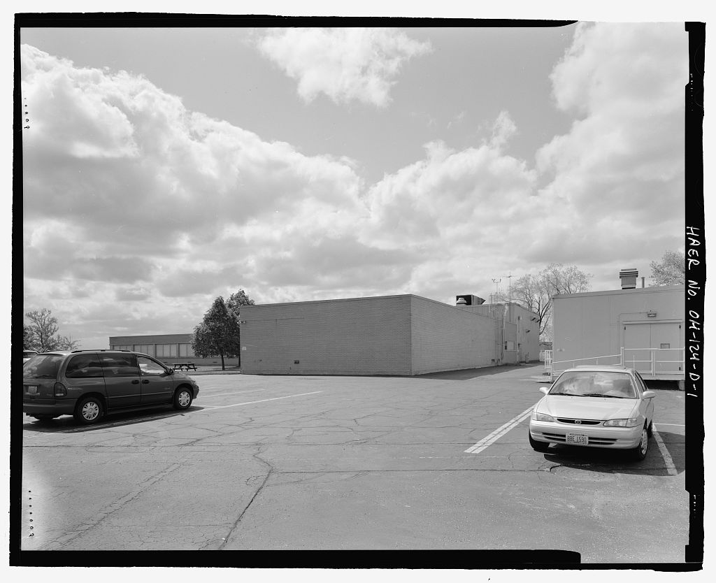
Nearly all the buildings are of similar design and contribute to a harmonious setting that reflects their common function. Description of Building The building has a T-shaped plan, in which the longer leg of the building houses offices while the shorter perpendicular section contains laboratories and the Rocket Engine Test Facility Control Room. Most of the building exterior is clad in buff-colored brick and is largely unornamented. The brick is laid in running or stretcher bond, 3 except in one area over the entrance canopy and over the granite planters at the main entrance. In these two areas, a soldier course of vertically laid brick accentuates the building features.
The use of limestone trim, granite planters at the main entrance, and insulated metal wall panels with vertical corrugations on the high bay created a visually interesting building in harmony with its surroundings. Most of the building is one story in height, but the southern part of the facility is a two-story, high-bay zone originally designed as a shop area. This part of the facility currently houses offices. The northern portion of the building contains the control room for the Rocket Engine Test Facility. A basement under the control room contains utilities, electrical switchgear, and an entry tunnel for steam pipes. The basement also provides access from below to the wiring chases, control console, and model board.
The roof consists of a four-ply built-up membrane laid over l" of insulation that rests on a steel deck. 4 Illustrations in the graphics section show the elevations and plan of the building. Office Wing: Except for the excavated basement beneath the control room, the building rises from a concrete foundation slab that measures l' in thickness. The office section of the building consists of eight bays. The lower portion of the exterior wall is buff-colored brick that terminates in a sill course 2 National Aeronautics and Space Administration. Lands of the Lewis Research Center (Cleveland: National Aeronautics and Space Administration, 3In a running bond all bricks are laid lengthwise with the vertical joints of one course centered between those of adjacent courses.
4 Drawing CE-101440- ROCKET ENGINE TEST FACILITY, GRC Building No. 100 (Ro9]<:et~M:gtn:e Test Facility- Rocket Operations Building Fr~pii-}::,,. HAER No. OH-124-D Page 5 just below a cut limestone belt. This belt forms the sills and a visual anchor for the windows. Each bay has a fresh air intake in its center, just above the concrete slab. Cut limestone mullions visually separate the bays. Lintels of cut limestone delineate the tops of windows. This continuous belt visually resembles a jack arch. Several courses of buff-colored brick extend between the top of the windows and a cut limestone coping that delineates the edge of the roof. Aluminum-frame windows are set on the limestone sill, and each window is divided into three sections in each bay.
Each section in the longest facade of the wing has two lights. Three bays form the short or end facade of this wing. The two outer bays have the same aluminum-frame windows of similar overall dimensions, however, these windows are divided into four sections, while the center bay has a three-section window. The upper light, comprising approximately two-thirds of the area of all windows, is fixed. Lower lights are hinged at the top to open outward. All exterior glazing is of heat- absorbing glass. Fourteen offices, each with a surface area of square feet, are arranged along the long sides of this wing. The short or end section contains three offices, two of which have a surface area of 195 square feet, and one of which covers 144 square feet.
Lobby: Entrances open into the north and south sides of the central portion of the building, where the two sections of the plan intersect. A small terrace on the north side of the building precedes the main entrance. Metal canopies protect both entryways. Originally there were exterior and interior sets of three single glass doors. These doors were replaced by single sets of double doors to create a wider opening and to comply with the requirements of the Americans with Disabilities Act. When the form of the door changed, the two steps leading to the small terrace were replaced with a ramp. Fixed granite planters flank the exterior doors and delineate the terrace. The doors open into a central lobby that measures 488 square feet and leads to the building wings and control room.
A three-dimensional scale model of the Rocket Engine Test Facility is on display on one wall of the lobby. As originally designed, the central portion of the building housed men's and women's restrooms, janitor's closets, a stairway to the basement, and a locker room with shower that was accessible only from the high bay. 5 High Bay: The high bay is sheathed in corrugated metal panels with a rigid insulating material on the inside face. The vertical corrugations provide a pleasing contrast to the otherwise horizontal lines of the building. These panels originally formed a workspace measuring approximately 60' x for a total surface area of square feet. The high bay measures 21 in height. Windows in the 5 Drawing CE-10144 l ~ ROCKET ENGINE TEST FACILITY, GRC Building No.
100 (Rocket'"Ei,~e-Test Facility- Rocket Operations Building 1'rop>J5i0fl HAER No. OH-124-D Page 6 high bay area consist of two sections. The upper section is a fixed aluminum-frame sash that measures about four feet square and contains six lights arranged in two columns of three lights. The lower section of one of these windows contains fourteen lights in an aluminum frame. The lowest, central, and uppermost lights are fixed and contain two lights, side by side. The two opening sashes between the fixed lights contain six lights arranged in two groups of three, side by side. These are contained in a frame that has a center horizontal pivot. Crank and lever systems within the high bay control the opening of these windows.
The east side of the high bay has thirteen of these window arrangements centered on the facade of the building. The south facade of the building is marked by four of the same window arrangements, two on either side of a centrally located rolling service door that retracts upward to form an opening that measures 14 square feet. 6 A pit measuring 12 square feet was centered along the north wall of the high bay area. Through this pit, equipment could be lowered into the basement area under the control room. 7 The original bridge crane, which travels along a north-south trajectory, moved heavy equipment around the mezzanine. 8 Around offices and laboratories were built in the high-bay area.
Mezzanines, accessed by ladders, accommodate heating, ventilating, air conditioning, and electrical equipment over these offices. Primary Building Function -The Rocket Engine Test Facility Control Room: 9 The northernmost wing of Building 100 houses the control room. A plan of the control room is included in the graphics section of this report. The windowless north and west facades of this facility are faced with brick. The east facade has four aluminum-frame windows that measure 4' x high. Three limestone panels, which measure wide, separate these windows. The upper half of each window features a single fixed light. The lower half is an opening light that pivots at the top of the sash. The control room is 60' long and 39' wide, and covers a total surface area of square feet.
A wall separates the office/work area from the main control room. This office/work area is 39' long and 12' wide. A stairwell in this room leads to the basement beneath the control room. The control room was a central location from which personnel managed the engine tests at Building Fuels and oxidizers for the engine being tested were also partly monitored from the control room. This room also provided a facility for sensing, monitoring, and recording engine 6 Ibid. 7 Drawing - 8 Drawing 9The descriptive material on the control room and its operation was obtained during a videotaped tour of the facility conducted by George Repas, who was employed as a hardware design engineer at the Rocket Engine Test Facility during most of the years that it operated.
ROCKET ENGINE TEST FACILITY, GRC Building No. 100 (Rocket E.ugias Test Facility- Rocket Operations Building 1?o~sA16iQ1V'\ HAER No. OH-124-D Page 7 performance during tests. Testing new and unproven rocket engine designs using hazardous fuels could be dangerous. A remote control facility enhanced safety and allowed the collection and storage of data in an area that was unlikely to sustain damage in the event of catastrophic engine failure. The protection of research data was essential in engineering development programs, since collected data enabled engineers to detect design inadequacies and use the results of experiments to develop advanced engines. The design of the control room followed standard practice.
The main control and instrument consoles were centrally located and were surrounded by model or control boards that showed the operating status of all major valves, pumps, motors, and actuators in the system. The control console and the model boards were schematic representations of the system, with colored lines representing pipes that carried the flow of reactants to the engine being evaluated. Removable panels in the floor allowed access to wiring chases. This design concealed the wiring between the control console, model boards, and data-recording units. 10 Electrical and electronic signals that conveyed control commands among the system components were carried over copper wire consisting of insulated single, multi-conductor, and coaxial cables.
Data acquired by sensors was similarly transmitted over copper cables. The only program that used fiber-optic cable was a recent hydrogen densification program that operated in the upper area of the Rocket Engine Test Facility. The model board on the southwest side of the room consisted of vertical aluminum panels measuring thick. These panels faced the test engineer and were painted with a schematic representation of the Rocket Engine Test Facility's piping system. This graphic representation corresponded to the physical layout of the facility. The back of each panel formed a base for the pilot lights and cabling. A steel angle iron framework supported the panels.
Indicator lights were positioned on the schematic diagram so that they corresponded to the locations of valves and actuators within the facility process piping. These pilot lights showed if the valve they depicted was open or closed. The main control console was a similarly designed tilted panel with a schematic diagram of the system rendered in colored lines representing the reactant and fluid delivery systems. The main console was constructed at a working height convenient for the test engineer. The panel contained switches that remotely controlled valves, actuators, motors, and fans at the test stand. The operation of the engine being tested was complex since the testing period was relatively short, and rarely lasted more than a few minutes.
During this brief duration transient events could occur that had implications for longer-term performance. The limitations of human reaction time precluded manual operation of an engine test. Real-time human operation and observation of a test did not yield much useful data, and close observation of rocket tests was dangerous. Consequently, the operation, sensing, and recording of engine tests were, for the most part, completed under the control of electro-mechanical devices or computers. The records of an 10 Drawing No. - ROCKET ENGINE TEST FACILITY, GRC Building No. 100 (Rocketi3ftgtM Test Facility - Rocket Operations Building HAER No. OH-124-D Page 8 experiment, including input factors such as timing and fluid flows, were stored.
Experimental results were later analyzed and plotted against outputs such as thrust generated by the engine, engine temperatures and pressures, and other performance criteria. In the pre-computer period of the late and early runs were controlled using electro- mechanical devices such as Eagle Signal timers. These timers were clocks run by synchronous motors programmed to close or open switches on a preset schedule. During this period, run data were analyzed and reduced by employees who were referred to as "computers" using slide rules and manual computation. Later, in the NASA designed and built solid-state logic circuits programmed using thumb wheel switches, which were made in many versions, to control engine test runs.
11 Programmable controllers were developed during the late These devices were originally known as With the development of the personal computer they were renamed programmable logic controllers, or The Rocket Engine Test Facility control system used programmable logic controllers made by the Modicon Corporation to replace the earlier electro- mechanical devices. A programmer would configure the PLC to tum the valves and actuators controlling fuel, oxidant, and ignition sequence according to a predetermined time schedule. The engine test runs were nominally controlled by the but test engineers could use a manual override when necessary. The engineers could press a "panic button" located on the main control panel to initiate an automatic shutdown, under PLC control, in case of an emergency.
12 Originally, the performance data of a run were recorded on magnetic tape, thermal paper linear recorders, multicolor pen recorders, or "Visicorders." Visicorders were made by Honeywell and could simultaneously record several events such as valve opening times, ignition, temperature, or pressure transients. In subsequent methodology developed during the raw data were reduced using one of two programs: TRADAR or CADDE. Lewis Research Center personnel wrote these programs specifically for rocket engine testing. These data were fed by direct digital data link to the Research Analysis Center (RAC) in NASA-Glenn Building In Building the data were further processed by IBM TSS and Cray 1-S computers, and then transmitted to the control room for analysis.
13 This system provided on-line data processing facilities to the control room, hard copy terminals, and monitors located in the rocket operations building control room. The system gave engineers and technicians what was, in essence, real-time analysis. 11 Thumb wheel switches are available in many configurations: Decimal, single pole 10 position-Binary Coded Digital, Binary Coded Hexadecimal, or resistor decade. They were a technological step in the transition from electro- mechanical to computer control. 12 George Repas, whose career as a hardware designer at the Rocket Engine Test Facility closely paralleled its years of operation, called this switch the "quiver point," because the engineer's hand would hover above this switch and "quiver" in readiness for an emergency shutdown.
13 Email letter from Kevin P. Coleman, Records and Electronic Forms Manager, History Office Liaison, NASA, John H. Glenn Research Center at Lewis Field, Cleveland, Ohio. ROCKET ENGINE TEST FACILITY, GRC Building No. 100 (Rocket ~i.M Test Facility - Rocket Operations Building tfop&-JS:1.~ HAER No. OH-124-D Page 9 The control room has undergone several re-configurations since Changing technology and the addition of a high-altitude rocket test stand and a turbo pump test stand required the addition of new controls and recording equipment. In the Rocket Engine Test Facility was modified to include a high-altitude rocket engine test facility, called Test Stand B. This was a chamber in which a rocket engine could be horizontally mounted.
The chamber was then closed and evacuated to simulate the vacuum of space. Ejectors maintained the vacuum during the test period. 14 The ejector control panel was on the northeastern side of the control room, next to the high-altitude test stand controls. Some controls for the high-altitude test stand, primarily fuel and oxidant valving, were the same as the controls for Test Stand A and were also activated from the main control console. A valve control rack was installed in the northwestern side of the control room. From this location, engineers could precisely manipulate valves under PLC control. Besides on, off, or partial settings, valves would be ramped up or down at controlled rates as required for any particular experiment.
In Test Stand C was added to Building This new stand was used to test seal materials and designs for liquid oxygen pumps or other components. The initial test program tested seals on a turbo pump rig. The controls for Test Stand C were located in a rack on the southeastern side of the control room. Conclusion: The Rocket Engine Test Facility control room was an essential element in NASA's Apollo Program to land men on the moon. The work accomplished here was critical to the development of liquid hydrogen as a reliable and safe rocket fuel. The control and recording systems illustrate a successful approach, in large measure developed by the facility's staff, to problem solving and creating an efficient and cost-effective methodology for rocket engine testing.
14 The ejectors at the Rocket Engine Test Facility are devices for removing air and rocket exhaust from the high- altitude test chamber. These ejectors are simplified vacuum pumps with no moving parts, and they consist of nozzles that discharge a high-velocity jet of nitrogen across a suction chamber connected to the test chamber. Air and rocket exhaust is entrained in the nitrogen and carried into a venturi-shaped diffuser that converts the velocity energy of the nitrogen into pressure energy. The Rocket Engine Test Facility ejectors are unusual in that they operate on nitrogen rather than steam. ROCKET ENGINE TEST FACILITY, GRC Building No. 100 (Rocket 'Engine Test Facility- Rocket Operations Building 'ftop~ ltim"' HAER No. OH-124-D Page 10 \ Sources of Information/Bibliography A.
Engineering Drawings: National Advisory Committee for Aeronautics - Lewis Flight Propulsion Laboratory - Cleveland, Ohio Building No. Rocket Engine Research Facility Architectural - Operations Building First Floor Plan- Drawing No. CE-101441 - National Advisory Committee for Aeronautics - Lewis Flight Propulsion Laboratory - Cleveland, Ohio Building No. Rocket Engine Research Facility Architectural - Operations Building North and East Elevations - Drawing No. CE-101442 - National Advisory Committee for Aeronautics - Lewis Flight Propulsion Laboratory - Cleveland, Ohio Building No. Rocket Engine Research Facility Architectural - Operations Building South and West Elevations - Drawing No.
CE-101443 - National Advisory Committee for Aeronautics - Lewis Flight Propulsion Laboratory - Cleveland, Ohio Building No. 100 - Rocket Engine Research Facility Architectural - Operations Building Control Room- Drawing No. -- National Advisory Committee for Aeronautics - Lewis Flight Propulsion Laboratory - Cleveland, Ohio Building No. 100 - Rocket Engine Research Facility Architectural - Operations Building Basement and Roof Plans - Drawing No. National Advisory Committee for Aeronautics - Lewis Flight Propulsion Laboratory - Cleveland, Ohio Building No. 100 -Rocket Engine Research Facility Instrument and Control Panels Room Plan and Suggested Framing Plan Control Room- Drawing No. ROCKET ENGINE TEST FACILITY, GRC Building No.
100 (Rock~ i,ft~itt@ Test Facility- Rocket Operations Building HAER No. OH-124-D Page 11 National Advisory Committee for Aeronautics - Lewis Flight Propulsion Laboratory - Cleveland, Ohio Building No. Rocket Engine Research Facility Television System Plan - Location of TV Equipment - Control Room Control Room-Drawing No. - NASA Lewis Research Center - Cleveland, Ohio Research Projects - Building No. 100 First Floor Plan -Architectural- Drawing No. - NASA Lewis Research Center - Cleveland, Ohio Research Projects - Building No. 100 Basement Floor Plan --Architectural - Drawing No. - NASA Lewis Research Center- Cleveland, Ohio Building No. 100 Proprietary Protective Signaling System- Drawing No. - B.
Interviews: Repas, George, Hardware Design Engineer Interview by the author, 28 May Cleveland, Video recording. Hardlines Design Company, Columbus, Ohio C. Secondary
 Block
Block