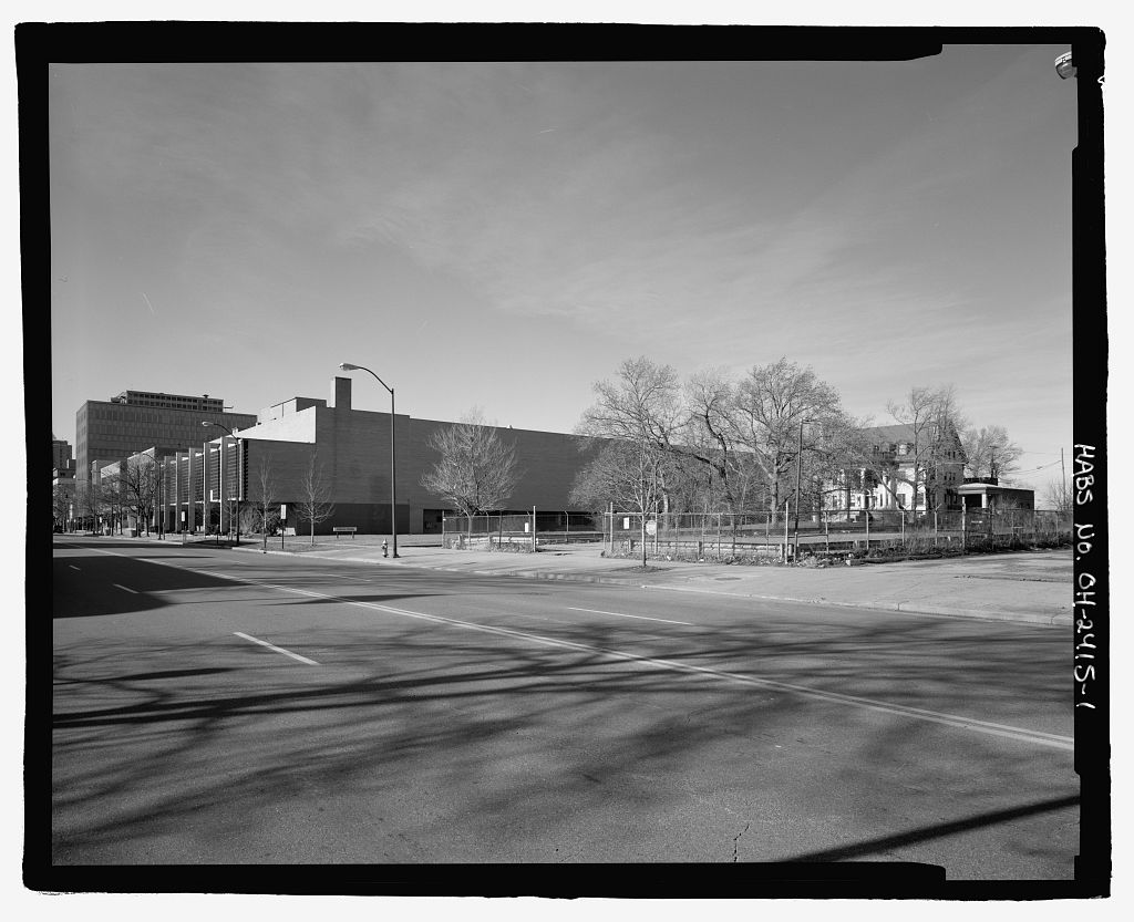
The AWT was the first wind tunnel in the United States, and possibly the world, capable of operating full-scale aircraft engines in conditions that replicated those actually encountered by aircraft during flight. In the NACA lacked a facility capable of testing modern full-scale engines. At the time that the AWT was constructed, it was claimed that the tunnel and its support buildings were the most costly grouping of equipment assembled to test a single engine. 12 The AWT required more electricity to operate than the entire city of Columbus, Ohio, 13 and the design required more engineering man-hours than that for the Boulder Dam.
14 Although the AWT was initially constructed to study reciprocating engines during World War II, the AWT s first 10 years were spent almost exclusively on improving the new technologies associated with turbojet, ramjet, and turboprop engines. Every early turbojet design and many of the second- and third-generation models were studied in the AWT. These tests included the nation s first jet aircraft (the Airacomet), the Bell YP 59A, the Westinghouse jet engine, and the Pratt & Whitney J57 engine. During this period, the tunnel contributed significantly to the improved capabilities of the turbojet through a steady stream of investigations on a number of engines. The AWT also played a primary role in resolving cooling problems for the B 29 bomber s Wright R engines during World War II.
In the late-1950s, the facility shifted its focus to space, and the AWT s large interior was used for Project Mercury qualification testing. In sections of the tunnel were sealed off to create two large test chambers, and the facility was renamed the Even though the facility had been mostly dormant since the mid-1970s, it had played a significant role in the progression of the nation s aerospace programs from the World War II reciprocating engine to the first turbojet models (see Fig. 9) to the more advanced jets of the through Project Mercury, the Apollo Program, and the Centaur missions.
Topography The AWT was located on a portion of the original 200 acres acquired by the NACA from the Cleveland Municipal Airport in late for an engine research laboratory (the current location ALTITUDE WIND TUNNEL HAER No. OH-132 Page 5 of NASA Glenn). The site had previously been used by the airport for parking and grandstands for the annual National Air Races (see Fig. 15 The airport borders the laboratory on the east, and the rest of the border loosely follows the Rocky River, which bows to the northwest around the main campus. The river valley is densely forested, but the main portion of the property is flat and featureless. The elevation of the AWT ranged from to above sea level.
The tunnel complex faced north in the wedge-shaped block of Ames, Moffett, Durand, and Taylor roads near the center of what is now NASA Glenn (see Fig. Other buildings directly related to the AWT were in the immediate vicinity. The nearby area contained several other laboratory buildings, including the Engine Research Building 5, ERB), the Icing Research Tunnel 11, IRT), and several small support buildings for the IRT. The IRT and AWT were constructed simultaneously and shared much of their support infrastructure. Nearly all of these original buildings had similar designs and finishes, which gave the area a unified appearance. Original Construction The ground was broken for the AERL on January 23, (See construction in progress in Fig.
The AWT was a crucial component in the overall design of the new laboratory and would be one of the most daunting challenges facing the NACA engineers. Although the Agency had experience with aerodynamic wind tunnels, this would be its first attempt at a controlled- atmosphere propulsion wind tunnel. Design work for the new engine laboratory was well underway at the NACA Langley Memorial Aeronautical Laboratory by the time of the groundbreaking. Edward Raymond Sharp had spent the previous six months working with Smith deFrance on the rapid construction of the NACA Ames Aeronautical Laboratory in Sunnyvale, California.
When the appropriation for the new engine research laboratory in Cleveland, Ohio, was approved, Sharp was recalled to NACA Langley to oversee the design and construction planning. After Sharp gathered a group from the NACA Langley administrative section, the plans for the AERL were drawn up in the offices of NACA Langley s Structural Resources Laboratory. The main design group for the AERL consisted of approximately thirty engineers and draftsmen, but smaller groups worked separately on specific facilities. Among these was a group led by Carl Bioletti at NACA Ames that worked on the tunnel s distinctive shell and drive system. This smaller group included Walter Vincenti, John Macomber, and Manfred Massa.
16 The AWT s ability to simulate both the pressures and temperatures of aircraft altitudes made its design more difficult than the pressure tunnels at NACA Langley and Ames. The simultaneous changes in pressure and temperature resulted in uneven stress loads. Pressure and temperature would decrease within the tunnel more rapidly than on the support rings, resulting in a great deal of stress on the rings. 17 Unable to find a method to calculate that type of thermal stress, Walter Vincenti at NACA Ames consulted with Stanford professor, Stephen Timoshenko, a leading expert on structural dynamics. ALTITUDE WIND TUNNEL HAER No. OH-132 Page 6 Timoshenko provided his former student with some calculations that resolved the issue, and Vincenti sent the calculations and notes to the Cleveland team.
18 Engineers at NACA Langley, including Al Young and Larry Marcus, designed the Shop and Office Building and other AWT support buildings. The team also planned the tunnel s fan, exhaust and makeup air systems, and air scoop. Young oversaw much of the design and co-wrote the design and performance specifications. 19 One of the most difficult tasks was designing a system for cooling the massive airflow. After viewing the struggles of the NACA Langley team, Willis Carrier convinced the NACA to forsake their new cooling coil design with its streamlined tubes. Simultaneous testing of the two systems proved the Carrier arrangement to be superior. Figure 13 shows the Carrier centrifugal compressors.
Since the refrigeration system was unique and had many previously untried features, Carrier built a scale model of the tunnel at its plant to facilitate the design. It was determined that the distribution of the coolant in large amounts and at specific pressures would vaporize the coolant throughout the entire tube in the cooling coils. The Carrier system required an enormous surface area for its cooling coils, so a zigzag design was developed that increased the coils surface area by four times. 20 The standard Carrier compressors were modified to use Freon-12. 21 There were still no buildings completed in August when Ray Sharp arrived from NACA Langley to oversee the construction.
He was followed in December by a large contingent of NACA Langley personnel as the United States entered World War II. This new group was managed by Ernest Whitney and Beverly Gulick. The AWT project engineers used Gulick s draftsmen and designers to help design certain aspects of the tunnel. 22 In a purely ceremonial event, AERL research was formally initiated on May 8, as an engine was run in the Propeller Research Building for NACA management, local dignitaries, and the media. 23 Just three days later, however, Commanding General of the U.S. Armies, Henry Hap Arnold, requested that the NACA s priority rating be elevated to Class D 1 to expedite the construction of the AERL. This request was approved by the Bureau of the Budget several days later.
24, 25 Unfortunately, the construction suffered delays and setbacks caused in part by competition with other agencies for wartime congressional funding. George Lewis traveled from Washington to Cleveland every Monday to visit the AERL and oversee its progress. 26 (See construction in progress in Fig. The design team moved from NACA Langley to Cleveland, the military provided special supplies, contractors were given new contracts and pressured to meet deadlines, and Congress approved additional funds. 27 In the end, the AERL was completed ahead of schedule but at nearly twice the original estimated cost. 28 Construction of the AWT, however, continued to stall and would not be complete for another year.
Design of the tunnel s electrical drive and steel structure was scheduled to be completed in February GE oversaw the creation of the tunnel s 18,000-horsepower drive motor. This powered a 32'-0"-diameter propeller that was designed and fabricated at NACA Langley. It ALTITUDE WIND TUNNEL HAER No. OH-132 Page 7 was shipped to Cleveland on May 28, and the pieces were assembled in the AERL s hangar. 29 After winning the contract for the AWT s refrigeration system and coils on March 16, the Carrier Corporation began an extensive test program. To ensure the performance of the system, Carrier designed many of the valves and pumps specifically for the AWT compressors.
30 Louis Monroe, a former employee of the Carrier Corporation, was responsible for bringing the complex refrigeration system online. 31 The Arthur E. Magher Company built the ammonia compressors, the Armstrong Cork Company installed the insulating pipe, the Collier Construction Company wired the Carrier equipment, and the York Corporation supplied the exhaust gas coolers, which Norris Brothers installed. The Pittsburgh-Des Moines Steel Company, which constructed much of the tunnel, also installed the cooling coils and headers, liquid and vapor lines, expansion joints, an exhauster trench, 32 the distribution header, the flash cooler pipe, coils, headers, manhole, and electrical ducts.
Installation of the flash cooler began in mid-June 33 The Refrigeration Building was percent complete by the end of August 34 The Sam W. Emerson Company commenced the excavations for the AWT in the spring of and completed the task by late December. Ray Sharp had negotiated a contract with Emerson to build the AWT Shop and Office Building for and to install the tunnel s foundation for an additional 35 Pittsburgh-Des Moines constructed most of the actual tunnel, test chamber, and control room. 36 This steel company, which had won many wartime government contracts, also constructed facilities at Los Alamos, battleships, Arnold Engineering Development Center s (AEDC s) Propulsion Wind Tunnel (at the Arnold Air Force Base), and landmarks such as the Gateway Arch in St. Louis, Missouri.
Beginning in mid-June with corner A, the turning vanes were installed over the summer of Each section of vanes took several weeks to erect. 37 The construction of the Shop and Office Building and the Exhauster Building was completed in September This was followed closely by the completion of the Refrigeration Building. 38 43 Figures 15 to 20 show the construction in progress. In the final months of construction, Harold Friedman was asked to design a system to subject the propellant for the test articles to simulated altitude conditions prior to the propellant s introduction into the engines. Friedman, just a couple years out of university, was given no real guidance on fuel behavior or on how to design the system.
The system he created used a vacuum tank to condition the fuel to the proper altitude. The facility began operations before the fuel system was finished, and it was not implemented. 44 Robert M. Pelkey, Inc., was hired on July 20, to complete the painting of the AWT, IRT, and test chamber. The control room, test section, and tunnel were completed in January 45 50 For the first test run at the tunnel, on February 4, Willis Carrier and a team of engineers were on hand to ensure that there were no malfunctions. ALTITUDE WIND TUNNEL HAER No. OH-132 Page 8 Alterations The AWT underwent a series of alterations throughout its thirty-year operating period.
These included exhaust system improvements, the addition of small subsidiary tunnels, the removal of internal components, and conversion into a vacuum tank facility. Because of the arrangement made with the Cleveland Electric Illuminating Company, the AWT initially ran only during the night. Chief of the Engine Installation Division, Abe Silverstein, configured the exhausters and air dryer to run a new small supersonic tunnel during the day, without the huge power loads of the refrigeration and drive systems. It was the first of three small tunnels built vertically atop one another and housed in the three-story Small Supersonic Tunnel Building (Fig. 21) between the AWT and the IRT. These three small open-circuit tunnels were known as the Stack Tunnels.
The first, capable of Mach was built in just ninety days and was operating by August 51 Mach and tunnels were added in and respectively. The tunnels were used to study the effects of boundary layers and inlets for jet engines. 52 In the basement of the AWT s Shop and Office Building was a small 4' x 10" Supersonic Wind Tunnel referred to as the Duct Lab. Like the Stack Tunnels, it utilized the AWT s exhausters for small-scale flow-physics studies. The Duct Lab was operating by November Even though the AWT had not operated in decades, the Duct Lab continued to be used through In response to complaints received immediately after the cessation of World War II, baffles were added to the Exhauster Building vent pipes to minimize low-frequency vibrations and noise.
The tunnel s reciprocating exhausters regularly rattled windows and doors over seven miles away. The near daily noise was considered to be almost unbearable by some residents. 53 Over a period of several weeks in October at a cost of the lab installed eight mufflers manufactured by Maxim Silencer. Aircraft speeds increased rapidly in the with the advent of the jet engine. The AWT s 500 miles-per-hour air-speed capacity was no longer sufficient to study modern engines. Engineers were able to use ambient pressure outside the AWT s test section in addition to the simulated pressure directly connected to the engine s inlet to increase airflow to over Mach 1 (Fig.
The tradeoff was that the effective size of the test section had to be reduced and could no longer accommodate a full aircraft, only an engine. 56 From May through December a number of modifications were made to modernize the AWT for the newer, more powerful jet engines. A permanent metal deck was installed across the test section to provide technicians with a steady platform on which to work on the engines. The largest upgrade was the addition of a smaller rectangular annex with new compressors to the northeast corner of the Exhauster Building. An exhaust gas cooler (Fig. pump house, and cooler pit were installed underneath the northeast segment of the tunnel. Additional cells were added to the western end of the cooling tower at this time, as well.
57 67 A air-expansion refrigeration turbine that was added to the makeup air system in increased the tunnel s cooling capabilities to 100 degrees Fahrenheit ( F). The engine ALTITUDE WIND TUNNEL HAER No. OH-132 Page 9 compressor could then be studied at high corrected speeds and with high-altitude turbojet starting. 68 A new fuel supply system was installed for the J 40 10 afterburner tests in This system included a new 4"-diameter fuel line that ran from the Exhauster Building to the fuel- conditioning room to the east of the Shop and Office Building s test chamber. 69 In the Central Air and Exhauster Building, which began operating in with the new Propulsion Systems Laboratory was linked to the AWT s exhaust system. The AWT had already been connected to the ERB s exhausters (Fig.
so now there were three air-supply systems to complement each other. These three systems combined to close a longstanding gap between the laboratory s airflow capacity and the test facilities needs. 70 The 6"-diameter pipe entered the top of the tunnel s northeast corner. The Garlock Packing Company created and installed the elliptical-shaped rubber expansion joint. 71 79 As a result, the AWT saw an improvement from seven to twelve pounds of air per second at and from fifty-one to sixty-six pounds of air per second at 80 In the AWT ceased to be utilized as a wind tunnel and was instead used for its altitude simulation capabilities and large interior space. The tunnel shut down from January to May for a leak test.
By early the turning vanes, coiling coils, and makeup air lines had been removed from the western end of the tunnel. This area was used for a series of Project Mercury tests (Fig. 25) that did not require an airstream. In bulkheads were inserted in the tunnel (Fig. 26) to create two large test chambers and the drive fan, exhaust scoop, and remaining turning vanes were removed. On September 12, the tunnel was named the In the Sverdrup Corporation was contracted to conduct an extensive preliminary engineering report to explore the costs and options for remodeling the SPC for use once again as a wind tunnel for icing and vertical or short takeoff and landing (V/STOL) testing. Sverdrup delivered cost estimates and a feasibility study for the future use of existing AWT structures. (Fig.
27 shows a model of the proposed rehabilitated AWT.) It was determined that the existing infrastructure was robust enough to be the basis for the new tunnel. 81 An AWT Project Office was established to oversee the proposed tunnel rehabilitation. Since the tunnel s internal elements had been removed during the creation of the a new test section, heat exchanger, two-stage fan system, exhaust scoop, and four turning vanes would have to be installed. 82 A Congressional Advisory Committee on Aeronautics Assessment cancelled the rehabilitation in March The AWT Project had consumed a substantial amount of personnel and financial resources, and it appeared that the actual rehabilitation of the tunnel would exceed the million already proposed.
The committee also questioned the AWT s predicted capabilities and suggested that the research needs could be met by existing wind tunnels. 83 ALTITUDE WIND TUNNEL HAER No. OH-132 Page 10 2.2 Events History World War II Less than twenty years after World War I, the United States was once again facing a European war and superior German aircraft. A report by George Lewis, NACA s Director of Aeronautics, describing his trip to Germany was the first intimation that NACA s Langley laboratory might be inadequate for the nation s future research needs. At the time, Langley, with its 400 employees, was the NACA s only research laboratory. In contrast, it is estimated that Germany had aeronautical researchers.
84 In addition, the NACA had concentrated its research almost exclusively on aerodynamics with only cursory propulsion work. Those at NACA Langley who were working on aircraft engines primarily studied single cylinders and extrapolated the test data for full-scale engines. This technique could produce misleading data. 85 As World War II approached, it was evident that aircraft would be as important as navies or ground troops. Although aircraft manufactured in the United States were numerous, they were slower and incapable of the altitudes that the German aircraft achieved. At the outset of World War II, U.S. aircraft engines were neither diesel nor liquid-cooled.
86 In response to George Lewis s report, the NACA set up a special committee under General Oscar Westover, then Chief of the Army Air Corps. It took three years for the committee to address the question of the relationship of the NACA to the defense of the United States in the event of war, but in Congress approved funding for the expansion of the NACA. 87 The NACA made the decision to create two new research labs Ames and the AERL. Ames, at Moffett Field, California, was designed to investigate high-speed flight. The AERL, in Cleveland, Ohio, was created to study aircraft propulsion systems, with the unique capability of testing full-scale engines in simulated altitude conditions.
George Lewis said, I feel confident today in saying that this new aircraft engine research laboratory will be the Mecca for all the world s aircraft engineers and research workers. 88 The centerpiece for the new engine laboratory would be the Engine Research Tunnel (Fig. which would be the nation s first wind tunnel capable of studying engine behavior in altitude conditions. Previously, there was no way of testing an engine under these conditions except with risky, time-consuming flight tests. The Engine Research Tunnel, which would soon be renamed the AWT, was designed to fill this void. Power, speed, drag, vibration, and cooling could all be analyzed in controlled conditions, making the AWT the most complete facility for testing full- scale engines prior to production.
This ability to test full-size engines instead of just a single cylinder resulted in a more rapid transition from design to flight testing. 89 Carlton Kemper predicted in March AERL is unique in having the only altitude wind tunnel in the world. We can expect that this one research tool will give answers to the military services that will more than offset the cost of the laboratory. 90 One of the most pressing military problems was the overheating of the Wright R engines that were used to power the new B 29 Superfortress. The B 29 was designed by Boeing as a ALTITUDE WIND TUNNEL HAER No.
OH-132 Page 11 long-range "Hemispheric Defense Weapon." 91 The bomber was the most sophisticated aircraft of its era, but the state-of-the-art R burned up regularly at the high altitudes at which the bomber was designed to 92 Even though there was tremendous pressure to complete construction of the AWT in order to analyze these R cooling issues, the first aircraft tested in the new tunnel was the new Bell XP 59A Airacomet jet (Fig. The Airacomet was the first U.S. aircraft to incorporate a turbojet engine. The AWT tests led to a 25 percent improvement in the aircraft s GE I 16 engine performance through a redesign of the inlets to allow better distribution of airflow.
93 Despite these enhancements, the XP 59A remained too problematic to be used for combat in World War II, and the design was eventually abandoned. 94 Because of the agreement with the Cleveland Electric Illuminating Company, the tunnel operated overnight (Fig. During the war, AWT employees were divided into four groups working two shifts: 3 to a.m., and 11 to 7 a.m. 95 Generally, the first shift broke down and set up the tests, and the second shift ran the tests. Engineers would often have to work all day, then operate the tunnel and test the engine overnight. The AWT and IRT at the AERL were used more frequently for military research during World War II than were the tunnels at NACA Langley or Ames.
A study of NACA wind tunnel testing from January to June showed that percent of the AWT and IRT s operating time was used for Army and Navy studies, in comparison to 57 and percent of the tunnel operating time at NACA Langley and Ames, respectively. 96 The AWT s most successful wartime study was the resolution of the B 29 cooling problems (Fig. which stemmed from poor cooling air circulation and irregular fuel mixtures. 97 The massive R were not allowing enough airflow to reduce the extreme exhaust heat. In addition, the fuel was injected before the supercharger, which resulted in the uneven distribution of fuel. AERL researchers developed a copper tube with nozzles that was placed around the engine.
They were able to measure the temperature of each cylinder and determine which ones were not receiving the proper amount of fuel. Small amounts of fuel were then sprayed into the cylinders of the nozzles that had not received enough fuel. 98 The AERL also studied the R s cowl inlets, particularly the flap design. A right inboard nacelle with its eighteen-cylinder engine and wing section was used to examine a wide range of cowl flap configurations in the AWT to study the cooling-air pressure drop and distribution, and drag. It was found that sliding flaps required sixty to eighty hp less than the original chord flaps did. 99 The AERL researchers also were able to broaden the B 29s flight range and increase its armament capabilities by increasing its fuel efficiency by eighteen percent.
100 Flight testing afterwards revealed that the modifications resulted in specific range improvements of up to thirty-eight percent. This improvement translated into an altitude increase of or a gross- weight increase of pounds at sea level or of pounds above 101 Despite the NACA s stated wartime mission to study only existing aircraft types, only one other of AWT s eight wartime tests was on a piston engine, the experimental 1 Skypirate ALTITUDE WIND TUNNEL HAER No. OH-132 Page 12 torpedo bomber (Fig. The Skypirate s R Wasp Major was the largest reciprocating engine to be mass produced in the United States at the time. The R radial engine used two contrarotating propellers to produce hp.
102 Early developmental problems included sticking of the piston ring and overcooling of the piston assemblies. 103 Beginning in mid-November the R engine was tested in the AWT for a little over a month. The Skypirate was too large to be used on pre-Midway carriers, and the concept of multiseat torpedo bombers was falling from the military s favor by the time that the Midway carriers were put into action in late It would have been the largest aircraft of its time used on an aircraft carrier had the program gone forward. 104 Development of the Turbojet Despite its promise, many in the United States and the NACA thought that the gas turbine engine was not a viable alternative to the well-developed reciprocating engine.
It was believed that the weight of the turbine s components would exceed the aircraft s capabilities and require too much fuel. 105 Although this was initially a realistic assessment, as the turbojet was perfected during the and these obstacles were overcome. The turbojet s speed, its ability to use a wide variety of fuels, and the eradication of the reciprocating engine s propeller made the turbojet even more appealing. 106 In Great Britain, Frank Whittle had patented his idea for a gas turbine engine in and by had run successful static tests. Unaware of Whittle s engine and working independently in Germany, Hans von Ohain patented his own turbojet design in Soon afterward, von Ohain began collaborating with Ernst Heinkel to integrate the new engine into a working aircraft.
On August 27, the Heinkel He178 became the first jet aircraft flown successfully. Upon assuming control of the U.S. Air Corps in General Henry Arnold called a meeting to identify vital research and development areas for the Air Corps. One of the items on the table was the jet-assisted takeoff. Both Jerome Hunsaker and Vannevar Bush revealed the NACA s closed-mindedness at the time by openly deriding the proposal. 107 Abe Silverstein later explained that the NACA was primarily an aerodynamics-based agency at the time and that nobody was really looking ahead. 108 In the meantime, the Europeans were beginning to fly turbojets successfully. By the Italians had developed their own variation of the jet engine.
In early the first rocket- propelled aircraft was flown in Germany; and on May 15, the British flew their first jet aircraft, the Gloster E.28/39. The first substantive development with the turbojet occurred on July 19, when the German Messerschmitt Me-262 Schwalbe became the world s first operational fighter jet. The Me-262, which incorporated two Junkers Juno 004 jet engines, could fly at 540 miles per hour. In addition, the concept of swept wings, below-the-wing nacelles, cannons in the nose, and wing slots were all initiated on the Me-262. 109 Although the Americans had decided to fight World War II with existing piston aircraft, it was obvious that jets were the future of aeronautics. In March, the NACA called Dr.
William Durand out of retirement to head a Special Committee on Jet Propulsion to study the Whittle engine design. 110 This would lead to the July successful ground testing of the NACA Jeep gas turbine engine at NACA Langley. The Jeep engine was developed independently of the Whittle ALTITUDE WIND TUNNEL HAER No. OH-132 Page 13 engine and was based on an axial-flow design that was limited. After a failed test for NACA committee members, the program was put on hold permanently in March 111 General Arnold had visited Britain in April to watch the first flight of the Gloster E.28/39. Through the Lend-Lease agreement, plans for the Whittle engine were secretly brought to the United States so that American engineers could duplicate the engine.
112 A GE group in West Massachusetts, was selected to replicate Whittle s W 1B engine. The result was the 1250-pound-thrust GE I A centrifugal flow engine. 113 On October 3, Bell Aircraft Corp. was given the task to construct an aircraft that would incorporate the I A engines. This aircraft, the XP 59A Airacomet, used two of the jet engines mounted under the wings and adjacent to the fuselage. 114 Although it flew, it did not perform well and provided little performance enhancement over the gas turbine version. 115 By July GE had created an updated version of the I A engine, which was called the I 16, or J 31. The 1650-pound I 16 was more powerful, but its additional weight prevented the XP 59A from performing any better than with the I A.
116 In the fall of the GE I 16 engine was secretly brought to the AERL for testing in the newly completed Jet Static Test Laboratory. The I 16 tests were under guard and disguised as a Supercharger Project. 117 NACA and GE researchers were able to improve upon the initial Whittle design. 118 Eight additional Airacomets were produced during and test flown at various locations, including the Muroc Army Air Field (now Edwards Air Force Base). Problems still remained, though, particularly in regards to uneven airflow through the intakes. Abe Silverstein (Fig. 33) flew to the GE plant to examine the engine and vowed to get it running.
119 A XP 59A Bell aircraft was brought to Cleveland, and the wing tips and tail were cut off so that the entire fuselage and engine would fit into the AWT s test section (Fig. It was tested daily by three shifts from February 4 to May 13, 120 AERL researchers were able to redesign the inlets allowing better distribution of airflow. This improved the aircraft s performance by 25 percent. 121 In addition, the I 16 engine was tested separately at the AERL without the aircraft. Despite the enhancements made in the AWT, the XP 59A remained too problematic to be used for combat in World War II, and the design was abandoned. 122 The AWT returned to turbojets after the mid-1944 B 29 studies.
The Westinghouse 19B and engines were tested in fall and the GE TG Lockheed YP 80A and and a 20"-diameter ramjet were studied in These early tests produced the first operational afterburners. On October 22, Westinghouse Electric became the first company to begin work on an American-designed turbojet engine. They were contracted to build two 19A axial-flow turbojet engines. By March Westinghouse had successfully built a 19A engine, and on July 5 they concluded a 100-hour endurance test. The 19A led directly to several other jet engines, including the 123 ALTITUDE WIND TUNNEL HAER No. OH-132 Page 14 Beginning in September the Westinghouse 19B was tested for two months in the AWT.
The tests focused on the operation of the 19B s new designs, the 19B 2 and 19B 8 prototypes, along with experimental prototypes, the 1 and 2B. General performance studies were conducted, the fuel nozzles were modified, and the combustion chamber setup was altered frequently. However, the combustion chamber alterations did not appear to increase the engine s performance. The 19B engines suffered combustion blowouts above and failed to restart on a consistent basis. The 1 performed well at altitudes of to and had satisfactory starting characteristics. In addition, the 19B had difficulty starting at any altitude, whereas the 1 started satisfactorily up to 124 Another important early turbojet test was the Lockheed YP 80 Shooting Star with its GE I 40 engine.
The Shooting Star was the first complete jet aircraft manufactured in the United States and was the first Air Force aircraft to fly faster than 500 miles per hour. 125 Flight testing of the two YP 80As commenced in August and in early September, the Air Force dispatched two to Britain and two to Italy to try to neutralize the Messerschmitt Me262 s successes. Despite being placed on the highest priority, the YP 80As could not be produced in large enough quantities to have much of an effect in the war. In addition, the aircraft continued to suffer operational problems, resulting in the deaths of several pilots. 126 Similar to the Bell XP 59 tests, the entire YP 80A fuselage was installed in the AWT test section (Fig.
One of the primary areas of research was the examination of the I 40 s thrust performance at high altitudes and the attempt to predict that thrust from sea-level measurements. AERL researchers successfully created a curve for the I 40 s thrust at all altitudes. 127 Follow-up studies with the a modified Shooting Star, found that turbine efficiency and compressor efficiency were not affected by altitude, but that combustion efficiency was reduced with increased altitude. Even though fuel consumption during normal engine speeds was unaffected, the engine s thrust was diminished with altitude. 128 After different tailpipes were analyzed, it was determined that a short-nozzle, uniform-diameter tailpipe outlet was the most efficient.
129 After the war, the majority of the AWT s research involved fundamental studies on the operational characteristics of aircraft engines and performance studies while the engine was firing. The researchers studied reciprocating, turbine-propeller, turbojet, ramjet, rocket, and compound engines most of which were tested under operating conditions across a full range of altitudes, velocities, and engine speeds. The GE TG 180 and TG 190 and the Westinghouse 24C were studied repeatedly in the tunnel. Tests of the GE TG 100A and the Armstrong-Syddeley Python (Fig.
36) turboprops were the basis for the successful Advanced Turboprop Program of the The NACA s Cleveland laboratory, including the AWT, spent a great deal of time studying the ramjet combustion process, but by the late the basic combustion process was still not understood very well. 130 The AWT was used to increase the turbojet altitude range from to by increasing the combustion chamber performance. Diffuser alterations increased compressor efficiency by fifteen percent. Studies of the pressure readings throughout the diffuser revealed the cause of the ALTITUDE WIND TUNNEL HAER No. OH-132 Page 15 problem, which was easily fixed. 131 The AWT was also instrumental in the redesign of the air inlets, which resulted in a fifteen percent improvement of turbojet ram pressure recovery.
132 Jet engines grew in size and capabilities in the late and early The second generation of turbojets was faster and more powerful. According to a NACA Lewis budget chart, turbojet thrust increased from to pounds between and 133 The Westinghouse J 40, Allison J 71 and T 38, Pratt & Whitney J57 (Fig. and Rolls-Royce Avon engines were studied in the AWT during the early The AWT was operating more in the early than at any other time. It also was in use more often than any other major facility at the laboratory during this period. The Pratt & Whitney J57 axial-flow dual-compressor engine was one of the most enduring of the second wave of turbojet engines. The J57 P 1 was a development model that employed two coaxial compressors, corresponding coaxial turbines, and a fixed-area nozzle.
134 This pound-thrust engine was used on the F 100 Super Sabre, B 52 Stratofortress, Lockheed U 2A, Boeing C the F and numerous other aircraft. It was studied several times in the AWT. At the request of the U.S. Navy s Bureau of Aeronautics, the engine s general performance characteristics were examined in the AWT from December until February This was followed by studies of fixed-area nozzles, inlet pressure, and fuel flow characteristics. From January to May a number of different exhaust nozzles were tested on the J57 in an effort to stem excessive engine noise. 135 The world was changing in the and soon the interest in aeronautics would be subjugated to space. NACA Lewis would play a prominent role in this new field.
A series of AWT tests in the spring of served as a portent for the new era. NACA Lewis researchers had been studying high-energy propellants for years. In the mid-1950s interest in liquid hydrogen as a propellant intensified. It was considered to be a dangerous material and it had to be stored cryogenically, but its low weight and high-energy yield were unrivaled. Although it would go on to be a principal component of the space program, Director of Research, Abe Silverstein, initially conceived of it as propellant for long-range aircraft. One of the early steps was determining if liquid hydrogen could be safely operated in an aircraft fuel system. In NACA Lewis researcher Harold Kaufman conducted full-system tests of a liquid-hydrogen fuel system with the J65 B 3 engine in the AWT (Fig.
The system, which was identical to the one intended for use on a B 57 aircraft, was checked using both the jet fuel and hydrogen modes. A couple of modifications allowed the engine to be tested at higher pressure levels and, thus, at altitudes to higher than during previous AWT tests. Unlike earlier turbojet studies in the AWT, which used external makeup air, this test used tunnel air. As a result, the exhauster only had to make up for tunnel leakage, rather than for leakage plus external airflow. 136 This test also utilized an exhaust diffuser rather than the usual nozzle. With nozzles regulating the exhaust airflow, the tunnel pressure was less than half of the turbine s total pressure. The diffuser permitted the tunnel pressure to be almost the same as the turbine pressure.
137 ALTITUDE WIND TUNNEL HAER No. OH-132 Page 16 Kaufman found that the performance of the engine with jet fuel decreased significantly over whereas the engine with hydrogen fuel operated smoothly to at least and its blowout altitude exceeded the tunnel s capabilities. Kaufman also found that the higher specific heat of hydrogen caused the turbine to produce a greater amount of thrust than obtained from jet fuel. 138 During this test period, Abe Silverstein and Eldon Hall wrote a report that foresaw liquid hydrogen performing missions that would surpass those of traditional hydrocarbon fuels.
139 Although switching between the jet fuel and hydrogen tanks was tested numerous times in the AWT with satisfactory results, and Walter Olsen, Head of the Fuels and Combustion Division, felt that these extensive ground tests had proven the system s ability, Silverstein insisted on a flight test. 140 Silverstein secured a contract to work with the Air Force to examine the practicality of a liquid-hydrogen aircraft. The endeavor was termed Project Bee. 141 A new B 57B aircraft was obtained by the Air Force especially for this project, and a liquid- hydrogen production plant was built in nearby Painesville, Ohio. The aircraft was equipped with 23'-0"-long wing tanks, one of which was modified so that it could be operated using traditional or liquid-hydrogen propellants.
The other tank would be used to store helium which would be used to pump the hydrogen. 142 Several dry runs were flown in the fall of with the first attempt at hydrogen-powered flight on December 23, The intention was to take off using jet fuel, switch to liquid hydrogen over Lake Erie, burn all its liquid hydrogen, then switch back to jet fuel for the landing. The first two flights failed to make the liquid hydrogen switch, but the third attempt in February was a success. 143 These flights would later be used to help convince NASA leadership that liquid hydrogen was safe to use for the Apollo Program.
NACA Lewis constructed new, more powerful facilities such as the 8- by 6-Foot Supersonic Wind Tunnel in and the Propulsions Systems Laboratory in The 10- by 10-Foot Supersonic Wind Tunnel in led to the decreased use of the AWT in and despite a major modernization project in 2.3 Contemporary Wind Tunnel Facilities Wind Tunnel Operation Wind tunnels were built in a variety of sizes and shapes with varying speeds, depending on the current technology and the areas of study that they were designed for. There are two basic wind tunnel configurations open loop and closed loop. The former are straight tubular designs in which air is either pushed or pulled through by a fan or compressor and blown out the other end.
The latter are square tunnels in which the airflow is cycled back through a fan or compressor and reused. For both configurations, the passage for the airflow is usually narrowed upstream from the test section to provide the maximum velocity for the test article. The experimental hardware is installed in a test section near the middle of the tunnel. These test sections can range from just inches in diameter to the larger-than-a-football-field 80- by 120-Foot Wind Tunnel at the NASA Ames Research Center. ALTITUDE WIND TUNNEL HAER No. OH-132 Page 17 Wind tunnels can be designed for specific uses. Some wind tunnels are pressurized to better control the airflow. Some facilities have moveable walls to provide the optimal flow for an individual test.
The AWT was the nation s first wind tunnel built to study engine performance in altitude conditions. Altitude is simulated by reducing the pressure and temperature of the air within the tunnel. Propulsion wind tunnels require the venting of engine exhaust so that it does not contaminate the airstream. Wind Tunnel Development Although various methods of studying the principles of flight had been attempted before, the first true wind tunnel was created in Great Britain by Frank Wenham in Wenham constructed a 12'-0"-long wooden tunnel in which models could be inserted. A steam engine created the airflow through the 18" x 18" horizontal passageway. 144 In after several failures at Kitty Hawk, North Carolina, the Wright Brothers built a tunnel in Dayton, Ohio, similar to Wenham s.
The 16" x 15'-0"-long, twenty-seven mile-per-hour tunnel produced important lift data for the Wrights. 145 Earlier that same year, Albert Zahm had built a x draw-through tunnel at Catholic University in Washington, DC, that dwarfed any of its contemporaries. Although Zahm s tunnel suffered problems because of uneven power levels and atmospheric instability, its method of airflow control and instrumentation would be used by others for years. 146 Zahm s tunnel and those following benefited from the replacement of steam engines with more efficient electric- powered engines, which allowed greater wind speeds at a lower cost. 147 Russia, France, and Great Britain all constructed substantial wind tunnels after the turn of the century.
148 The most influential, though, were Ludwig Prandtl s tunnels built at the University of Gottingen in Germany (Fig. Prandtl s first tunnel was a rectangular closed-loop that used turning vanes in the corners and a honeycomb screen across the width of the tunnel to straighten and guide the airflow around the corners without losing energy. Although this new closed-loop design was revolutionary, from its first runs in Prandtl s first tunnel was seen as a stepping stone to a larger more complex tunnel. 149 Delayed by the war, Prandtl s second closed-loop tunnel did not become operational until The rectangular design allowed pressurization and humidity control and required less energy to operate since the airflow was recovered.
The tunnel s throat was expanded upstream, narrowing sharply just before the test section to increase air speed to an unprecedented 120 miles per hour. 150 Prandtl s tunnels were innovative in many ways and influenced almost all subsequent wind tunnels. The aeronautical industry in the United States also was constructing wind tunnels. In with the foundation of his aircraft company, William Boeing built a x tunnel and donated it to the University of Washington in exchange for the foundation of an aeronautics program at the university. In the university began construction of the x 250 miles per hour Kirsten Wind Tunnel, which was used extensively on Boeing s B 29s during World War II. 151 ALTITUDE WIND TUNNEL HAER No.
OH-132 Page 18 NACA Wind Tunnels One of the primary motivations for the foundation of NACA Langley in was the construction of a wind tunnel. Its first tunnel, however, a low-speed, no-return facility built in was primarily a training tool whose data were not relevant to full-size aircraft. 152 NACA Langley s Variable Density Tunnel (Fig. proposed in by Dr. Max Munk, improved upon Prandtl s closed-loop tunnel and foreshadowed the sophisticated tunnels of the future like the AWT. Munk had been a student of Prandtl at Gottingen and had designed a massive, but unbuilt, pressurized tunnel for the Zeppelin company. 153 The VDT was the first U.S. tunnel to forgo normal airflow for highly pressurized air.
The tunnel used a large steel tank in which the atmosphere could be pressurized, but it maintained a wooden test section to negate Reynolds number concerns. 154 The VDT pressure tunnel, which became operational in could subject large-scale models to speeds up to 250 miles per hour and to pressures from subatmospheric up to several atmospheres. NACA Langley continued to put an entire collection of increasingly complex wind tunnels into operation.
The next was the Propeller Research Tunnel in followed by the Vertical Spin Tunnel and Atmospheric Wind Tunnel in the Full Scale Tunnel in the 8-Foot High Speed Tunnel in and the 19-Foot Pressure Tunnel of The which could simulate pressure altitudes of and speeds of 500 miles per hour, and the 19-Foot Pressure Tunnel, which combined a large test section with 250 miles-per-hour speeds, were significant steps forward in flight simulation. 155 The PRT was the nation s first tunnel built to study aircraft engines. Although it was an atmospheric tunnel and could only generate speeds to 100 miles per hour, it was significant because entire airplanes were tested with their engines running.
The AWT would take this concept to the next level, by testing full-scale engines in actual flight conditions and at higher speeds. The first supersonic tunnel in the United States was a 9" Mach 2.5 tunnel that was put into operation at NACA Langley in July Three years later, Langley began work on a x supersonic tunnel. 156 As World War II approached, the wind tunnels at Langley were being used more and more for the development of military aircraft. This testing grew to such a level that by the tunnels were operating twenty-four hours a day so that basic research could continue as well. 157 Two identical x tunnels and a 16'-0"-diameter tunnel were constructed at the NACA Ames Aeronautical Laboratory as planning for the NACA s Cleveland engine laboratory was beginning.
The massive x Full Scale Wind Tunnel at Ames was added in In the NACA was operating eleven wind tunnels at Ames and Langley. By the NACA had twenty-five tunnels, including five in Cleveland. Altitude Wind Tunnels New German wind tunnels in the early included three supersonic tunnels at Peenem nde, a 280 miles-per-hour tunnel with an almost x test section, a vertical spinning tunnel, a x tunnel, and others. As postwar Allied expeditions discovered, two hypersonic tunnels, a Mach 7 to 10 tunnel, a x supersonic tunnel, numerous small supersonic ALTITUDE WIND TUNNEL HAER No. OH-132 Page 19 tunnels, and an altitude wind tunnel were among the facilities being prepared for operation when the war ended.
158 The National Bureau of Standards, Naval Aircraft Factory, and the Army Air Corps Wright Field had successfully designed pressure tanks that could simulate the temperatures and pressures associated with altitude, but they could not incorporate the benefits of a wind tunnel. On the other hand, the Wright Brothers Wind Tunnel at the Massachusetts Institute of Technology (MIT), completed in could simulate altitudes of with speeds of 400 miles per hour in a wind tunnel setting but was not capable of running aircraft engines during the test. MIT began constructing wind tunnels in under the supervision of future NACA Director Jerome Hunsaker. The Wright Brothers Wind Tunnel was used extensively throughout World War II and remains active as a training tool for MIT students.
159 The wind tunnel complex at the Wright Patterson Air Force Base included the 10-Foot Wind Tunnel, which could simulate altitude conditions up to The tunnel became operational in January and was closed in 160 The S1 MA wind tunnel located in the French Alps can fire engines at altitudes up to The French Aerospace Lab (ONERA, Office National d Etudes et de Recherches A ronautiques), built the tunnel in at Modane-Avrieux. It is powered by water turbines and includes spray bars to conduct icing tests when the ambient air is cold enough. 161 The Propulsion Wind Tunnel at the AEDC can test jet and rocket engines at altitudes and at much higher speeds than the AWT could. The PWT only operates at speeds above Mach it is incapable of producing low-speed altitude conditions.
It began operation in and maintains an active test schedule today. 162 The AEDC facilities, in general, tended to be used more for the qualification and development of engines, whereas NASA Glenn s current facilities are geared more toward research and the study of engine dynamics. 163 3.0 Architectural Information Altitude Wind Tunnel The AWT has several primary systems: the wind tunnel, the airflow system, altitude simulation system, and the test chamber. Figure 41 is an aerial photograph of the AWT and surrounding buildings in 3.1 Wind Tunnel The AWT was AERL s first and largest wind tunnel until it was converted into the SPC (Fig.
Its central location at the AERL allowed it to interact with several other facilities and buildings, including the IRT, ERB, and The AWT itself required a large amount of infrastructure and several support buildings. These included the Shop and Office Building, the Exhauster and Refrigeration buildings, Cooling Tower No. 1, and the Air Dryer Building. The facility was powerful enough to support several small wind tunnels. The AWT could test full-scale aircraft engines under the airspeed, altitude, and air quality conditions found during flight. Airspeeds up to 500 miles per hour were created by a ALTITUDE WIND TUNNEL HAER No. OH-132 Page 20 diameter propeller that was spun by an engine in the Exhauster Building. The airflow was straightened by turning vanes located in the tunnel corners.
To simulate the cold temperatures found at high altitudes, a powerful cooling system in the Refrigeration Building could reduce the tunnel s temperature to 47 F as the air passed through accordion-like cooling coils in the wide end of the tunnel. The Exhauster Building contained large compressors that removed air from inside the tunnel to create the thin atmosphere found at high altitudes. The engine being tested was installed in the 20'-0"-diameter test section and operated remotely from the control room. A myriad of instruments recorded the tunnel conditions and engine performance during the tests.
The engines exhausted contaminants, which were removed from the tunnel through an airscoop located just beyond the test section; and fresh air was introduced into the windstream prior to the test section to make up for the exhausted air. The tunnel was long on the north and south legs, and long on the east and west legs. The larger west end of the tunnel was in diameter throughout (Fig. The east side of the tunnel was in diameter at the southeast corner and in diameter at the northeast. The throat section, which connected the northwest corner to the test section in the middle of the long northern leg, narrowed sharply from to in diameter. The test section was in diameter. The courtyard inside the tunnel loop was long and approximately 40' wide at the east end and 18' wide at the west end.
164 Figures 44 to 51 show several photographic views of the tunnel. Structure and Foundations The tunnel was supported by a large elliptical support ring in each corner, a ring in the Shop and Office Building s test chamber, and a series of 120 support rings, which lined the tunnel at intervals. Eight of the 120 support rings and the four larger corner rings were anchored to concrete piers that elevated the tunnel at varying heights (Fig. 165 These six primary support rings ranged from to wide at the base, to wide at the top, and to high. 166 The tunnel was elevated using unique concrete and steel piers. The midpoint of the twelve main rings connected to vertical steel supports. Steel rollers (Fig.
53) between the piers and the rings were used to bear the tunnel shell in a way that allowed the shell to contract and expand during the tunnel s dramatic temperature and pressure fluctuations. The 1'-10"-long, 4"-diameter rollers were connected at the tips to horizontal steel spacer bars. One row of five rollers was stacked perpendicularly on a second row of five rollers. These layers were attached to a beveled base on top of the pier. 167 Below the rollers the pier was encased in a concrete pylon (Fig. 54) that extended to into the ground. 168 The wide western end of the tunnel rested on the ground but had a large concrete support in the V-shaped area. Fourteen concrete pylons of varying sizes supported the other portions of the tunnel.
These were laid out in pairs with one on the exterior of the tunnel and another inside the loop. 169 ALTITUDE WIND TUNNEL HAER No. OH-132 Page 21 The throat section was supported by the balance chamber. The external portion of this support consisted of two vertical and two diagonal I beams on each side of the tunnel with a web of smaller horizontal and vertical steel beams. These beams were sunk into a single concrete base approximately 48" high and 22' wide. An H-shaped concrete support bore the weight of the tunnel on each end as it entered and exited the test chamber. By the concrete and steel pylons showed rust and some scaling. Figures 55 to 59 show the various support structures for the AWT.
Shell The AWT s shell consisted of two layers of steel with a layer of insulation between (Figs. 60 to The inner steel layer was the primary tunnel structure. Because of the AWT s altitude simulating capability, the steel used to construct the shell was both thicker and stronger than that used on other contemporary tunnels. The 1"-thick steel could withstand external pressure when the tunnel was evacuated to simulate high-altitude pressure levels. A steel alloy similar to the current ASTM International A710 Grade A3 steel plate was used to endure the low temperatures of the high altitudes without becoming brittle. The chromium provided extra hardness, and the copper was used to resist corrosion.
170 A 4" layer of glass wool was installed with steel mesh over the inner tunnel shell to retain the tunnel s low operating temperatures. The outer steel shell was then constructed over this layer to protect the insulation from the environment. 171 The outer shell of the tunnel was a weather shield and provided physical protection for the AWT s insulation. It was composed of x steel squares welded vertically in succession in between each of the 120 support rings and four corner rings. Two of these forms were welded together to form a single section of the tunnel. 172 The exterior of the tunnel was relatively smooth except for the four corner rings, which jutted out several feet.
The valve that connected to the Small Supersonic Tunnel Building jutted out on the southern leg near the west corner, but it was sealed off in the The east side of the tunnel included a portal for the drive shaft near the southeast corner and for the exhaust pipe near the northeast corner. The western side had a number of cooling system ports and two makeup air valves. A metal stairway provided access to the cooling line ports. Top of the Tunnel By the mid-1940s, a series of stairs, ladders, and platforms had been built on the top of the tunnel (Fig. Access was provided by doorways off the east and west sides of the test chamber. The walkway originally led from the west door over the throat section with stairs leading to the top of the west end of the tunnel.
The walkway, interrupted only by the four corner rings, followed the top of the tunnel until ending at the west side of the test section. Small permanent ladders and platforms were used to climb over the corner rings. The pathway had a steel handrail approximately 3' high with a second horizontal bar segmenting it. Steel-grated platforms replaced the original wooden platforms by mid-1945. 173 In the walkway and its components were rusted but in relatively good shape. ALTITUDE WIND TUNNEL HAER No. OH-132 Page 22 Coating of the tunnel with a protective gray paint appears to have ceased in the mid-1990s. Rust began to appear on the exterior of the tunnel by and was extensive by The outer shell of the top of the tunnel would bow under human weight.
Interior Walls The interior of the tunnel was smooth and tubular except for the corners (Figs. 65 to The approximately 3'-wide corner ring surfaces were squared but flush with the tunnel walls. The inner tunnel nexus at the western end had an approximately 3'-wide flat ramping piece that separated the north and south legs. The steel walls were composed of 52"-long, 60"-wide rectangular steel plates aligned vertically. When the tunnel was still operating, the long south leg housed the drive fan. The interior of the south leg had few obtrusions except several eyehooks that were welded to the lower walls for shroud separation tests in the In recent years, several rectangular holes were cut into the lower half of the tunnel walls; these revealed the insulation, mesh, and outer shell.
The wide 51'-0"-diameter western leg contained the makeup air nozzles, cooling coils, and turning vanes during the facility s years as a wind tunnel. Although these items were removed in the interior of the western wall still had a large number of obtrusions afterwards (Figs. 72 to The northern and southern sections of the wall each contained makeup air nozzles and three rows of four nozzles and one row of two smaller nozzles that fed the cooling coils. These were severed and capped in The throat section (Figs. 75 to 77) narrowed over a span of from a diameter of at the northwest corner to at the test section. This contraction accelerated the airflow to maximum speed through the test section.
The eastern leg was mostly obstruction free except for the drive shaft passing through the southeast corner and the exhaust pipe in the northeast corner. The shaft was removed and the portal was sealed in (Figs. 78 and In the overall condition of the interior of the tunnel was fairly good considering it had not been painted in over thirty years (Figs. 80 and The walls did have some rusting, particularly near the southeast corner and along the seams. The welds at the support ring seams had been numbered with spray paint in recent years. 3.2 Airflow System Drive Fan The tunnel s airflow was set in motion by a 31'-0"-diameter, twelve-bladed spruce fan (Figs. 82 to 85) in the southeast corner of the tunnel.
The NACA Langley-designed fan could create wind speeds up to 500 miles per hour at higher altitudes. The base of each blade was wedge shaped so that when all the blades were assembled the bases formed a solid oval. A large wooden bearing held the fan to the drive shaft. The propeller was protected from debris by a bronze screen. 174 Despite this, the propeller blades became damaged over time and sometimes snapped. They were regularly inspected and periodically replaced. ALTITUDE WIND TUNNEL HAER No. OH-132 Page 23 A large conical tail fairing was affixed to the shaft with a vertical support bearing that ran from the floor to the ceiling at into the east end of the tunnel. A shorter, widening nose fairing faced upstream.
The wooden propeller was attached to the shaft at approximately from the east tunnel wall. Less than 2' further downstream were another three vertical support bearings and two diagonal supports extending to the floor. These supports held the tail fairing, which came to a point downstream. 176 As part of a large overhaul of the AWT in the fan blades, hub, and fairings were replaced (Fig. The new fairings were roughly twice their original size. The new 18'-8.5"-long nose fairing was wider and extended upstream past the bearing support. The new tail fairing was long, but it used the tip from the original fairing, so the new tail extended over 78' down the southern leg of the tunnel. 177 The fan was driven from ten to 410 revolutions per minute by an GE induction motor (Fig.
87) that was located on the third level of the Exhauster Building s southeast corner. 178 The motor was supported by a a modified Kramer system of speed control, which included a variable speed set, a constant speed set, and an amplidyne exciter set of generators located on the building s first floor. 179 180 The drive shaft (Figs. 88 and 89) extension for the fan crossed the space between the Exhauster Building and the tunnel at an elevation of 181 The shaft penetrated the tunnel s southeast wall through the propeller hatch, and the shaft was sealed at the hatch with flexible fittings to accommodate the tunnel shell s movement at different pressures and temperatures.
182 The shaft extended well into the tunnel, crossing through a panel of turning vanes before reaching the fan, fairing, and supports. Panels of turning vanes (Figs. 90 and 91) were installed in each corner to guide the airflow around the corners and even it. These elliptical panels consisted of approximately thirty-six to forty-two vertical vanes that were supported by three horizontal supports. The vanes were wide and half-moon-shaped. The panel of vanes was affixed to the curved corner rings of the tunnel. These corners had cement ramps that began wide on the tunnel floor then narrowed as they circled the interior of the tunnel. Each set of turning vanes had a moveable vane in the middle of the lower level to allow personnel to penetrate the device if needed.
183 Makeup Air The tunnel s air supply system (Fig. 92) had to be constantly replenished since the exhaust scoop was removing air downstream from the test section. Cool dry air was introduced into the tunnel by the makeup air system. Before air was added to the tunnel, a large air dryer located outside the tunnel s southwest corner was used to remove condensation from the air to prevent shocks to the airflow. After the air had initial cooling in the primary coils, moisture was absorbed in the dryer by activated alumina beds. The air temperature was reduced to the final desired level with a second set of cooling coils.
184 This processed air was introduced into the tunnel through two portals in the western tunnel wall: a 48"-diameter portal close to the air dryer and a 60"-diameter portal aimed directly at the test section. 185 ALTITUDE WIND TUNNEL HAER No. OH-132 Page 24 By a 60" pipe had been extended directly into the engine s inlet (Fig. 93) to increase the tunnel s capacity. Thus, higher pressure levels could be produced at the engine s inlet. This pressure differential of over two between the engine inlet and nozzle produced higher altitudes. 186 From aerial photographs, it appears that the makeup air line between the Air Dryer Building and the Refrigeration Building was to be removed in August Instead, a smaller-diameter pump was run beneath the ground from this pipe to the IRT s vent tower.
187 The two western sets of turning vanes and the makeup air pipes were removed from the interior of the western end in The fan, drive shaft, fairings, and turning vanes in the east end were removed from the eastern end in The fan s drive motor in the Exhauster Building was removed in Exhaust Scoop Because full-scale engines operated in the tunnel, special efforts had to be made to remove the engine s hot combustion products before they contaminated the tunnel s airstream. An exhaust scoop (Figs. 94 to 96) was located just beyond the test section to ventilate the tunnel. The designers estimated that this scoop would remove forty percent of the engine exhaust, and that a 6000-pounds-per-minute exchange of air would produce a ninety-five-percent clean airflow.
188 The scoop was a large airfoil-like vent aligned with the engine s exhaust. Originally this vented through the bottom of the tunnel into a pipe that split in two. One section ran northward to the ERB s compressors and the other to the east. The eastward pipe then split and entered the Exhauster Building through three ports in its western wall and connected to its compressors. In a large exhaust-gas cooler was installed underneath the exhaust scoop (Fig. The scoop funneled the contaminated air out the bottom of the tunnel and through a 10'-0"-long cooler. 189 A 72"-diameter exhaust pipe extended from the back of the cooler. It traveled vertically for approximately 26' and through an expansion joint before splitting.
One pipe turned horizontally through the Exhauster Building and into the new addition. 190 The other ran north across Ames Road and connected with the ERB s exhaust system at cell CE 22. Another branch of the line ran to the southwest and tied into the Small Supersonic Tunnels Building. 191 3.3 Altitude Simulation System The two primary aspects of altitude simulation are reducing the air pressure and lowering the temperature. This was accomplished through the AWT s large exhauster and refrigeration systems. These components were vital to the tunnel s operation and set it apart from other wind tunnels.
The tunnel was originally designed for temperature altitude simulation of up to and pressure altitude simulation of 192 Exhauster System In addition to removing contaminated air through the air scoop, the exhaust system was used to reduce the tunnel pressure to simulate altitude. The Exhauster Building directly to the east of the tunnel housed four reciprocating Worthington exhausters. These pumped the tunnel air out through the exhaust scoop and expelled it into the atmosphere through eight vent pipes. ALTITUDE WIND TUNNEL HAER No. OH-132 Page 25 The Exhauster Building pumps could originally only handle two thirds of the pounds per minute of air required by the AWT, so the system was complemented by the Roots-Connersville centrifugal compressors in the ERB s basement (Fig.
This configuration originally could simulate pressure altitudes up to Most AWT tests were conducted over a range of altitudes beginning as low as and increasing incrementally to As part of a larger modernization program in the AWT s exhaust system was overhauled. The Exhauster Building was expanded with more powerful compressors, an exhaust gas cooler was installed under the air scoop, and the Circulating Water Pump House was built. The exhaust scoop was not used for the AWT s fuel system tests of the J65 B 3 engine in (Fig. This resulted in the exhauster having to only make up for tunnel leakage, rather than leakage plus external airflow. 193 The use of an exhaust diffuser rather than a nozzle permitted the tunnel pressure to be almost the same as the turbine pressure.
A couple of modifications allowed the engine to be tested at higher pressure levels up to 194 In the PSL s Central Air and Exhauster Building, which began operating in was linked to the AWT and ERB exhaust systems. The result was an improvement of the AWT s pumping capacity from seven to twelve pounds of air per second at and from fifty-one to sixty-six pounds of air per second at 195 Refrigeration System The refrigeration system, which was largely contained in the auxiliary Refrigeration Building, could reduce the tunnel s temperature to minus forty-seven degrees Fahrenheit ( F) to simulate temperatures found at high altitudes. According to a Aero Digest article, if used for ice- making, (the refrigeration unit) would manufacture ten thousand tons of ice each twenty-four hours.
196 The Refrigeration Building, directly to the west of the tunnel, contained fourteen Carrier centrifugal compressors (Fig. and a flash cooler. The compressors converted the Freon-12 refrigerant into a liquid. The refrigerant was pumped into the tunnel s eight identical heat exchangers. These were a collection of 260 copper-plated coils arranged in a zigzag design across the wide end of the tunnel. As the tunnel s airflow passed through the banks of coils, its heat was transferred to the refrigerant. The refrigerant was then evacuated by four large vapor returns through a flash cooler and a distribution header and into the Carrier compressors suction side.
Here the heat was transferred to cooling water, which was then pumped to the cooling tower where the heat was dissipated into the atmosphere. At its original capacity, gallons of cooling water were required every minute of the cooling system s operation. 197 A stair tower was located outside of the western end of the tunnel, just outside of the Refrigeration Building. The stairs rose five flights from a cement base to a steel-grated platform high. Each flight of stairs had a similar platform. 198 These stairs provided access to the many refrigeration lines entering the tunnel (Fig. ALTITUDE WIND TUNNEL HAER No. OH-132 Page 26 Five of the 12'-0"-diameter refrigeration pipes that entered the west end of the tunnel extended into the interior at various distances.
In late these pipes were cut off near the tunnel wall and plugged. 199 The Refrigeration Building and cooling system remain in use for the IRT. 3.4 Test Chamber The AWT s test section was contained in the test chamber area in the rear section of the Shop and Office Building. The chamber had three floors a ground level, a mezzanine, and an open two-story upper floor (Fig. Originally the first floor, underneath the tunnel, was not used. The second floor, to the side of the lower half of the tunnel, contained the Control Room, Fan Room, and manometers. The third floor, a high-bay area whose floor was even with the tunnel s midpoint, was used to load and install test articles in the test section. The tunnel entered from the west and exited to the right of this room on the second floor.
The lower half of the tubular tunnel sat sunken between the second and third floors. Test Chamber Room The test chamber room on the upper level was a large open room approximately 52' high with three twelve-pane square windows along top of the south wall, and three longer thirty-six-paned windows along the top of the east and west walls. Entrance to this third floor was obtained from either the elevator or stairway, which were both located on the north end of the room where the test section wing met the main portion of the Shop and Office Building. 200 There were pedestrian doorways on both the east and west walls leading to the top of the tunnel. The test chamber room had a wooden floor on either side of the tunnel that was referred to as the observation platform.
This floor was level with the vertical midpoint of the tunnel s test section. The wind tunnel entered from the west and exited to the east of this room. The upper half of the 20'-0"-diameter test section was a hinged lid that sealed near the floor level. The lower half was an open area between the observation platform and the mezzanine level. The test chamber was in the central high-bay portion of the Shop and Office Building. An overhead two-rail Shaw box crane ran north and south the length of the high bay, linking the test section to the shop area. Along both the east and west walls were stairways that allowed access over the tunnel (Fig.
The steel stairs rose approximately above the floor to an 8'-0"-long landing with another identical stairway leading down the opposite end of the landing. A door at the landing permitted access to the exterior of the tunnel outside of the building. 201 After the tunnel s lid was permanently removed in the early-1960s and prior to (Fig. a horizontal footbridge was installed over the east end of the test section. Figures 105 and 106 show other views of the test chamber room. Test Section The AWT test articles and models were installed and studied in the 20'-0"-diameter, 40'-0"-long test section (Figs. 107 to It was the narrowest portion of the tunnel and had the highest speeds. Its size was driven by the NACA s initial desire to run full-scale reciprocating engines with propellers.
The section was large enough to fit entire fuselages of early jet aircraft and a B 29 bomber s Wright R engine with its propeller. 202 ALTITUDE WIND TUNNEL HAER No. OH-132 Page 27 Originally, access to the interior of the test section was afforded by a doorway in the bottom of the east end of the test section. This door opened to a stairwell that led to the mezzanine level of the balance chamber. 203 Later, after the tunnel ceased operations, a metal staircase permitted access from the east side of the observation platform. The lower half of the test section contained four small observation windows, two on the north side and two on the south. Engines tested in the AWT were incorporated onto aircraft fuselages or onto nacelles on sawed- off wing sections created specifically for the test.
In either case, the wing or wings stretched across the test section to permanent pins, or trunnions, on the tunnel walls. These moveable trunnions allowed the angle of attack to be adjusted. 204 A strut mounted vertically on the tunnel floor was often used for additional support. Originally, there were also three support stands that could be mounted to the bottom of the test section. 205 For a series of nozzle tests on the Pratt & Whitney the engine was fixed to a stand mounted vertically to the test section floor. For several rocket tests in the late a grated metal floor was installed approximately 7' above the bottom of the test section (Fig. This platform allowed personnel to work at the level of the test article while setting up tests. A survey rake (Fig.
was designed on an approximately 36" x arm that could be rotated into the nozzle outlet of engines being tested. This arm had a row of 2" to 3" instrumented tubes that measured total pressure, static pressure, and other thermocouples. 206 In addition, the scale system of the balance frame measured thrust, drag, lift, and pitching movements of the test article. 207 Lid During its operational period, the tunnel had a hinged lid (Figs. 112 and that was operated by a motor-driven system with large counterweights, pulleys, and cables that opened, closed, and locked the door into place. 208 The rear of the lid had a two large hinges above the floor level that allowed the lid to be opened.
209 A motorized drive shaft, elevated on stands above the observation platform, ran nearly the entire width of the room along the south wall. On each end of the shaft was a drum that fed wire rope over pulleys that hung from a beam along the ceiling and down to a flange on top of the test section lid. The 24" diameter pulleys, which were above the floor, lifted the curved lid to allow access to the interior of the test section. 210 The lid could be opened in approximately ten minutes. 211 The test section clamshell lid was long, wide, and high. It was segmented into seven sections by steel ribs. Approximately 4' above the floor on each of these ribs was an 18"-diameter handwheel that was used to lock the lid once it was lowered in place.
Each of these sections contained an observation window. The second, fourth, and sixth section had rectangular viewing windows on the latch side of the lid. The first, third, fifth, and seventh had these windows on top of the lid. In addition, a periscope camera could be inserted through the top of the lid to view ramjet and afterburner combustion flames. 212 ALTITUDE WIND TUNNEL HAER No. OH-132 Page 28 Balance Frame An intricate steel web, called the balance frame (Fig. supported the trunnions from below the test section. In this way, the trunnions and test article were independent from the tunnel shell. A lever and scale system bore the balance frame so that all forces and movements of the test article were measured.
213 This steel cage extended outside the building and was attached to the concrete pylons with flexible jacks. 214 The engines were mounted on a wing span in the test section. The wing tips were attached to the balance frame s primary trunnions, which mechanically could measure the pitch of the test article. The balance frame contained six scales that recorded the various forces on the engine. 215 The test section also had a 28"-diameter circular trunnion with an approximately 4" tapering extension. 216 The test section portion of the tunnel was elevated above the ground level. This section was supported by two vertical steel beams on each side of the tunnel, one beam across the bottom, and two 12'-0"-diagonal beams going from the outer beams to a midpoint on the ground.
This whole structure was on a steel base on the ground. 217 The four sets of test chamber balance piers (Fig. were of different shapes depending on their location. They ranged from wide to wide. Beveled steel caps were attached to the piers, and the tunnel s rollers and supports were attached onto those. The largest piers were tall. Others were roughly between 4' and 9' high. Steel braces ran the length of the piers and about to 3' into the ground. 218 Figure 116 shows a cross section of the test section and balance frame. Control Room The x soundproof control room (Fig. was located on the mezzanine level below the observation platform. 219 In the control room, the operator could control all aspects of the tunnel pressure, temperature, air speed, angle of attack, and engine operation (Fig.
The operators worked with assistants in the Exhauster Building and Refrigeration Building. 220 The control room and test section were housed in an air-tight balance chamber that kept both areas at the same pressure level. This allowed the instrumentation lines to enter the test section without pressure fittings or hermetically sealed penetrations. Access to the balance chamber was provided by an airlock on the mezzanine level. There were two sets of instrumentation panels along the sides of the room. Although the configuration of the panels changed frequently, the principal wall contained the primary makeup air, drive fan, and engine controls. The other wall controlled the combustion, refrigeration, cooling air, and exhausters.
The north panels had two 2'-7"-high, 20"-wide maple desks in front of them. The first to the left was long with two x rectangular portals for engine control levers. 221 The first of the three workstations monitored the makeup air system. It included indicators for ALTITUDE WIND TUNNEL HAER No. OH-132 Page 29 Ingersoll-Rand exhausters, the ERB system, and air heaters. The next station included the drive motor and fan controls. It also included balance chamber indicator lights. The third station was used to control the engine being tested. The intercom microphone, log book, and test run sheets were located here. It also included two sets of three control levers that went through the desk into a pneumatic system that operated different features of the engine.
The panel contained the master air speed, altitude, and temperature gauges. It also contained a plethora of gauges measuring pressure, temperature, and airflow from different locations in the test article as well as gauges for the engine oil, clutch, fuel flow, and other engine behavior. An indicator light would be illuminated when the balance frame scale was in balance. The operator could press a control button to obtain printout tapes of the force scale readings. 222 The second desk along the same wall was long and had two stations. 223 The first contained several graphs and gauges. The second contained impact, thrust, lift, pitch, roll, and yaw gauges (Fig. Between the two desks were three approximately 24" manometers labeled Control Room Fuel mounted to the panel.
The other wall of control panels did not have desks in front of them. The first panel was composed of controls and gauges for the four exhauster pumps. The next had the cooling air controls and gauges. The third contained the controls and indicators for fourteen Carrier units in the Refrigeration Building. The fourth had the combustion air gauges. The panels were squares. The upper panel portion was thick, and the lower base section below the desk was thick. The control panels were supported by steel supports and wall vibration isolators braced the structure against the wall. 224 The control room was modified around (Fig. The panels were either painted white or replaced. It appears that many of the engine monitoring gauges were removed.
This room was later expanded during the SPC years, but a new control room for the chambers was created underneath the test section. Eventually the original control room was cannibalized, gutted, and converted into a storage area (Fig. Only the acoustical tiles, a couple of wall-mounted gauges, and some original cabinets remained (Fig. ALTITUDE WIND TUNNEL HAER No. OH-132 Page 30 4.0 Index of Altitude Wind Tunnel Photographs Many C-numbered photographs are available from NASA s or NASA Glenn s image archives: NASA Image eXchange (NIX, http://nix.nasa.gov/) GRC ImageNet Page Figure 1. AWT and Space Power Chambers (OH_Cuyahoga_Altitude- Wind-Tunnel_002). 46 Figure 2. AWT at the NASA Glenn Research Center in Cleveland, Ohio, 47 Figure 3.
AERL with the AWT at the center (viewed from the northwest), 47 Figure 4. Location map for the AWT 7), (OH_Cuyahoga_Altitude- Wind-Tunnel_005). 48 Figure 5. AWT, its internal components, and support buildings, 55 49 Figure 6. Buildings in the vicinity of the AWT, (1) Icing Research Tunnel, (2) AWT, (3) Refrigeration Building, (4) Exhauster Building, (5) Cooling Tower No. 1, (6) Air Dryer Building 50 Figure 7. AWT operations, 55 51 Figure 8. Demolition plan for AWT 7). Areas of the AWT that were demolished are indicated by hash marks, (OH_Cuyahoga_Altitude-Wind- Tunnel_009). 52 Figure 9. NACA researcher demonstrating a ramjet model with an AWT display, 53 Figure 10. Parking lot for the National Air Races. Future site of NASA Glenn, (C NASA 53 Figure 11.
NACA Lewis main campus, with the Rocky River in the foreground and the Cleveland Municipal Airport in the background (viewed from the northwest), 54 Figure 12. Construction of the AWT as it neared completion, 54 Figure 13. Fourteen Carrier Corporation centrifugal compressors powered the complex refrigeration system, 55 Figure 14. Construction of the AERL near the site of the AWT, 55 Figure 15. Pylons for the AWT, along with steel framing for the Shop and Office Building (viewed from the southwest), (OH_Cuyahoga_Altitude-Wind- Tunnel_016). 56 Figure 16. Erection of the AWT corner ring in January 57 Figure 17. Erection of the AWT s shell in September (viewed from the south) 57 ALTITUDE WIND TUNNEL HAER No. OH-132 Page 31 Figure 18.
Application of fiberglass insulation and protective plate covering to the right of girder A, 58 Figure 19. Construction of the south leg of the AWT (viewed from the west). The fan drive shaft is at the far end, (OH_Cuyahoga_Altitude-Wind- Tunnel_020). 58 Figure 20. Assembly of the 32'-0"-diameter spruce wood fan in the Aircraft Engine Research Laboratory s hangar prior to the fan s installation in the AWT, 59 Figure 21. Small Supersonic Tunnel Building (viewed from the southwest, 59 Figure 22. Test section with a direct-connect air pipe, (OH_Cuyahoga_Altitude- Wind-Tunnel_023). 60 Figure 23. Installation of a new exhaust gas cooler underneath the northeast section of the AWT, 60 Figure 24.
Erection of pipe connecting NACA Lewis new test facilities to the AWT s and Engine Research Building s exhausters, (OH_Cuyahoga_Altitude- Wind-Tunnel_025). 61 Figure 25. Project Mercury escape tower test near the southwest corner of the AWT, 61 Figure 26. 31'-0"-diameter bulkhead that was added to the southeast corner of the AWT to create the 62 Figure 27. Model built to study proposed rehabilitation of the AWT in the early 62 Figure 28. The AWT was the centerpiece of the new laboratory. Stands were erected for visitors publicity photos, 63 Figure 29. Bell YP 59A Airacomet installed in the AWT test section, 63 Figure 30. The AWT was often run at night because of its massive power loads, 64 Figure 31. B 29 bomber s Wright R engine installed in the AWT test section, 64 Figure 32.
Douglas 1 Skypirate with its Pratt & Whitney R engine in the AWT, 65 Figure 33. Raymond Sharp (left) and Abe Silverstein (right) study a jet aircraft model, 65 Figure 34. GE I 16 engine mounted on the Bell Airacomet aircraft, 66 Figure 35. Bell YP 80 Shooting Star installed in the AWT test section, 66 Figure 36. Armstrong-Syddeley Python turboprop engine in the AWT test section, 67 Figure 37. Pratt & Whitney J57 P 1 jet engine in the AWT test section, 67 Figure 38. Liquid-hydrogen setup for test of the Wright J65 B 3 jet engine in the AWT, 68 ALTITUDE WIND TUNNEL HAER No. OH-132 Page 32 Figure 39. Prandtl s second wind tunnel at the University of Gottingen, Germany, 68 Figure 40. Variable Density Wind Tunnel at the NACA Langley Memorial Laboratory, 69 Figure 41.
AWT (viewed from the east), showing the Icing Research Tunnel (left), Engine Research Building (right), and Propulsion Systems Laboratory (top), 69 Figure 42. AWT (viewed from the south), (OH_Cuyahoga_Altitude-Wind- Tunnel_043). 70 Figure 43. Elevation and layout drawing of the AWT, 71 Figure 44. AWT and test chamber before walkways were installed (viewed from the southeast corner), 72 Figure 45. AWT s south leg (viewed from the west), (OH_Cuyahoga_Altitude- Wind-Tunnel_046). 72 Figure 46. Throat section of the northwest corner of the AWT (viewed from the east), 73 Figure 47. Northwest leg of the AWT (viewed from the north), 73 Figure 48. AWT s throat section as it enters the test chamber (viewed from the northeast), 74 Figure 49.
AWT s throat section as it enters the test chamber (viewed from the northwest), 74 Figure 50. Northeast leg of the AWT (viewed from the west), 75 Figure 51. AWT as it exits the east wall of the test chamber (viewed from the northeast), 75 Figure 52. Some of the AWT s support rings, concrete pylons, and a corner ring (viewed from the southeast), 76 Figure 53. Steel roller setup, 77 Figure 54. Concrete pylon supporting the northeast corner of the AWT, with rollers exposed between the concrete and steel, (OH_Cuyahoga_Altitude-Wind- Tunnel_055). 78 Figure 55. South leg of the AWT, with rust highlighting the support rings (viewed from the east), 79 Figure 56. Inside of the AWT loop showing the pylons and west-end concrete base (viewed from the east), 79 Figure 57.
Inside of the AWT loop showing the pylons and west-end concrete base (viewed from the east), 80 Figure 58. Inside of the AWT loop, with the SPC at the far end and the throat support to the left (viewed from the west), (OH_Cuyahoga_Altitude-Wind- Tunnel_058). 80 Figure 59. H-shaped concrete support under the tunnel as it exits the east wall of the test chamber, 81 ALTITUDE WIND TUNNEL HAER No. OH-132 Page 33 Figure 60. Southeast corner of the AWT showing a thin outer shell (left) and a thicker inner shell and support rings (right), (OH_Cuyahoga_Altitude-Wind- Tunnel_061). 81 Figure 61. Opening in the AWT s tunnel shell revealing a thin outer steel layer and fiberglass insulation, 82 Figure 62.
Application of fiberglass insulation and outer protective plate on the AWT (viewed from the southwest), 82 Figure 63. Southeast corner of the AWT showing rust outlining the outer shell s square steel panels, 83 Figure 64. Walkway running along the top of the tunnel (viewed from the west), 83 Figure 65. Interior of the south leg of the AWT, with the fan without its fairing at the far end (viewed from the east), (OH_Cuyahoga_Altitude-Wind- Tunnel_066). 84 Figure 66. South leg of the AWT (viewed from the east), 84 Figure 67. South leg of the AWT (viewed from the west), 85 Figure 68. Interior of the AWT south leg where the drive fan was formerly located, 85 Figure 69. One of a series of holes cut into the southern leg showing the tunnel s shells, mesh, and insulation, 86 Figure 70.
Wide western leg of the AWT (viewed from the north), 86 Figure 71. Wide western leg of the AWT, with the cooling coils and turning vanes removed (viewed from the north), (OH_Cuyahoga_Altitude-Wind- Tunnel_072). 87 Figure 72. Western wall of the AWT showing sealed penetrations for the refrigeration lines to the cooling coils, (OH_Cuyahoga_Altitude-Wind- Tunnel_073). 88 Figure 73. West wall, showing the refrigeration lines above and the sealed makeup air nozzle (viewed from the south), (OH_Cuyahoga_Altitude-Wind- Tunnel_074). 89 Figure 74. View from the west wall looking east down both main legs of the AWT, 89 Figure 76. Throat section of the AWT (viewed from the northwest corner), 90 Figure 77.
View from the throat section through the former 20'-0"-diameter test section with the air scoop at the far end, (OH_Cuyahoga_Altitude-Wind- Tunnel_078). 91 Figure 78. Test section after the air scoop was removed (viewed from the west through the northeast tunnel section), (OH_Cuyahoga_Altitude-Wind- Tunnel_079). 91 Figure 79. Eastern leg of the AWT, showing a set of turning vanes and the fan s drive shaft (viewed from the north), (OH_Cuyahoga_Altitude-Wind- Tunnel_080). 92 ALTITUDE WIND TUNNEL HAER No. OH-132 Page 34 Figure 80. Eastern leg of the AWT as it appeared after being converted to a vacuum chamber (viewed from the south), (OH_Cuyahoga_Altitude-Wind- Tunnel_081). 92 Figure 81. Sealed penetration where the drive shaft for the AWT s fan was formerly located, 93 Figure 82.
Original AWT fan, tail fairing, and supports, showing a set of turning vanes behind (viewed from the west), (OH_Cuyahoga_Altitude-Wind- Tunnel_083). 93 Figure 83. AWT drive fan and turning vane, (OH_Cuyahoga_Altitude-Wind- Tunnel_084). 94 Figure 84. Original 31'-0"-diameter spruce wood fan being assembled for the AWT in the Aircraft Engine Research Laboratory s hangar, 95 Figure 85. New blades being prepared in the AWT shop area for installation in the tunnel, 95 Figure 86. New fan hub being installed near the southeast corner of the AWT, 96 Figure 87. GE induction motor used to spin the AWT fan assembly, 96 Figure 88. Drive shaft extending from the Exhauster Building into the southeast corner of the AWT (viewed from the north), (OH_Cuyahoga_Altitude- Wind-Tunnel_089). 97 Figure 89.
Drive shaft being installed at the propeller hatch on the southeast corner of the AWT (viewed from the east), (OH_Cuyahoga_Altitude-Wind- Tunnel_090). 97 Figure 90. Panel of turning vanes in the southeast corner of the AWT (viewed from the north), 98 Figure 91. Fixtures that held a panel of turning vanes in the northwest corner of the AWT, 98 Figure 92. Throat section and primary makeup air line of the AWT (viewed from the east), 99 Figure 93. Makeup air line shown extended into the test section and attached directly to the engine inlet, 100 Figure 94. View through the test section with the original exhaust scoop at the far end just in front of the turning vanes (viewed from the west), 100 Figure 95. View from the test section showing the exhaust scoop downstream, 101 Figure 96.
Original exhaust scoop underneath the northeast section of the tunnel, 102 Figure 97. Cooler pit under the northeast section of the tunnel (viewed from the west), 102 Figure 98. Roots-Connersville compressors in the Engine Research Building supplemented the AWT s exhausters, (OH_Cuyahoga_Altitude-Wind- Tunnel_099). 103 ALTITUDE WIND TUNNEL HAER No. OH-132 Page 35 Figure 99.
Setup that allowed the J65 B 3 engine to be tested in the AWT at altitudes up to 103 Figure Carrier centrifugal compressors inside the Refrigeration Building (viewed from the northeast), 104 Figure Platform and cooling system pipes connecting the AWT (left) and the Refrigeration Building (right) (viewed from the north), 105 Figure Three-level test chamber (viewed from the high bay), 106 Figure Test chamber, with the stairwell over the test section in the background (viewed from the east), 107 Figure Test chamber room after conversion to the 108 Figure Observation platform, test section, and lid in the test chamber room (viewed from the south), 109 Figure AWT test chamber room (viewed from the west), 109 Figure The AWT test section was designed to be large enough to operate large reciprocating engines, 110 Figure A technician enters the AWT test section through a doorway in the floor, 111 Figure Although not anticipated initially, the test section was large enough to test entire jet aircraft, 111 Figure A metal platform was installed in the test section for several rocket tests in the late 112 Figure Survey rake installed over the exhaust pipe of the Westinghouse 24C engine, 112 Figure AWT test section with its clamshell lid raised (viewed from the northeast) 113 Figure A group of officials on the viewing platform.
The test section lid is closed to the right, 113 Figure Toledo scales and balance frame underneath the AWT test section, 114 Figure Balance chamber piers were visible from outside of the test chamber (viewed from the northwest), 115 Figure Cross section of test section and balance frame, 116 Figure Main console in the AWT control room, which was used control the engine in the test section, 117 Figure Original AWT control room with the engine operation panel and controls, 117 Figure Station in the AWT control room to monitor pitch, roll, yawl, lift, impact, and thrust of the test article, 118 Figure AWT control room as it looked after modifications, 119 ALTITUDE WIND TUNNEL HAER No.
OH-132 Page 36 Figure Former AWT control room gutted and being used for storage, 119 Figure Former AWT controls, (OH_Cuyahoga_Altitude-Wind- Tunnel_123). 120 ALTITUDE WIND TUNNEL HAER No. OH-132 Page 37 5.0 References 1 Finished Grading Plan for Area Bounded by Roads B, C, & D, in NASA Glenn Central Drawing Files (Cleveland, Ohio: NACA AERL, drawing ED 1. 2 Ernest G. Whitney, Lecture 22 Altitude Wind Tunnel at AERL (Cleveland, Ohio: NASA Glenn History Collection, Altitude Wind Tunnel Collection, June 23, 1. 3 AERL Construction Report No. 66, (Cleveland, Ohio: NASA Glenn History Collection, Directors Collection, 4 Charles Herman, AERL Construction Report No. January 1, (Cleveland, Ohio: NASA Glenn History Collection, Directors Collection, box 3 of 5, 5 AERL Construction Report No.
(Cleveland, Ohio: NASA Glenn History Collection, Directors Collection, 6 Charles Herman, AERL Construction Report No. August 28, (Cleveland, Ohio: NASA Glenn History Collection, Directors Collection, box 3 of 5, 7 AERL Construction Report No. November 8 13, (Cleveland, Ohio: NASA Glenn History Collection, Directors Collection, 8 AERL Construction Report No. (Cleveland, Ohio: NASA Glenn History Collection, Directors Collection, 9 Harold Friedman, interview by Robert S. Arrighi, Beachwood, Ohio, November 2, (Cleveland, Ohio: NASA Glenn History Collection, Oral History Collection). 10 Walter Vincenti, interview by Glenn Bugos, Moffett Field, California, May (Cleveland, Ohio: NASA Glenn History Collection, Oral History Collection).
11 Virginia Parker Dawson, Engines and Innovation: Lewis Laboratory and American Propulsion Technology (Washington, DC: NASA SP App. B, accessed June 4, 12 Whitney, Lecture 22, 1. 13 Ed Clarke, US Selects Airport Site. Cleveland Press, November 25, 14 City Gets Plane Lab. Cleveland Plain Dealer, November 25, 15 City Gets 16 Friedman, interview by Arrighi, November 2, 17 Vincenti, interview by Bugos, May 18 Vincenti, interview by Bugos, May 19 Whitney, Lecture 22, 1. 20 Margaret Ingels, Willis Haviland Carrier: Father of Air Conditioning. Carrier Corporation (Louisville, Kentucky: Fetter Printing Co., 97 21 Ingels, Willis Haviland Carrier, 97 22 Friedman, interview by Arrighi, November 2, 23 Initiation of Research.
Press packet, May 8, (Cleveland, Ohio: NASA Glenn History Collection, Directors Collection, 24 Arnold and Towers, letter to Director, Bureau of the Budget, May 11, 25 Wayne Coy, response to Arnold and Towers letter, May 16, (Cleveland, Ohio: NASA Glenn History Collection, Altitude Wind Tunnel Collection). 26 Jesse Hall, interview by Bonita Smith, Cleveland, Ohio, August 28, (Cleveland, Ohio: NASA Glenn History Collection, Oral History Collection). ALTITUDE WIND TUNNEL HAER No. OH-132 Page 38 27 James R. Hansen, Engineer in Charge: A History of the Langley Aeronautical Laboratory, (Washington, DC: NASA SP ch. 8, accessed June 4, 28 A. Roland, Model Research, the National Advisory Committee for Aeronautics (Washington, DC: NASA SP VOL 2, ch.
8, accessed June 4, 29 Memorandum C Naw from Contractor s Conference, May 29, (Washington, DC: Staff Memos, 30 Ingels, Willis Haviland Carrier, 97 31 Friedman, interview by Arrighi, November 2, 32 AERL Construction Report No. 33 Memorandum C Naw 34 Herman, AERL Construction Report No. 35 Contract Between the NACA and the Sam W. Emerson Co. for Construction of Several Units of the AERL. NA (Cleveland, Ohio: NASA Glenn History Collection, Altitude Wind Tunnel Collection), 6. 36 Engine Research Wind Tunnel Office and Shop Building First Floor Plan (October 30, drawing ED 205 (previously D 37 Memorandum C Naw 38 AERL Construction Report No. 66. 39 Herman, AERL Construction Report No. 40 AERL Construction Report No. 41 Herman, AERL Construction Report No. 42 AERL Construction Report No.
43 AERL Construction Report No. 44 Friedman, interview by Arrighi, November 2, 45 AERL Construction Report No. 66. 46 Herman, AERL Construction Report No. 47 AERL Construction Report No. 48 Herman, AERL Construction Report No. 49 AERL Construction Report No. 50 AERL Construction Report No. 51 NACA Announces New Supersonic Wind Tunnel for Jet Propulsion Research, Wing Tips, August 11, 52 Major Research Facilities of the Lewis Flight Propulsion Laboratory, in Wind Tunnels Small Supersonic Wind Tunnels (Cleveland, Ohio: NACA Lewis, July 24, p. 1. 53 Boone, letter to Dr. George Lewis, August 29, 54 Daniel E.
Williams, memorandum for Chief Engineer, Service Branch, October 11, 55 John Victory, letter to Boone of the West Side News, October 30, 56 History of a Tunnel (Cleveland, Ohio: NASA Lewis Research Center Film, image C 57 Modernization of Altitude Wind Tunnel (Cleveland, Ohio: NASA Glenn Research Center, image C 58 Modernization of Altitude Wind Tunnel (Cleveland, Ohio: NASA Glenn Research Center, image C ALTITUDE WIND TUNNEL HAER No.
OH-132 Page 39 59 Modernization of Altitude Wind Tunnel (Cleveland, Ohio: NASA Glenn Research Center, image C 60 Modernization of Altitude Wind Tunnel (Cleveland, Ohio: NASA Glenn Research Center, image C 61 Modernization of Altitude Wind Tunnel (Cleveland, Ohio: NASA Glenn Research Center, image C 62 Modernization of Altitude Wind Tunnel (Cleveland, Ohio: NASA Glenn Research Center, image C 63 Modernization of Altitude Wind Tunnel (Cleveland, Ohio: NASA Glenn Research Center, image C 64 Modernization of Altitude Wind Tunnel (Cleveland, Ohio: NASA Glenn Research Center, image C 65 Modernization of Altitude Wind Tunnel (Cleveland, Ohio: NASA Glenn Research Center, image C 66 Modernization of Altitude Wind Tunnel (Cleveland, Ohio: NASA Glenn Research Center, image C 67 Modernization of Altitude Wind Tunnel (Cleveland, Ohio: NASA Glenn Research Center, image C 68 Information on the Altitude Wind Tunnel, NACA Lewis (Cleveland, Ohio: Glenn Archives, Director s Files, 69 Fuel System New 4" Dia Fuel Supply Line, in J 40 10 Afterburner for Altitude Wind Tunnel (Cleveland, Ohio: NACA Lewis Flight Propulsion Laboratory, May CE 70 Washington Budget Presentation Altitude Wind Tunnel AWT Tests Limits With Pound Thrust Turbo Jet Engine (October 25, photograph C 71 Altitude Exhaust Systems Contract NA3 (Cleveland, Ohio: NACA Flight Propulsion Laboratory, Box Org photograph C 72 Altitude Exhaust Systems Contract NA3 (Cleveland, Ohio: NACA Flight Propulsion Laboratory, Box Org photograph C 73 Altitude Exhaust Systems Contract NA3 (Cleveland, Ohio: NACA Flight Propulsion Laboratory, Box Org photograph C 74 Altitude Exhaust Systems Contract NA3 (Cleveland, Ohio: NACA Flight Propulsion Laboratory, Box Org photograph C 75 Altitude Exhaust Systems Contract NA3 (Cleveland, Ohio: NACA Flight Propulsion Laboratory, Box Org photograph C 76 Altitude Exhaust Systems Contract NA3 (Cleveland, Ohio: NACA Flight Propulsion Laboratory, Box Org photograph C 77 Altitude Exhaust Systems Contract NA3 (Cleveland, Ohio: NACA Flight Propulsion Laboratory, Box Org photograph C 78 Altitude Exhaust Systems Contract NA3 (Cleveland, Ohio: NACA Flight Propulsion Laboratory, Box Org photograph C 79 Altitude Exhaust Systems Contract NA3 (Cleveland, Ohio: NACA Flight Propulsion Laboratory, Box Org photograph C 80 John Esterly, Milton Beheim, and Arthur Gnecco, Survey of Altitude Test Facilities and Wind Tunnels (Cleveland, Ohio: NASA Lewis, January 28, 82.
81 Engineering Services, Lewis News, December 31, ALTITUDE WIND TUNNEL HAER No. OH-132 Page 40 82 Donald R. Boldman, Royce D. Moore, and Rickey J. Shyne, Experimental Evaluation of Two Turning Vane Designs for Fan Drive Corner of 0.1-Scale Model of NASA Lewis Research Center s Proposed Altitude Wind Tunnel (Washington, DC: NASA TP 2, accessed June 6, http://ntrs.nasa.gov/ 83 Congressional Advisory Committee on Aeronautics Assessment, NASA Aeronautics Budget for in folder Response to Congressional Advisory Committee on Aeronautics. (Washington, DC: Org Box 84 Plane Engine Lab To Play Vital Part in US Defenses, Plain Dealer, January 20, 85 Abe Silverstein, interview by Bonney, September 20, 86 Plane Engine Lab. 87 Dawson, Engines and Innovation, ch. 1.
88 Center Marks 30 Years of Progress, Lewis News, July 16, 89 NACA Wind Tunnel Is in Operation, Electrical Production Magazine, XVIII, August 2. 90 Stresses Need for Speed in Research, Wing Tips, March 25, 91 John Curatola, No Quarter Give: The Change in the Strategic Bombing Application in the Pacific Theater During World War II (Thesis, U.S. Army Command and General Staff College, 59. 92 Kimble McCutheon, OX 5s to Turbo-Compounds: A Brief Overview of Aircraft Engine Development. 1. 93 History of a Tunnel, image C 94 Jos Heyman and Andreas Parsch, Duplications in U.S.
Military Aircraft Designation Series, accessed March 95 AWT Log Record: June 26, to February 28, (Day Shift Entry, June 30, 96 Utilization of Wind Tunnels From January to June NACA Publication (Washington, DC: NASA Headquarters History File No. 97 Frank Marble, Mahlon Miller, and Barton Bell, Analysis of Cooling Limitations and Effect of Engine-Cooling Improvements on Level-Flight Cruising Performance of Four-Engine Heavy Bomber (Washington, DC: NACA Report No. accessed June 9, 98 Friedman, interview by Arrighi, November 2, 99 Wyatt DeMarquis and William Conrad, An Investigation of Cowl-Flap and Cowl-Outlet Designs for the B 29 Power Plant Installation (Washington, DC: NACA Wartime Report E January 100 Center Marks 30 Years. 101 Marble, Miller, and Bell, Analysis of Cooling Limitations.
102 G.E. Ambruster, History of the Development of R Engines. Service School Handbook. (East Hartford, Connecticut: Pratt & Whitney, accessed June 9, 103 Ambruster, Development of R 37. 104 Douglas Dauntless II, revised October 24, accessed June 17, 105 Hansen, Engineer in Charge, ch. 8. 106 Hansen, Engineer in Charge, ch. 8. 107 Dik Daso, Origins of Air Power: Hap Arnold's Command Years and Aviation Technology, Aerospace Power Journal (Fall ALTITUDE WIND TUNNEL HAER No. OH-132 Page 41 108 Silverstein, interview by Dawson, Oct. 5, 19. 109 Werner Bergmans, Fighter Planes, Messerschmitt Me 262 Schwalbe/Sturmvogel.
Eindhoven, The Netherlands, March 4, accessed March 30, http://www.fighter- planes.com/info/me262.htm 110 Eugene Emme, Aeronautics and Astronautics: An American Chronology of Science and Technology in the Exploration of Space (Washington, DC: NASA, 39 49. 111 Hansen, Engineer in Charge, ch. 8. 112 General Electric Company, Seven Decades of Progress: A Heritage of Aircraft Turbine Technology (Fallbrook, CA: Aero Publishers, Inc., 48. 113 kW Gas Turbine at the Schenectady Plant of the General Electric Company. (New York, ASME, accessed June 12, Handbook/ 114 Heyman and Parsch, Duplications in U.S. Military. 115 General Electric Company, Seven Decades of Progress, 52. 116 General Electric Company, Seven Decades of Progress, 48. 117 Dawson, Engines and Innovation, ch. 3.
118 Virginia Dawson, interview by Tom Farmer, (Cleveland, Ohio: From WVIZ documentary This Way Up: Voices Climbing the Wind, NASA Glenn History Collection, Oral History Collection). 119 Silverstein, interview by Bonney, September 20, 120 Addison Rothrock, letter to Carlton Kemper about Information Regarding the Utilization of Altitude and Icing Wind Tunnels, November 6, 121 History of a Tunnel, image C 122 Heyman and Parsch, Duplications in U.S. Military. 123 Emme, Aeronautics and Astronautics, 39 49. 124 William Fleming, Altitude Wind Tunnel Investigation of Westinghouse 19B 2, 19B 8, and 1 Jet Propulsion Engines, I: Operational Characteristics (Washington, DC: NACA RM E8J28, 1, accessed June 6, http://ntrs.nasa.gov 125 National Museum of the US Air Force, Lockheed F 80C Shooting Star.
U.S. Air Force Fact Sheet (Wright-Patterson Air Force Base, OH, accessed June 9, 126 Frank Sturdy, 500 MPH Wind Roars Through Jet Testing Tunnel, in Wing Tips, July 18, Originally published in Chicago Tribune Press Service (Chicago: Chicago Tribune). 127 Abe Silverstein, Altitude Wind Tunnel Investigations of Jet-Propulsion Engines (paper presented at the General Electric Gas Turbine Conference, Swampscott, Massachusetts, May 31, 7 10. 128 Stanley Gendler and William Koffel, Investigation of the I 40 Jet Propulsion Engine in the Cleveland Altitude Wind Tunnel I Performance and Windmilling Drag Characteristics (Washington, DC: NACA RM E8G02, 16.
129 Richard Krebs and Frederick Foshag, Investigation of the I 40 Jet Propulsion Engine in the Cleveland Altitude Wind Tunnel III Analysis of Turbine Performance and Effect of Tail-Pipe Design on Engine Performance (Washington, DC: NACA RM E8G02, 3. 130 Abe Silverstein, Ram Jet Propulsion. Lecture, (Cleveland, Ohio: NASA Glenn History Collection, Director s Collection). 131 Silverstein, Ram Jet Propulsion. 132 Silverstein, Ram Jet Propulsion. ALTITUDE WIND TUNNEL HAER No. OH-132 Page 42 133 Turbojet Engine Development (Cleveland, Ohio: NASA Lewis original artwork, image C 134 Model Designations of U.S.A.F. Aircraft Engines. U.S. Air Material Command, January 1, revised January 1, accessed March 135 Robert R. Miller and Harry E.
Bloomer, Preliminary Data for the J57 P 1 Turbojet Engine at Altitudes Up to Feet (Washington, DC: NACA RM SE54E26, 1. 136 Harold R. Kaufman, High-Altitude Performance Investigation of J65 13 3 Turbojet Engine With Both JP 4 and Gaseous-Hydrogen Fuels in Liquid Hydrogen as a Propulsion Fuel, E57AII, April 1. 137 Kaufman, Investigation of J65 13 3, 1. 138 Kaufman, Investigation of J65 13 3, 1. 139 A. Silverstein and Eldon Hall, Liquid Hydrogen as a Jet Fuel for High-Altitude Aircraft (Cleveland, Ohio: NACA RM E55C28a, April 15, 140 Kaufman, Investigation of J65 13 3, 2. 141 Sloop, Liquid Hydrogen as a Propulsion Fuel, (Washington, DC: NASA SP ch. 6, accessed June 9, 142 Algranti Mulholland and Ed Gough, Hydrogen for Turbojet and Ramjet Powered Flight.
Flight Experience With Liquid Hydrogen (Washington, DC: NACA RM E57D23, 143 Baals and Corliss, Wind Tunnels of NASA (Washington, DC: NASA SP accessed June 9, http://ntrs.nasa.gov 144 Baals and Corliss, Wind Tunnels of NASA. 145 George Lewis, Some Modern Methods of Research in the Problems of Flight. The Wright Memorial Lecture, (Washington, DC: NASA Headquarters History File No. 146 Baals and Corliss, Wind Tunnels of NASA, ch. 1. 147 Hansen, Engineer in Charge, ch. 3. 148 Jerome Hunsaker, 40 Years of Aeronautical Research, in Smithsonian Report for (Washington, DC: Smithsonian Institution, 149 Ludwig Prandtl, Gottingen Wind Tunnel for Testing Aircraft Models (Washington, DC: NACA TN No. 66, 1. 150 Prandtl, Gottingen Wind Tunnel, 2 6. 151 J.
Lee et al.: A History of the University of Washington Department of Aeronautics and Astronautics May 27, accessed June 17, 152 Hunsaker, 40 Years of Aeronautical Research, 153 Hansen, Engineer in Charge, ch. 3. 154 Baals and Corliss, Wind Tunnels of NASA, ch. 2. 155 A Visit to the Langley Field Conference, Scientific American, August 156 Baals and Corliss, Wind Tunnels of NASA, ch. 5. 157 Utilization of Wind Tunnels. 158 Theodore Von Karmen et al., Technical Intelligence Supplement, prepared for the AAF Scientific Advisory Group. Supplement to Toward New Horizons (Wright-Patterson Air Force Base, Ohio: Air Material Command, May 96. ALTITUDE WIND TUNNEL HAER No. OH-132 Page 43 159 Jack L.
Kerrebrock and Jerome Clark Hunsaker, Biographical Memoirs, August 26, September 10, 78 94 accessed June 10, 160 Historic American Engineering Record, Wright-Patterson Air Force Base Area B Buildings 25 and 24 Photographs Written Historical and Descriptive Data Reduced Copies of Drawings, (Washington, DC: National Park Service), report OH 79 AP. 161 Esterly, Beheim, and Gnecco, Survey of Altitude Test Facilities, 162 Altitude Wind Tunnel Rehabilitation. Report, Box Org 4. 163 Esterly, Beheim, and Gnecco, Survey of Altitude Test Facilities, 55.
164 Engine Research Laboratory Wind Tunnel General Plan (Moffett Field, California: NACA Ames Aeronautical Laboratory, June drawing EX 165 Engine Research Lab Wind Tunnel Rings (Moffett Field, California: NACA Ames Aeronautical Laboratory, December drawing ED 166 Engine Research Lab, drawing ED 167 Engine Research Lab, drawing ED 168 Engine Research Lab Wind Tunnel Test Chamber Balance Pier Details (Moffett Field, California: NACA Ames Aeronautical Laboratory, December drawing ED 169 Engine Research Lab Wind Tunnel Support Ring Details (Moffett Field, California: NACA Ames Aeronautical Laboratory, December drawing ED 170 Whitney, Lecture 22, 2.
171 John Victory, New NACA Wind Tunnels, Aero Digest, August 1, 172 Engine Research Laboratory, drawing EX 173 Altitude Wind Tunnel Access Ladders and Platforms General Plan and Details (Cleveland, Ohio: NACA AERL, June drawing ED 174 Whitney, Lecture 22, 2. 175 Engine Research Lab Wind Tunnel Propeller Drive Shaft General Arrangement (Moffett Field, California: NACA Ames Aeronautical Laboratory, December drawing EX 176 Engine Research Lab Wind Tunnel Propeller Drive Fairing General Arrangement (Moffett Field, California: NACA Ames Aeronautical Laboratory, December drawing ED 177 Altitude Wind Tunnel Alternations and Additions to Propeller Drive Fairing (Cleveland, Ohio: NACA Lewis Flight Propulsion Laboratory, March drawing CE 178 Whitney, Lecture 22, 2. 179 Whitney, Lecture 22, 2.
180 Altitude Wind Tunnel Electrical Drive System NASA image C 181 Exhauster Building Elevations (Cleveland, Ohio: NACA AERL, December drawing ED 182 Whitney, Lecture 22, 2. 183 Engine Research Lab Wind Tunnel Guide Vane Assembly Ring A (Moffett Field, California: NACA Ames Aeronautical Laboratory, drawing ED 184 Whitney, Lecture 22, 2. 185 Whitney, Lecture 22, 2. 186 Silverstein, Altitude Wind Tunnel Investigations, 5. 187 150 PSIG Combustion Air Lines Extension to AWT and IRT, Demolition Plan and Reaction (Cleveland, Ohio: NASA Lewis Research Center, August 28, drawing CF 188 Whitney, Lecture 22, 2. ALTITUDE WIND TUNNEL HAER No.
OH-132 Page 44 189 Modification of Air Distribution System, Plan Elevations and Sections Air Scoop at Wind Tunnel (Cleveland, Ohio: NACA Lewis Flight Propulsion Laboratory, October drawing CD 190 AWT Modernization, Process Piping and Exhaust Air System (Cleveland, Ohio: NASA Lewis Research Center, April drawing CE 191 Space Power Chambers and Icing Research Tunnel Process Systems (Cleveland, Ohio: NASA Lewis Research Center, November drawing CD 192 Whitney, Lecture 22, 2. 193 Kaufman, Investigation of J65 13 3, 1. 194 Kaufman, Investigation of J65 13 3, 1. 195 Esterly, Beheim, and Gnecco, Survey of Altitude Test Facilities, 82. 196 Victory, New NACA Wind Tunnels. 197 Whitney, Lecture 22, 3.
198 Altitude Wind Tunnel Elevations of Stair Tower Access to Refrigerant Piping (Cleveland, Ohio: NACA AERL, January drawing ED 199 Altitude Wind Tunnel Multiple Axis Space Test Inertia Facility, Alterations to Freon Gas Piping at Refrigeration Building (Cleveland, Ohio: NASA Lewis Research Center, December drawing CF 200 Space Power Chambers Third Floor Plan (Cleveland, Ohio: NASA Lewis Research Center, February drawing CC 201 Engine Research Lab Wind Tunnel Test Section Assembly (Moffett Field, California: NACA Ames Aeronautical Laboratory, December drawing EX 202 Whitney, Lecture 22, 1. 203 Whitney, Lecture 22. 204 Silverstein, Altitude Wind Tunnel Investigations, 4. 205 Whitney, Lecture 22, 3.
206 Nozzle Outlet Survey Rake (Cleveland, Ohio: NACA AERL, November drawing ED 207 Information on the Altitude Wind Tunnel, NACA Lewis. 208 Friedman, interview by Arrighi, November 2, 209 Engine Research Lab, drawing EX 210 Engine Research Lab Wind Tunnel Test Section Stair Details (Cleveland, Ohio: NACA AERL, December drawing ED 211 Information on the Altitude Wind Tunnel, NACA Lewis. 212 Friedman, interview by Arrighi, November 2, 213 Information on the Altitude Wind Tunnel, NACA Lewis. 214 Engine Research Lab Wind Tunnel Balance Frame Side Elevation (Moffett Field, California: NACA Ames Aeronautical Laboratory, December drawing ED 215 Silverstein, Altitude Wind Tunnel Investigations.
216 Engine Research Lab Wind Tunnel Balance Frame Angle of Attack Mechanism (Moffett Field, California, NACA Ames Aeronautical Laboratory, December drawing ED 217 Engine Research Lab Wind Tunnel Ring (Cleveland, Ohio: NACA AERL, March drawing ED 218 Engine Research Lab, drawing ED 219 Engine Research Wind Tunnel Office and Shop Building Second Floor Plan (Cleveland, Ohio: NACA AERL, April drawing ED 206 (previously D ALTITUDE WIND TUNNEL HAER No. OH-132 Page 45 220 Whitney, Lecture 22, 4. 221 Altitude Wind Tunnel Main Control Panel Structural Assembly (Cleveland, Ohio: NACA AERL, January 222 Information on the Altitude Wind Tunnel, NACA Lewis. 223 Altitude Wind Tunnel Main Control, drawing EX 224 Altitude Wind Tunnel Main Control, drawing EX ALTITUDE WIND TUNNEL HAER No.
OH-132 Page 46 Appendix Figures and Images Figure 1. AWT and Space Power Chambers ALTITUDE WIND TUNNEL HAER No. OH-132 Page 47 Figure 2. AWT at the NASA Glenn Research Center in Cleveland, Ohio, Figure 3. AERL with the AWT at the center (viewed from the northwest), ALTITUDE WIND TUNNEL HAER No. OH-132 Page 48 Figure 4. Location map for the AWT 7), ALTITUDE WIND TUNNEL HAER No. OH-132 Page 49 Figure 5. AWT, its internal components, and support buildings, 55 ALTITUDE WIND TUNNEL HAER No. OH-132 Page 50 Figure 6. Buildings in the vicinity of the AWT, (1) Icing Research Tunnel, (2) AWT, (3) Refrigeration Building, (4) Exhauster Building, (5) Cooling Tower No. 1, (6) Air Dryer Building ALTITUDE WIND TUNNEL HAER No. OH-132 Page 51 Figure 7. AWT operations, 55 ALTITUDE WIND TUNNEL HAER No.
OH-132 Page 52 Figure 8. Demolition plan for AWT 7). Areas of the AWT that were demolished are indicated by hash marks, ALTITUDE WIND TUNNEL HAER No. OH-132 Page 53 Figure 9. NACA researcher demonstrating a ramjet model with an AWT display, Figure 10. Parking lot for the National Air Races. Future site of NASA Glenn, (C NASA Glenn). ALTITUDE WIND TUNNEL HAER No. OH-132 Page 54 Figure 11. NACA Lewis main campus, with the Rocky River in the foreground and the Cleveland Municipal Airport in the background (viewed from the northwest), Figure 12. Construction of the AWT as it neared completion, ALTITUDE WIND TUNNEL HAER No. OH-132 Page 55 Figure 13. Fourteen Carrier Corporation centrifugal compressors powered the complex refrigeration system, Figure 14.
Construction of the AERL near the site of the AWT, ALTITUDE WIND TUNNEL HAER No. OH-132 Page 56 Figure 15. Pylons for the AWT, along with steel framing for the Shop and Office Building (viewed from the southwest), ALTITUDE WIND TUNNEL HAER No. OH-132 Page 57 Figure 16. Erection of the AWT corner ring in January Figure 17. Erection of the AWT s shell in September (viewed from the south) ALTITUDE WIND TUNNEL HAER No. OH-132 Page 58 Figure 18. Application of fiberglass insulation and protective plate covering to the right of girder A, Figure 19. Construction of the south leg of the AWT (viewed from the west). The fan drive shaft is at the far end, ALTITUDE WIND TUNNEL HAER No. OH-132 Page 59 Figure 20.
Assembly of the 32'-0"-diameter spruce wood fan in the Aircraft Engine Research Laboratory s hangar prior to the fan s installation in the AWT, Figure 21. Small Supersonic Tunnel Building (viewed from the southwest, ALTITUDE WIND TUNNEL HAER No. OH-132 Page 60 Figure 22. Test section with a direct-connect air pipe, Figure 23. Installation of a new exhaust gas cooler underneath the northeast section of the AWT, ALTITUDE WIND TUNNEL HAER No. OH-132 Page 61 Figure 24. Erection of pipe connecting NACA Lewis new test facilities to the AWT s and Engine Research Building s exhausters, Figure 25. Project Mercury escape tower test near the southwest corner of the AWT, ALTITUDE WIND TUNNEL HAER No. OH-132 Page 62 Figure 26.
31'-0"-diameter bulkhead that was added to the southeast corner of the AWT to create the Figure 27. Model built to study proposed rehabilitation of the AWT in the early ALTITUDE WIND TUNNEL HAER No. OH-132 Page 63 Figure 28. The AWT was the centerpiece of the new laboratory. Stands were erected for visitors publicity photos, Figure 29. Bell YP 59A Airacomet installed in the AWT test section, ALTITUDE WIND TUNNEL HAER No. OH-132 Page 64 Figure 30. The AWT was often run at night because of its massive power loads, Figure 31. B 29 bomber s Wright R engine installed in the AWT test section, ALTITUDE WIND TUNNEL HAER No. OH-132 Page 65 Figure 32. Douglas 1 Skypirate with its Pratt & Whitney R engine in the AWT, Figure 33.
Raymond Sharp (left) and Abe Silverstein (right) study a jet aircraft model, ALTITUDE WIND TUNNEL HAER No. OH-132 Page 66 Figure 34. GE I 16 engine mounted on the Bell Airacomet aircraft, Figure 35. Bell YP 80 Shooting Star installed in the AWT test section, ALTITUDE WIND TUNNEL HAER No. OH-132 Page 67 Figure 36. Armstrong-Syddeley Python turboprop engine in the AWT test section, Figure 37. Pratt & Whitney J57 P 1 jet engine in the AWT test section, ALTITUDE WIND TUNNEL HAER No. OH-132 Page 68 Figure 38. Liquid-hydrogen setup for test of the Wright J65 B 3 jet engine in the AWT, Figure 39. Prandtl s second wind tunnel at the University of Gottingen, Germany, ALTITUDE WIND TUNNEL HAER No. OH-132 Page 69 Figure 40.
Variable Density Wind Tunnel at the NACA Langley Memorial Laboratory, Figure 41. AWT (viewed from the east), showing the Icing Research Tunnel (left), Engine Research Building (right), and Propulsion Systems Laboratory (top), ALTITUDE WIND TUNNEL HAER No. OH-132 Page 70 Figure 42. AWT (viewed from the south), ALTITUDE WIND TUNNEL HAER No. OH-132 Page 71 Figure 43. Elevation and layout drawing of the AWT, ALTITUDE WIND TUNNEL HAER No. OH-132 Page 72 Figure 44. AWT and test chamber before walkways were installed (viewed from the southeast corner), Figure 45. AWT s south leg (viewed from the west), ALTITUDE WIND TUNNEL HAER No. OH-132 Page 73 Figure 46. Throat section of the northwest corner of the AWT (viewed from the east), Figure 47.
Northwest leg of the AWT (viewed from the north), ALTITUDE WIND TUNNEL HAER No. OH-132 Page 74 Figure 48. AWT s throat section as it enters the test chamber (viewed from the northeast), Figure 49. AWT s throat section as it enters the test chamber (viewed from the northwest), ALTITUDE WIND TUNNEL HAER No. OH-132 Page 75 Figure 50. Northeast leg of the AWT (viewed from the west), Figure 51. AWT as it exits the east wall of the test chamber (viewed from the northeast), ALTITUDE WIND TUNNEL HAER No. OH-132 Page 76 Figure 52. Some of the AWT s support rings, concrete pylons, and a corner ring (viewed from the southeast), ALTITUDE WIND TUNNEL HAER No. OH-132 Page 77 Figure 53. Steel roller setup, ALTITUDE WIND TUNNEL HAER No. OH-132 Page 78 Figure 54.
Concrete pylon supporting the northeast corner of the AWT, with rollers exposed between the concrete and steel, ALTITUDE WIND TUNNEL HAER No. OH-132 Page 79 Figure 55. South leg of the AWT, with rust highlighting the support rings (viewed from the east), Figure 56. Inside of the AWT loop showing the pylons and west-end concrete base (viewed from the east), ALTITUDE WIND TUNNEL HAER No. OH-132 Page 80 Figure 57. Inside of the AWT loop showing the pylons and west-end concrete base (viewed from the east), Figure 58. Inside of the AWT loop, with the SPC at the far end and the throat support to the left (viewed from the west), ALTITUDE WIND TUNNEL HAER No. OH-132 Page 81 Figure 59. H-shaped concrete support under the tunnel as it exits the east wall of the test chamber, Figure 60.
Southeast corner of the AWT showing a thin outer shell (left) and a thicker inner shell and support rings (right), ALTITUDE WIND TUNNEL HAER No. OH-132 Page 82 Figure 61. Opening in the AWT s tunnel shell revealing a thin outer steel layer and fiberglass insulation, Figure 62. Application of fiberglass insulation and outer protective plate on the AWT (viewed from the southwest), ALTITUDE WIND TUNNEL HAER No. OH-132 Page 83 Figure 63. Southeast corner of the AWT showing rust outlining the outer shell s square steel panels, Figure 64. Walkway running along the top of the tunnel (viewed from the west), ALTITUDE WIND TUNNEL HAER No. OH-132 Page 84 Figure 65. Interior of the south leg of the AWT, with the fan without its fairing at the far end (viewed from the east), Figure 66.
South leg of the AWT (viewed from the east), ALTITUDE WIND TUNNEL HAER No. OH-132 Page 85 Figure 67. South leg of the AWT (viewed from the west), Figure 68. Interior of the AWT south leg where the drive fan was formerly located, ALTITUDE WIND TUNNEL HAER No. OH-132 Page 86 Figure 69. One of a series of holes cut into the southern leg showing the tunnel s shells, mesh, and insulation, Figure 70. Wide western leg of the AWT (viewed from the north), ALTITUDE WIND TUNNEL HAER No. OH-132 Page 87 Figure 71. Wide western leg of the AWT, with the cooling coils and turning vanes removed (viewed from the north), ALTITUDE WIND TUNNEL HAER No. OH-132 Page 88 Figure 72. Western wall of the AWT showing sealed penetrations for the refrigeration lines to the cooling coils, ALTITUDE WIND TUNNEL HAER No.
OH-132 Page 89 Figure 73. West wall, showing the refrigeration lines above and the sealed makeup air nozzle (viewed from the south), Figure 74. View from the west wall looking east down both main legs of the AWT, ALTITUDE WIND TUNNEL HAER No. OH-132 Page 90 Figure 75. Throat section in the northwest leg of the AWT (viewed from the east), Figure 76. Throat section of the AWT (viewed from the northwest corner), ALTITUDE WIND TUNNEL HAER No. OH-132 Page 91 Figure 77. View from the throat section through the former 20'-0"-diameter test section with the air scoop at the far end, Figure 78. Test section after the air scoop was removed (viewed from the west through the northeast tunnel section), ALTITUDE WIND TUNNEL HAER No. OH-132 Page 92 Figure 79.
Eastern leg of the AWT, showing a set of turning vanes and the fan s drive shaft (viewed from the north), Figure 80. Eastern leg of the AWT as it appeared after being converted to a vacuum chamber (viewed from the south), ALTITUDE WIND TUNNEL HAER No. OH-132 Page 93 Figure 81. Sealed penetration where the drive shaft for the AWT s fan was formerly located, Figure 82. Original AWT fan, tail fairing, and supports, showing a set of turning vanes behind (viewed from the west), ALTITUDE WIND TUNNEL HAER No. OH-132 Page 94 Figure 83. AWT drive fan and turning vane, ALTITUDE WIND TUNNEL HAER No. OH-132 Page 95 Figure 84. Original 31'-0"-diameter spruce wood fan being assembled for the AWT in the Aircraft Engine Research Laboratory s hangar, Figure 85.
New blades being prepared in the AWT shop area for installation in the tunnel, ALTITUDE WIND TUNNEL HAER No. OH-132 Page 96 Figure 86. New fan hub being installed near the southeast corner of the AWT, Figure 87. GE induction motor used to spin the AWT fan assembly, ALTITUDE WIND TUNNEL HAER No. OH-132 Page 97 Figure 88. Drive shaft extending from the Exhauster Building into the southeast corner of the AWT (viewed from the north), Figure 89. Drive shaft being installed at the propeller hatch on the southeast corner of the AWT (viewed from the east), ALTITUDE WIND TUNNEL HAER No. OH-132 Page 98 Figure 90. Panel of turning vanes in the southeast corner of the AWT (viewed from the north), Figure 91.
Fixtures that held a panel of turning vanes in the northwest corner of the AWT, ALTITUDE WIND TUNNEL HAER No. OH-132 Page 99 Figure 92. Throat section and primary makeup air line of the AWT (viewed from the east), ALTITUDE WIND TUNNEL HAER No. OH-132 Page 100 Figure 93. Makeup air line shown extended into the test section and attached directly to the engine inlet, Figure 94. View through the test section with the original exhaust scoop at the far end just in front of the turning vanes (viewed from the west), ALTITUDE WIND TUNNEL HAER No. OH-132 Page 101 Figure 95. View from the test section showing the exhaust scoop downstream, ALTITUDE WIND TUNNEL HAER No. OH-132 Page 102 Figure 96. Original exhaust scoop underneath the northeast section of the tunnel, Figure 97.
Cooler pit under the northeast section of the tunnel (viewed from the west), ALTITUDE WIND TUNNEL HAER No. OH-132 Page 103 Figure 98. Roots-Connersville compressors in the Engine Research Building supplemented the AWT s exhausters, Figure 99. Setup that allowed the J65 B 3 engine to be tested in the AWT at altitudes up to ALTITUDE WIND TUNNEL HAER No. OH-132 Page 104 Figure Carrier centrifugal compressors inside the Refrigeration Building (viewed from the northeast), ALTITUDE WIND TUNNEL HAER No. OH-132 Page 105 Figure Platform and cooling system pipes connecting the AWT (left) and the Refrigeration Building (right) (viewed from the north), ALTITUDE WIND TUNNEL HAER No. OH-132 Page 106 Figure Three-level test chamber (viewed from the high bay), ALTITUDE WIND TUNNEL HAER No.
OH-132 Page 107 Figure Test chamber, with the stairwell over the test section in the background (viewed from the east), ALTITUDE WIND TUNNEL HAER No. OH-132 Page 108 Figure Test chamber room after conversion to the ALTITUDE WIND TUNNEL HAER No. OH-132 Page 109 Figure Observation platform, test section, and lid in the test chamber room (viewed from the south), Figure AWT test chamber room (viewed from the west), ALTITUDE WIND TUNNEL HAER No. OH-132 Page 110 Figure The AWT test section was designed to be large enough to operate large reciprocating engines, ALTITUDE WIND TUNNEL HAER No.
OH-132 Page 111 Figure A technician enters the AWT test section through a doorway in the floor, Figure Although not anticipated initially, the test section was large enough to test entire jet aircraft, ALTITUDE WIND TUNNEL HAER No. OH-132 Page 112 Figure A metal platform was installed in the test section for several rocket tests in the late Figure Survey rake installed over the exhaust pipe of the Westinghouse 24C engine, ALTITUDE WIND TUNNEL HAER No. OH-132 Page 113 Figure AWT test section with its clamshell lid raised (viewed from the northeast) Figure A group of officials on the viewing platform. The test section lid is closed to the right, ALTITUDE WIND TUNNEL HAER No. OH-132 Page 114 Figure Toledo scales and balance frame underneath the AWT test section, ALTITUDE WIND TUNNEL HAER No.
OH-132 Page 115 Figure Balance chamber piers were visible from outside of the test chamber (viewed from the northwest), ALTITUDE WIND TUNNEL HAER No. OH-132 Page 116 Figure Cross section of test section and balance frame, ALTITUDE WIND TUNNEL HAER No. OH-132 Page 117 Figure Main console in the AWT control room, which was used control the engine in the test section, Figure Original AWT control room with the engine operation panel and controls, ALTITUDE WIND TUNNEL HAER No. OH-132 Page 118 Figure Station in the AWT control room to monitor pitch, roll, yawl, lift, impact, and thrust of the test article, ALTITUDE WIND TUNNEL HAER No.
OH-132 Page 119 Figure AWT control room as it looked after modifications, Figure Former AWT control room gutted and being used for storage, ALTITUDE WIND TUNNEL HAER No. OH-132 Page 120 Figure Former AWT controls,
 Block
Block