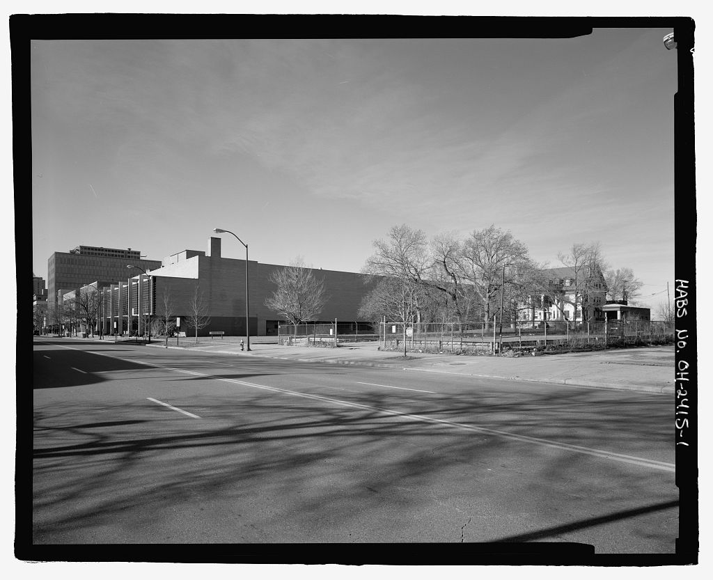
The AWT had served as the first wind tunnel in the United States for studying full-size aircraft engines in atmospheric conditions similar to those encountered during flight. In the late though, the facility shifted its focus to space and its interior was used as a large altitude chamber. The chamber was involved in several important tests for the Project Mercury Program. These included the guidance system for the Big Joe launch, posigrade and retrorockets, and the escape tower rockets. In addition, the seven Mercury astronauts and several test pilots came to the facility to train in a unique rotational test rig. SPC No. 1, which was added to the facility between and was among the first large vacuum chambers in the country that could simulate the environment of outer space. The SPC No.
1 vacuum tank was rivaled in size only by the smaller Mark I tank at the Arnold Engineering Development Center (AEDC). 10 The SPC s significance is directly linked to the success of the Centaur second-stage rocket (Fig. 9). The Centaur s original mission was to carry the Surveyor spacecraft to soft-land on the Moon and photograph the lunar surface in preparation for the Apollo Program. The SPC was directly involved with ten Centaur missions, but its testing influenced just about every subsequent mission. SPC No. 1 was used to conduct a series of long-term systems tests on a full-scale Centaur and nose-cone separation tests for multiple Surveyor missions. SPC No. 2 could simulate the conditions experienced in the upper levels of the atmosphere.
Some of this chamber s investigations included Atlas/Centaur (AC) separation tests, shroud jettison studies for the Orbiting Astronomical Observatory (OAO) missions, and a number of liquid-hydrogen propellant management studies. Centaur remained a successful workhorse, carrying Pioneer, Viking, Voyager, the OAOs, Cassini, and many other spacecraft. Topography The SPC was located on a portion of the original 200 acres acquired by the NACA from the Cleveland Municipal Airport in late for an engine research laboratory (the current location of NASA Glenn). The site had previously been used by the airport for parking and grandstands for the National Air Races. 11 The airport borders the laboratory on the east. The rest of the SPACE POWER CHAMBERS HAER No.
OH-133 Page 5 border loosely follows the Rocky River which bows to the northwest around the main campus. The river valley is densely forested, but the main portion of the property is flat and featureless. The SPC was built on a flat, featureless area at an elevation ranging from to above sea level. The nearby area contained several other laboratory buildings, including the Engine Research Building 5, ERB), the IRT and several small support buildings for the IRT. These original buildings had similar designs and finishes, giving the area a unified appearance (Fig. Original Construction The original design for the tunnel began in at the NACA Langley Memorial Laboratory and NACA Ames Aeronautical Laboratory.
The tunnel s distinctive shell, test section, and electrical drive system were designed at NACA Ames by Carl Bioletti, Walter Vincenti, John Macomber, and Manfred Massa. Most of the other components were engineered at NACA Langley by Al Young, Larry Marcus, Harold Friedman, and others. 12 The Sam W. Emerson Company was the prime contractor for the general construction work. They commenced the excavations for the facility in the spring of (Fig. 11) and completed the task by late December. 13 The construction of the Office and Shop Building was completed in September This was followed closely by the completion of Refrigeration and Exhauster buildings. 14 19 The Pittsburgh-Des Moines Steel Company fabricated and constructed the shell.
20 Planning for the refrigeration system started at NACA Langley in April but it was soon taken over by the Carrier Corporation. Carrier s cooling system for the AWT was the largest refrigeration system in the world. Carrier provided all the system s equipment and was then contracted to install the system. 21 The original control room, test section, and tunnel were completed in January and the facility ran its first test on February 4, 22 27 After fifteen years of wind tunnel use, center management decided that the facility would not be used for its airflow generation but for its large internal space and altitude simulating capabilities.
Although the decision to create the SPC would not be made for another two years, the first unofficial steps began between September and April The cooling coils, makeup air pipe, and turning vanes had been removed from the west end of the tunnel (Fig. An elevated walkway and banks of lights were erected along the western wall. A catwalk was erected along the ceiling of the western leg. In addition, the tunnel s interior was cleaned and repainted. Various fittings were installed on the floor and walls as part of several temporary test stands and setups. Over about one year beginning in April a gimballing system (the Multiple Axis Space Test Inertia Facility, MASTIF) was installed at the base of the tunnel s throat section (Fig.
This was a three-axis rig with a pilot s chair mounted in the center surrounded by three diameter cages. A two-level steel platform, used to enter and view the rig, was constructed around the rig. The top level of the platform was even in height with the test section and the lower level was approximately 3' above the tunnel floor. Starting in a number of steps were taken to convert the wind tunnel into two large test chambers (Figs. 14 to This included separating the chambers from each other, resealing the SPACE POWER CHAMBERS HAER No. OH-133 Page 6 outer shell, adding a removable dome, and upgrading the exhaust system for space simulation. In addition, the existing drive shaft, fan, turning vanes, and exhaust scoop were removed from the east end of the tunnel.
Three bulkheads were installed inside the tunnel to create the two chambers. The largest was the 31'-0"-diameter seal between structural ribs No. 70 and 69 near the southeast corner of the southern leg where the wind tunnel fan was located. 28 A section of the upper half of the tunnel near the southeast corner was cut out and removed with a crane. The crane was then used to install the large red bulkhead, one half at a time, in the opening. Another seal was created at the east end of the former test section, which completed sealing off the entire eastern leg of the tunnel for SPC No. 1. During the conversion process, the outer skin of the tunnel was removed to check the inner shell for leaks (Fig. Structural tests revealed that the entire SPC No. 1 chamber area had to be rewelded.
Some of those involved with the conversion felt that this was due to the original hurried wartime construction. The rewelding slowed down the conversion progress and drove up costs. 29 The insulation and outer shell were not reinstalled. Since the larger SPC No. 2 chamber would be used for upper atmospheric tests, it did not have to be rewelded, and the insulation and outer shell remained in place. The interior of the 30'-0"-diameter, 100'-0"-long SPC No. 1 was sandblasted and repainted with a double-coat of aluminum paint that would not outgas in a high vacuum. 30 The AWT s exhaust system was replaced by a new oil-diffusion-based system that could create a vacuum to 10 6 mm of mercury. 31 A new Vacuum Pump House was constructed underneath SPC No. 1 to house this new vacuum system (Fig.
The ten diffusion pumps were connected from below to the chamber floor. The Centaur rocket program was transferred to NASA Lewis in October just as the SPC was nearing completion. Center management decided that the new vacuum chamber would be an ideal place to study the behavior of the rocket s systems in a space environment. At this time, the SPC s most distinguishing trait, a 22.5'-0"-diameter cylindrical extension with a detachable dome (Fig. was created near the southeast corner. The extension was created in the ceiling of the chamber so that the full-size Centaur could be vertically positioned inside the chamber. The extension was capped with a removable dome so that the Centaur could be lowered inside by a crane.
32 Another 20'-0"-diameter bulkhead was inserted on the western end of the test section (Fig. 21) before the throat section. This, along with the 32 -0" seal in the southeast corner, created another test chamber SPC No. 2 in the remainder of the tunnel. 33 This large, J-shaped chamber was used for a number of Centaur shroud separation and propellant behavior tests. Previous test equipment, including the gimbal spin rig, was removed from the tunnel. Although the wind tunnel internals were removed and the walls were painted for the Project Mercury tests, the area was cleaned up and repainted for the new SPC chamber. The existing tunnel exhausters were sufficient for simulating the altitudes of the upper atmosphere at which shrouds would be jettisoned. 34 SPACE POWER CHAMBERS HAER No.
OH-133 Page 7 The clamshell lid for the former tunnel test section was removed, and a metal bridge and stairway into the tunnel were built at the east end of the test section. Steel-grated flooring was installed in the bottom of the test section. An overhead rail crane was mounted in the northeast leg to transfer articles from the test section in the high bay into SPC No. 1. A new control room for SPC No. 1, which sought to replicate the launch control room at Cape Canaveral, was created underneath the former tunnel test section (Fig. Instrumentation cables traveled from the east wall directly up to the dome. The existing wind tunnel control room was modified to run the tests in SPC No. 2. This primarily involved rewiring and altering the control panels.
Although the SPC was completed in September the modifications and setup for the Centaur Program pushed back the first tests for over a year. The first separation tests in SPC No. 2 began in October 10, The Centaur rocket was placed in SPC No. 1 on March 19, and environmental testing began that December. Surveyor separation tests began in SPC No. 1 during the interim in July Alterations The SPC facility did not undergo any major alterations during its operational period from to Various platforms, hooks, braces, and other temporary items were added to the interior for test setups. Some of these additions were left in place afterwards, but most were cut off near their bases. SPC No. 2 included an oval platform elevator (Fig.
23) that could be raised the entire height of the chamber on two vertical steel girders. The elevator s 11'-0"-diameter interior opening allowed it to be placed around the payload shrouds to assist in separation test preparations. 35 In an effort to test deceleration pellets for the new Zero Gravity Research Facility, a penetration was installed in the top of SPC No. 2 in late A 5'-0"-diameter, over 20'-0"-tall deceleration stand was mounted to the chamber floor. A temporary shacklike enclosure was built on the top of the tunnel to protect the accelerator apparatus. A tubular device extended to the deceleration bucket on the chamber floor. 36 The SPC control room and its Shop and Office Building were transformed into the MSL in the early This included the repurposing of the SPC No.
1 control room and sealing of the high-bay area. 2.2 Events History Project Mercury In response to the Soviet Union s launch of the Sputnik I and II satellites in President Eisenhower pushed for the creation of a civilian space agency. NACA Lewis, which had been working on rocket propulsion and high-energy fuels for years, was influential in the decision to base the new agency on the existing NACA laboratories. NASA officially came into being on October 1, and the NACA Lewis Flight Propulsion Laboratory became the NASA Lewis Research Center. The center underwent a major reorganization and for the next ten years concentrated its efforts almost exclusively on the space program. SPACE POWER CHAMBERS HAER No.
OH-133 Page 8 NASA s first step would be Project Mercury a series of twenty-one unmanned and seven single-person orbital flights. On October 15, the team coordinating Project Mercury, the Space Task Group met to allocate the testing assignments among the NASA centers. The AWT would be used extensively, but not as a wind tunnel. The tunnel s interior and altitude simulation would be utilized to test the Mercury/Atlas separation system, calibrate retrorockets, and test the attitude control system. The facility also was selected to study the escape tower rocket plume and to train astronauts how to bring a spinning capsule under control. 37 The first attempt to launch a capsule on a full-size Atlas booster was dubbed Big Joe.
Big Joe was a single mockup Mercury capsule without an escape tower, life support, or other systems. The flight was designed to simulate the reentry of the capsule without actually placing it in orbit and to test the launch and recovery processes. 38 NASA Lewis was asked to assemble the capsule and design the electronic instrumentation and automatic stabilization system. 39 The STG decided to forgo their original plans to use balloons and to instead employ the AWT to qualify the capsule and all its systems at high altitudes before launch. 40 The MASTIF was created inside the AWT to simulate the various motions the capsule would be subjected to.
During the early summer of qualifications, the attitude control and retrorockets were fired, and the capsule was exposed to simulated altitudes up to for long periods of time. 41 On September 9, Big Joe MA 1 was successfully launched on an Atlas D missile, and the mission objectives were achieved. 42 The Mercury capsule had six rockets on a retro-package affixed to the bottom of the capsule. Three of these were posigrade rockets used to separate the capsule from the booster, and three were retrograde rockets used to slow the capsule for reentry into Earth s atmosphere. There were several problems while the posigrade and retrograde rockets were being qualified, and there was no backup system if the retrograde braking system failed.
The STG assigned the task of resolving the issue to NASA Lewis and NASA Ames. 43 Full-scale separation tests using mockups of both the Redstone and Atlas boosters were conducted in the AWT at altitudes comparable to the upper atmosphere (Fig. The capsule s posigrade rockets were fired, and the capsule jettisoned forward on a tether. The AWT tests in January and February determined that a gas buildup in the Redstone ballast section actually accelerated the separation process. 44 Mercury/Atlas separation tests in mid-April ensured that the firing of the posigrade rockets did not injure any other components and determined the actual boost level of the posigrades. 45 Three Mercury retrorocket qualifications tests were also begun in April in the AWT (Fig.
A retrograde thrust stand was erected in the southwest corner of the tunnel. The studies showed that a previous problem of delays in igniting the propellant had been resolved. Follow-up test runs verified reliability of the coated igniter s attachment to the propellant grain. 46 In addition, the capsule s retrorockets were calibrated so that they would not alter the capsule s position when fired. 47 During late spring the AWT was used to determine whether the plume from the Mercury capsule escape tower rocket would engulf the capsule during an emergency separation from the booster. The escape tower was a steel rig and rocket attached to the nose of the Mercury SPACE POWER CHAMBERS HAER No. OH-133 Page 9 capsule.
The tower had its own propulsion system, which could be used to jettison the capsule to safety in the event of launch vehicle malfunction on the launch pad or at any point prior to separation from the booster. 48 The tunnel was evacuated to an altitude of approximately and the escape tower was mounted to the tunnel wall with a mockup Mercury capsule at the end. Three different escape tower motors were successfully fired. 49 One of the highest profile tests ever conducted in the AWT was the MASTIF (Fig. informally referred to as the gimbal rig. The MASTIF was a three-axis rig designed the previous year to test the Big Joe guidance system.
Modified with a pilot s chair mounted in the center, a control stick, and a mock control panel, the MASTIF was used during February and March to train the Mercury 7 astronauts on how to rein in a tumbling spacecraft. It was also used to study the effects of rapid rotation on the pilots eyesight. The rig was set up in the northwest corner of the tunnel. The pilot was strapped in on a foam couch in the center of the rig with only the arms free to operate communications and panic buttons and a stick that controlled the small nitrogen jets that ran the movement of the MASTIF. 50 Centaur Program Between and NASA Lewis refocused its efforts almost completely on the space program.
NASA Lewis built or reassigned nineteen space-related facilities during the Apollo Program and mothballed numerous aeronautics facilities. 51 With employees, Lewis had become the second largest NASA center by 52 It was during this rich period of growth that the Centaur second-stage rocket program, NASA Lewis s most important contribution to the space program, was transferred to Cleveland. Although it was designed solely for the Surveyor missions to explore the Moon s surface, Centaur went on to perform scores of missions. These included Pioneer, Viking, the Lunar Orbiter, OAOs, Cassini, and others. The AWT played a key role in resolving early problems with the Centaur.
The Centaur Program was created by the Department of Defense in but it shifted to the NASA Marshall Space Flight Center on November 8, 53 The first launch on May 8, failed shortly after lift-off because of a Centaur malfunction, and the program was on the verge of cancellation. NASA Marshall engineers had never felt comfortable with Centaur s nontraditional design or liquid-hydrogen propellant. NASA Lewis had been performing work with hydrogen and other nontraditional fuels for years and was confident in its safety and the advantages. In October the program was transferred to NASA Lewis. NASA Lewis was steadily building up space-related test facilities in Cleveland and at its satellite Plum Brook Station.
Among these were the two new large test chambers recently created inside the former AWT. One chamber could replicate an outer space environment and the other that of Earth s upper atmosphere. The new facility was officially renamed the SPC on September 12, 54 NASA Lewis s nuclear propulsion and power programs also were gearing up at this time, and SPC No. 1, the space tank, had actually been built to study the Systems Nuclear Auxiliary Power Program (SNAP 8) nuclear power generator. 55 Plans for the chamber were changed with the SPACE POWER CHAMBERS HAER No. OH-133 Page 10 transfer of the Centaur Program. Another year of construction was needed to add an extension and domed lid to SPC No. 1 to accommodate an upright Centaur (Fig.
Surveyor Nose Cone Tests The first studies in the new facility, however, were a series of AC separations (Fig. 28) conducted in SPC No. 2 during the fall of The simulated AC vehicle was hung horizontally in the large chamber. When the retrorockets fired, the Atlas model, which was on wheels, was jettisoned into a net. Researchers found that the firing of the eight retrorockets was inconsistent. Follow-up studies with standard and alternate versions of the rocket igniters firing at pressure altitudes up to revealed the causes of the unpredictability. The lighters were redesigned by the manufacturer and requalified in the In addition, the rockets were configured in such a way that the misfiring of one rocket would not mar the separation.
57 A new method of loading the propellant also was derived from these studies. The increased impulse significantly reduced the separation time, which reduced the danger of collision between the two stages during separation. 58 After successful launches of the Lewis-led AC 2 and AC 3, NASA Lewis researchers conducted a series of nose fairing tests in anticipation of the next Centaur launch scheduled for late which would attempt to place a mockup Surveyor spacecraft into orbit. Although ambient atmosphere separation tests prior to AC 3 were successful, the separation during the AC 3 launch had difficulties that nearly caused a mission failure. NASA engineers felt that the low pressure of space affected the bottle used to activate the explosive bolts. SPC No.
1 s space simulation could determine any design faults in the AC 3 fairing and flight-qualify the AC 4 shroud components (Figs. 29 and 59 The tests of the fairing were conducted in the northeast corner of SPC No. 1 from July 31 to November 24, with many high-speed cameras installed. After numerous modifications and adjustments, NASA Lewis researchers determined that internal jet expansion separation devices could successfully jettison the fairing without damaging the payload. It was also determined that these separation tests must be conducted in a vacuum environment. 60 All modifications implemented between the AC 3 and AC 4 missions were verified in the As a result, AC 4 was the first Centaur mission to have an error-free shroud jettison.
61 Despite the fact that the fiery failure of AC 5 was caused by the booster engines, modifications had been made to the Centaur and the nose cone that required requalification of the shroud. This flight qualification of the new shroud was conducted from May to July in SPC No. 1. These studies tested the nose cone design, determined the impact on the payload envelope, and studied the shroud s effect on the new, thinner Centaur fuel tanks. 62 Although the payload envelope had to be altered, NASA Lewis researchers approved the entire nose fairing design and load limits for flight. 63 The successful mission of AC 6 (Fig. 31) on August 11, restored NASA s confidence in the Centaur s capabilities.
Centaur Environmental Testing During the buildup to the Surveyor flights, NASA Lewis researchers wanted to determine how the Centaur s auxiliary propulsion, hydraulic, pneumatic, and electrical systems behaved in a space environment. Of particular concern was the effect of the heat from the electronics on the SPACE POWER CHAMBERS HAER No. OH-133 Page 11 cryogenic liquid-hydrogen propellant. A Centaur 6A rocket was flown to Cleveland on a C 130 aircraft and transported via flatbed truck to the SPC shop area in October (Fig. For several months, General Dynamics personnel worked with NASA Lewis researchers as they studied and began reassembling the rocket in shop area.
The 6A model had to be reharnessed electronically and updated to properly replicate the Centaur that would be performing the AC 4 mission. 64 On March 19, the Centaur was rolled out of the shop. A crane lifted the lid off the dome, then lifted the rocket into the air and lowered it into a test stand inside the chamber (Fig. SPC No. 1 sought to replicate all aspects of outer space except microgravity and meteor impingements. The new oil diffusion pumps pulled the vacuum down to a pressure level of 10 5 mm of mercury. 65 The cold temperature was supplied by a nitrogen-filled cold wall erected around the Centaur (Fig. The radiation of space was created using banks of quartz lamps. In addition, a pneumatic system rotated the rocket s RL 10 engines as they would be during flight.
66 After the proper vacuum was achieved in the tank, the rocket was brought to launch temperature, the electrical system was turned on, and the test commenced. The first three minutes of the test were the Atlas booster phase. The Centaur systems were activated immediately afterward the simulated separation. This involved prestarting the Centaur s RL 10 engines, engine ignition and cutoff, coasting for approximately twenty-five minutes, a second engine firing and cutoff, payload separation, Centaur course reversal, and finally the shutdown of all Centaur systems by ground-based operators. 67 After the AC 4 tests, the rocket was reharnessed in the AC 8 configuration. In all, there were twenty to thirty test runs conducted over several years.
Every aspect of the test was intended to be identical to actual flight, down to minutiae like the ink used to mark wires. 68 These studies verified the trustworthiness of Centaur s basic design and proved that the electrical system could perform during a two-burn flight in a space environment. The few design problems that were discovered, such as the electrical inverter and C-band transponder, were rectified before the Surveyor flights. 69 Among these was the recommendation not to use pressurized electronics canisters, and avoiding overheating by maintaining the minimal necessary power level. 70 Propellant Management Studies The SPC also was utilized for several liquid-hydrogen management tests such as the Weightlessness Analysis Sounding Probe (WASP) and Centaur hydrogen vent studies.
The WASP was a two-stage sounding rocket designed by the NASA Lewis Spacecraft Technology Division to examine the control of liquid-hydrogen propellant during the periods between rocket firing, as on the two-burn Centaur flights. The WASP rocket would carry a transparent fuel tank and television cameras to film the behavior of the propellant during flight. 71 The WASP s shroud underwent testing in the SPC in August and April (Fig. On June 7, the WASP rocket was successfully launched off of Wallops Island with intentional sloshing of the liquid hydrogen. 72 The almost seven minutes of microgravity during freefall from provided researchers enough data to launch AS 203 in July 73 SPACE POWER CHAMBERS HAER No.
OH-133 Page 12 The December AC 4 and April AC 8 missions were designed as propellant management studies. When the first engine burn ended on AC 4, the liquid hydrogen sloshed forward, resulting in the venting of some of the hydrogen in liquid rather than gas. The propellant s motion and resulting inability to maintain the vehicle s balance while gases were being vented off skewed the Centaur s trajectory, causing additional liquid venting and tumbling. Approximately ninety percent of the liquid hydrogen was lost, and the engines could not be restarted resulting in a failed mission. The failed AC 4 mission demonstrated that engine shutoff, coasting, and restarting forces influenced the propellant s behavior.
Although research programs like Aerobee had previously studied the behavior of liquid hydrogen on scaled models, the AC 4 flight revealed the unique issues created by the forces associated with full-size propellant systems. 76 NASA Lewis researchers undertook a series of propellant management studies (Fig. 36) that resulted in several modifications for the AC 8 flight. These included a baffle in the hydrogen tank to prevent sloshing, energy dissipaters, and a redesign of the vent system. The new system underwent extensive qualification and vent valve performance tests in SPC No. 2. 77 On the AC 8 mission, the propellant was successfully managed and off- gasses were expelled without altering the rocket s trajectory.
78 Larger Shroud Testing The SPC also was used for a series of Centaur and Agena nose-cone separation tests for the OAO missions. The OAO satellites were designed by the NASA Goddard Space Flight Center to study and retrieve ultraviolet data on specific stars and galaxies that Earth-bound and even atmospheric telescopes could not view because of ozone absorption. 79 The OAO satellites were direct predecessors of the Hubble Telescope. 80 The instrumentation and payload were covered by a nose cone as the rocket traveled through the atmosphere. The nose cone was then ejected once the vehicle was in space. SPC No. 2 was used because it was not necessary to simulate space since the nose cone separation occurred in the upper atmosphere.
The existing exhausters were strong enough to reach that level. 81 In addition, the nose fairing was larger than the Surveyor fairings, and the extra room in SPC No. 2 was needed. A steel base, in diameter, was installed on the floor at the center of the chamber. A metal spacer was attached to the base, and a mock Centaur forward bulkhead was attached to the spacer. The fairing and payload were then mounted to the forward bulkhead. A x nylon net was horizontally secured above the chamber floor to catch the fairing halves after they were jettisoned. 82 The first OAO satellite with its four experiments would be the heaviest payload yet carried by the Atlas/Agena D. 83 During the summer of the shroud was tested three times in SPC No. 2 at altitudes of twenty miles.
Accelerometers on the model and shroud provided researchers with data that could verify a successful separation during the actual launch. 84 The April 8, OAO 1 launch and separation went smoothly, but a battery failure caused the mission to fail within ninety minutes. 85 After the failed first Agena-OAO mission, NASA management decided to replace the Agena with the more powerful Centaur rocket; however, the basic Agena separation system and nose SPACE POWER CHAMBERS HAER No. OH-133 Page 13 cone were retained. The 40'-0"-long modified nose fairing for the OAO 2 mission was longer than the AC Surveyor nose fairing, and it was jettisoned by a mechanical spring rather than by a gas thruster system. 86 In April three OAO nose fairing setups were successfully jettisoned in SPC No.
2 at a simulated altitude of (Fig. 87 OAO 2 was launched on AC 16 on December 7, and after only a month, it obtained over twenty times the amount of ultraviolet data from stars than from all of the sounding rocket studies over the previous fifteen years combined. 88 The next OAO mission, OAO B, failed on November 30, when the nose fairing did not separate properly. 89 Although not used to test the shroud before the launch, the SPC was a principle element of the failure investigation. Tests in SPC No. 2 during April led to a redesigned single-piece fairing. 90 In April and May a full-scale version of this new OAO nose cone underwent a series of successful jettison tests in SPC No. 2 (Fig. OAO C, or Copernicus, launched by AC 22 on August 21, remained an active observatory for eight years.
91 2.3 Contemporary Vacuum Chamber Facilities Vacuum Chamber Development As humans began flying aircraft at greater elevations, there were an increasing number of attempts to create ground-based facilities to test the behavior of both humans and aircraft components in altitude conditions. In general, altitude conditions were simulated with vacuum chambers, which reduce the air pressure inside the tank. These chambers are containers that achieve low pressure or vacuum by using exhausters or pumps to remove the air and other gases. For basic altitude simulation, air pressure and temperature have to be controlled, but humidity and air density may also be factors. There are many different types and sizes of vacuum chambers used for a variety of different purposes.
In the aerospace test facility field, there are two basic variations. The first are smaller test cells used for altitude engine testing, such as the Propulsion Systems Laboratory at NASA Glenn or the T cells at the AEDC. The second are the large vacuum chambers used to study flight hardware in a space environment, such as NASA Glenn s Space Power Facility and NASA Marshall s Space Environment Simulation Laboratory (SESL). The AWT falls into the former category, and the SPC falls into the latter. The first controlled demonstration of a vacuum dates back to Italy in After inverting a sealed mercury tube and lowering it into a pool of mercury, Evangelista Torricelli became the first person to maintain a vacuum.
By observing that the mercury in the tube did not run out, he surmised that air in the tube had a weight and its exertion of pressure on the mercury in the pool kept the mercury in the tube elevated. This demonstration led to a series of bell jar vacuum experiments in the 92 With the advent of aircraft in the early twentieth century, manufacturers sought ways to test the engines in altitude conditions. The first altitude test beds in the were built at high elevations. Frequent inclement weather and the relatively low altitudes dampened the effect of these facilities. The Zeppelin Works created at Friedrichshafen in south Germany may be the SPACE POWER CHAMBERS HAER No. OH-133 Page 14 first vacuum chamber designed specifically to test aircraft engines.
It was used for the engines for the Zeppelin airships. Almost simultaneously, the National Bureau of Standards created an altitude chamber for engines in the United States. Hobart Cutler Dickinson was instrumental in the design of the Liberty aircraft engine at the onset of World War I and became head of the NBS aeronautical powerplant section. In this role, Dickinson designed and operated the nation s first altitude chamber for testing full-scale aircraft engines. The simulated chamber was constructed by the NBS at the request of the NACA. 93 It made its first test run on December 26, with a Liberty 8 engine.
94 In the the Italian city of Guidonia added a test bed that could simulate altitudes up to In the Germans created a similar test facility capable of partially simulating altitudes of A second facility at Rechlin also controlled the inlet temperature down to 60 C and a pressure altitude of The first real German altitude chamber was the Herbitus facility built in Munich during It was an actual tank in which refrigerated air was ducted to the engine inlet, the exhaust gas was cooled, and the tank was evacuated to a pressure altitude of At the end of the war, the facility was seized by American troops. The Herbitus was considered the first altitude test bed for jet engines. It was dismantled and reassembled at the AEDC.
NACA Altitude Chambers The NACA s AERL in Cleveland, Ohio, used the vacuum concept to lower the air pressure to simulate high altitudes in the AWT in The wind tunnel used exhausters to create a vacuumlike atmosphere and remove combustion gases. The AWT could operate full-scale engines in conditions that replicated the speed, altitude, and temperature of actual flight. Two altitude test cells were built inside the AERL s ERB during the mid-1940s to alleviate the AWT s workload. This facility, referred to as the Four Burner Area, contained two static chambers into which full-size engines could be installed and run at altitudes up to and temperatures ranging from 200 to minus seventy degrees Fahrenheit.
An even larger pair of test chambers, the was added in Similar facilities, such as the Ordnance Aerophysics Laboratory in Texas, were built in the The late brought not only increasingly larger and faster engines, but more importantly the advent of the space age. Initial missions in the late revealed that the behavior of engines, flight systems, and hardware was affected by the conditions encountered in space. The AWT s altitude simulation was used during and for a number of Project Mercury tests at pressure altitudes up These did not use the tunnel s airflow, just its diameter and its 163'-long western leg and the exhauster pumps. In McDonnell created a 30'-0"-diameter vacuum chamber at its St. Louis location.
The effort, referred to as Project Orbit, subjected the Mercury capsule to simulated missions in the chamber altitudes up to Soon afterward, a more powerful altitude test chamber was constructed in Hanger S at Cape Canaveral. When completed, altitude pressure would simulate The chamber, a vertical cylinder with domed ends, was in diameter and high. The chamber was designed to allow a partial spacecraft functional check in a near-vacuum SPACE POWER CHAMBERS HAER No. OH-133 Page 15 environment. Construction was completed in April The first simulated orbital mission, with the Mercury spacecraft in the altitude chamber, was conducted on April 95 These were useful tools but were limited by their size.
In it was decided to increase the AWT s vacuum capabilities and to permanently construct two test chambers within the tunnel shell one capable of simulating the altitudes of outer space, the other of Earth s upper atmosphere. The facility was renamed the It was originally intended to study a full-scale SNAP 8 nuclear space power conversion system. At the time, there were no tanks of that size that could produce such a deep vacuum in the United States. By the end of when the SPC was completed, there were nine large vacuum chambers.
Many others would emerge by Although larger chambers capable of deeper vacuums would later be constructed, the rapid conversion of the AWT into a space tank allowed the 31'-0"-diameter, 100'-0"-long tank to play a vital role in the early years of the space program. There were two major tanks that became operational in the Aerospace Environmental Chamber known as Mark I at the AEDC and the two chambers in the SESL at what is today the NASA Johnson Space Center. The 35'-0"-diameter, 65'-0"-long Mark I tank was slightly wider than the SPC but not as long. The 65'-0"-diameter, 120'-0"-tall Chamber A at the SESL was built specifically to test the Apollo capsule. It was significantly larger than the SPC and could create high altitudes.
Like Mark I, the SESL s Chamber B was wider than the SPC but not as long. 96 At NASA Lewis in the Director Abe Silverstein continued to seek better facilities to test flight hardware and propulsion systems in space environments. An auxiliary site called Plum Brook Station was used to build a test reactor and a number of large space test facilities. The two most impressive were the B 2 Space Propulsion Facility (now a National Historic Landmark) and the massive The SPF remains the world's largest thermal vacuum chamber, measuring in diameter and high (Fig. It has been used extensively to test rocket payload fairings, various systems for the International Space Station, and planetary landing systems, such as those developed for the Mars Exploration Rovers.
In March NASA announced that the SPF would be used to perform integrated environmental testing of the Orion crew exploration vehicle. The tests will simulate environmental conditions such as those the Orion will experience during launch, in-orbit operations, and reentry. 97 In Hughes Space and Communications Company added a 63,000-cubic-foot, dual-capacity thermal vacuum chamber to its massive Integrated Satellite Factory in Los Angeles. The facility can conduct four thermal vacuum tests at space altitudes, five near-field antenna tests, and two thermal stress tests.
98 3.0 Architectural Information The SPC contained NASA Lewis s first and only large vacuum chamber for testing flight hardware from until it was superseded by the SPF at Plum Brook Station in The SPC was located inside the former AWT (Fig. which was among the first group of structures built at the NACA AERL in the The SPC contained two altitude test chambers within the tunnel shell. SPACE POWER CHAMBERS HAER No. OH-133 Page 16 The SPC s supporting infrastructure included the Shop and Office Building, the Vacuum Pump House, the Refrigeration Building, and Cooling Tower No. 1.
All of these structures were built in the immediate vicinity of the The SPC s central location allowed it to easily work in conjunction with several other facilities and buildings, including the hangar, the ERB, and the The tunnel, which contained the two chambers, was a massive rectangular structure long on the north and south legs, and long on the east and west sides. The 20'-0"-diameter former tunnel test section, which served as the main entranceway to the two test chambers, was contained in the rear test chamber room of the Shop and Office Building. The courtyard inside the tunnel loop was approximately 40' wide at the east end, 18' at the west end, and long. 99 3.1 SPC No. 1 The high-vacuum SPC No. 1 (Fig.
which was created in the east leg of the tunnel, had an internal volume of cubic feet and a length of The chamber was in diameter at the southeast end and in diameter at the northeast end. 100 A 22.5'-0"-diameter cylindrical extension with a removable dome was inserted in the ceiling to create of vertical space within the chamber (Figs. 42 and 101 SPC No. 1 could create the conditions found at an altitude of 100 miles so that researchers could study how spacecraft would behave in outer space. The chamber was connected to the center s central air system, which could evacuate the chamber to an altitude of Two piston pumps further thinned the air, and the final vacuum was brought down by ten oil diffusion pumps located below the chamber.
The complex setup in the chamber could replicate all aspects of space except microgravity and meteors. A nitrogen-filled cold wall, which enveloped the spacecraft, supplied the cryogenic temperatures of space, and six banks of quartz lamps simulated solar radiation. In addition, a hydraulic system caused the rocket s RL 10 engines to rotate as they would during flight. A tanking system was used to keep the balloonlike fuel tanks partially filled, and a wide array of telemetry was installed. The tests were operated and monitored in a control room that resembled the actual launch pad controls. Unlike the vacuum tank in SPC No. 1, SPC No. 2 did not require a major overhaul for it to be used as a high-altitude test chamber.
The existing AWT exhauster and refrigeration systems were powerful enough to achieve the desired altitudes up to Shell The original tunnel was composed of a 1"-thick inner steel shell with fiberglass insulation over it and a thinner outer steel covering. The outer covering and insulation were permanently removed during the creation of SPC No. 1. The inner steel alloy shell was rewelded and sealed to withstand the decreased pressures that the chamber would be subjected to. The two large corner rings and thirty-one tunnel support rings jutted out from the shell. The sealing of SPC No. 1 was particularly important to creating a vacuum comparable to that found in space.
One of the most pressing problems during the creation of the tank was the poor welds that were made during the hurried World War II construction of the tunnel. Small plastic SPACE POWER CHAMBERS HAER No. OH-133 Page 17 bags were placed over each weld and filled with helium, and a helium leak detector was used to analyze how much helium leaked through each of the welds and penetrations. 102 The entire SPC No. 1 shell was rewelded at a considerable expense. Coating of the tunnel with a protective gray paint appears to have ceased in the mid-1990s. SPC No. 1 s shell appears to have suffered less rust damage than the thin protective steel covering the rest of the facility (Fig.
Dome and Extension The dome, installed between the and ring on the eastern leg of the tunnel, provided a 45'-0"-high area inside the chamber. 103 The top of the dome was elevated from the tunnel shell. The dome sat atop a vertical base that extended from the top of the tunnel (Fig. This steel base had steel fins radiating from its perimeter that corresponded to the tunnel s support rings. Around the top of the base was a steel support band. 104 The exterior sides of the dome contained nine 32"-diameter circular portals that extended outside of the dome. 105 Two of the dome s ports permitted electrical connections to heater panels inside the chamber. 106 The lower panels were powered through ports near the bottom of the chamber.
The wires from the dome were guided through the chamber and into the SPC No. 1 control room in the Shop and Office Building by two cable trays. An elevated catwalk erected around the dome allowed access to the instrumentation portals and cable trays. From this catwalk, a small ladder and a stairway of four metal steps was built to allow access from the dome base to the top of the cap. A small fixed ladder connected the catwalk to a grated footbridge running northwest. This bridge joined the existing walkway along the top of the tunnel s northeast leg. A series of light fixtures were placed along the catwalk and pathway. The walkway that originally ran along this portion of the tunnel was removed during the conversion to the vacuum chamber.
The dome was capped by a 22.5'-0"-diameter lid that was approximately high (Figs. 46 to 107 The lid had a flat circular top area with a vent pipe and a sealed stove pipe in the center. There also were three eyehooks to secure cables used for lifting. This top area was surrounded by metal handrails, and there were four grated steps with handrails leading from the edge of the lid to its top. 108 When the lid was in place, a ring around the lid was welded to a ring around the chamber opening. This permitted both a solid seal and the ability to break the seal when the cap had to be removed. 109 Interior Walls The interior walls were primarily smooth with few obstructions or penetrations besides the dome in the ceiling and the ten vents in the floor for the diffusion pumps.
The corner rings were flat surfaces that were relatively flush with the walls. There were a series of flood light fixtures mounted along the upper portions of the walls with cable trays just below (Fig. The floor had a large number of fixed eyehooks and other fittings that were used for various test setups in the There was a monorail crane track down the middle of the ceiling. The former wind SPACE POWER CHAMBERS HAER No. OH-133 Page 18 tunnel drive shaft penetration that had been sealed in was almost flush with the eastern wall. During the conversion process from wind tunnel to altitude chamber, rust, scale, and engine exhaust pollutants were sandblasted from the interior of the tunnel. The new chamber was then sealed with a double-coat of aluminum paint.
110 In the walls and ceiling showed some signs of rust but were in fairly good condition (Fig. The floor, however, had suffered a great deal of rust and water damage (Fig. especially underneath the dome. This had been caused by rain entering through the unsealed access portals around the dome. Bulkheads SPC No. 1 was sealed from the rest of the tunnel by bulkheads at the southwest and northwest portions of the chamber. The larger, 31'-0"-diameter convex bulkhead at the southwest consisted of a circular metal plate at its center with twelve triangular pieces of steel radiating from it (Fig. A 24"diameter viewing port was located several feet below the center plate.
111 The 27'-0"-diameter bulkhead at the north end of the chamber contained three access ports on each side and a 15'-0"-diameter door (Figs. 53 and 54) in the middle. The door was braced by two horizontal metal beams across its upper portion, and it had dual O-ring seals. 112 An overhead pulley with a thick steel chain was used to open and shut the door. Nitrogen inlet and outlet connections were installed on chevron baffle chambers. 113 The access ports were aligned vertically on each side of the door. The north side had three 18" instrumentation ports (Fig. 55) with aluminum face plates. The south side had two of the same and an 18"-diameter viewing port with a polished plate glass face. The plates were buried between 12" and 27" into the bulkhead away from the chamber.
114 Crane An overhead 4000-pound rail crane (Fig. 56) was installed in SPC No. 1. It ran west a short distance in the northwest corner, then curved and ran southward along the chamber ceiling to the southwest corner. 115 Because of the 15'-0"-diameter access door in the northern bulkhead, a platform with steps had to be constructed inside the chamber (Fig. This platform was approximately above the floor and stretched the entire width of the bulkhead. The stairs had dual handrails, and the platform had posts across the front with chain as a railing. 3.2 Vacuum Vacuum System The vacuum system was the primary element in SPC No. 1 s ability to simulate a space environment.
During the conversion of the tunnel to a space tank, the existing pumping system was replaced by a new oil-diffusion-based system. Ten diffusion pumps (Fig. 58) and several roughing pumps were installed in the new Vacuum Pump House building underneath SPC No. 1 (Fig. The empty chamber could be evacuated to 10 6 mm of mercury. SPACE POWER CHAMBERS HAER No. OH-133 Page 19 The vacuum was brought down slowly in several phases to prevent excessive airflow over the pumps. The center s central exhauster system could evacuate the tank to pressure altitude in about fifteen minutes. The two piston pumps would simultaneously remove cubic feet per second of air during the roughing stage. 116 A rotary positive displacement pump would then remove air at 500 cubic feet per second.
The final vacuum was pulled down by the ten diameter oil diffusion pumps (Fig. which could remove cubic feet per second of air. The entire process took about twenty-four hours, but the chamber could be returned to sea level almost instantly using a gaseous nitrogen system. 117 Vacuum Pump House The new pumps were housed in the 12'-0"-high, 46'-0.875"-long, and 20'-1"-wide structure built directly underneath SPC No. 1 (Figs. 61 to The main portion of the Vacuum Pump House actually used the bottom of the chamber as its roof. The front north side had a sloping roof high at its lower edge. The east side of the building had a pedestrian door near the center and ventilation louvers further northward. The west side had identical louvers.
The north side had a single pedestrian door and rectangular louvers. The south end had a double set of pedestrian doors. A hood connected the sides of the main structure to the bottom of the wind tunnel. 118 The pump house had ten 32"-diameter oil-diffusion pumps lined in pairs that were capable of pumping cubic meters per second. An 18"-diameter pipe joined the pumps and connected them to a Roots-Connersville vacuum blower pump in the northwest corner that were capable of pumping 850 cubic meters per minute and to two Stokes 3/2 H mechanical vacuum pumps in the northeast corner. 119 Since the chambers have been idle, this structure had been used for storage by the Educational Services Division.
It was demolished during the demolition of the tunnel in 3.3 Centaur Systems Test Setup Besides the addition of the dome and extension to the SPC No. 1 vacuum tank, there were several other modifications made specifically for the environmental testing of the full-sized Centaur rocket. These included components to simulate the temperatures of space, general setup and work equipment, and infrastructure to power and operate the spacecraft. Centaur 6A Rocket The Centaur that was used for the SPC No. 1 tests was an early 6A model with thinner fuel tanks than later versions (Fig. This Centaur was used for static engine tests in Sycamore Canyon, California, and launch site integration tests at Cape Kennedy.
It was originally intended to be used for the follow-up to the AC 2 flight, but a renovation of the launch pad delayed the launch. 120 The Centaur was removed and transported to Cleveland, and another Centaur was eventually launched. The 28.5'-0"-long, 10'-0"-diameter Centaur 6A had two Pratt & Whitney RL 10 15,000-pound- thrust engines that rotated to steer the rocket. During the coast periods, hydrogen peroxide engines on the aft side maneuvered the rocket. 121 The Centaur had two balloon-type propellant tanks. The electronics and control systems were at the forward section of the rocket, and the mechanical and propulsion systems were near the rear. The electronics package was located just SPACE POWER CHAMBERS HAER No.
OH-133 Page 20 below the payload and above the Centaur s forward bulkhead. A fiberglass fairing shielded the electronics and payload during the launch. The cryogenic propellant tank was shielded by insulation panels until the spacecraft exited the atmosphere. Platform The Centaur rested in an approximately 9'-tall triangular stand (Fig. 67) that sat on the chamber floor below the dome. The stand had a circular metal band approximately 18" wide in the middle into which the rocket was inserted. This band was supported at its edges by steel beams arranged in two triangular shapes. This entire structure was elevated approximately 6' by three struts. Two stretch towers inside the chamber supported the Centaur vertically and kept the spacecraft from collapsing on itself.
A large moveable platform was constructed along the floor of SPC No. 1 that allowed technicians access to the Centaur setup. The circular platform was in diameter and surrounded the vertically standing Centaur. 122 The platform ran along the east and west walls of the chamber on 30"-high metal rails. 123 Cold Wall A large liquid-nitrogen-cooled copper baffle was erected around the entire Centaur setup to simulate the cold temperatures of outer space (Figs. 68 and The radiant heat absorption device was designed specifically for these tests. The canisterlike cold wall was in diameter and rose high into the dome. The dome lid actually contained the top of the baffle.
The baffle had liquid-nitrogen-filled ribs, or bottles, that ran vertically the length of the Centaur and was painted black on the interior to attract heat. 124 These bottles had to be welded together using the new heliarc technique, which involved welding on copper. The success of this process was crucial because any nitrogen leaks would break the desired vacuum level. 125 A thermal siphon was used to draw cryogenic liquid nitrogen into the vertical ribs. The liquid nitrogen was stored in three 7000-gallon tanks stored outside of the chamber and pumped into the baffle through penetrations in the dome and near the rocket s base. The pressurization was remotely managed from the control room.
The nitrogen flowed through a separation tank, which contained a float switch that automatically kept the cold wall filled. A basin was placed underneath the cold wall to trap any cryogenic fuels that leaked from the wall or engines. 126 Heater Panels A radiant heater system was designed specifically for these Centaur tests to simulate the effect of the Sun s heat on the rocket systems. Certain lamps could be turned on at different times to recreate the changing areas where the rocket would be exposed to sunlight during a mission. Six sectors of tungsten-iodine lamps (Fig. 70) were arranged around the Centaur to simulate solar radiation.
Four of these arrays were on the upper end of the Centaur one contained twenty-three lamps at the payload adapter and three contained ninety-one lamps that surrounded the entire forward portion of the vehicle. Two arrays with 145 lamps were located near the RL 10 engines. 127 SPACE POWER CHAMBERS HAER No. OH-133 Page 21 Telemetry The Centaur telemetry in SPC No. 1 comprised six subsystems (Fig. These included a strong system for powered flight and a lower power system for coast periods. Camera and data transmission systems were installed to view the liquid-hydrogen tank. Ground support equipment controlled and monitored the Centaur. 128 Extensive instrumentation, including 200 transducers and eighteen landlines, were used to record the data in the offsite receiving station.
The recorded data were edited down at a later date. A number of K-logger chart-recording systems were used to record up to forty different parameters. A television camera, which was controlled and viewed in the SPC control room, was mounted near the lower section of the Centaur. 129 A cable rack ran vertically next to the Centaur inside the chamber and exited through a portal in the dome. This rack carried the vehicle s thermocouple lines and other wiring to the control room below the former wind tunnel test section. 130 Pneumatic System The Centaur had thin fuel tanks that required pressurization to retain their proper form. If the pressure difference between the upper section of the vehicle and the lower portion with the fuel tanks changed, the vehicle would likely collapse.
A pneumatic system was installed in SPC No. 1 to maintain this pressure differential at all times. The oxidant pressure was maintained at eight to ten pounds per square inch above the internal fuel tank pressure, which was kept at four to six pounds per square inch higher than the chamber pressure. 131 Hydraulic System The Centaur s RL 10 engines were hydraulically rotated as they would be during a flight but were not fired for the SPC tests. Their boost pump rotors were secured, and the propellant lines were sealed. 132 All fluid and air lines were hooked up to quick disconnects, and all the vents and valves were ducted outside of the chamber. Redundant, parallel electric systems were installed to ensure continuity during the tests.
133 Liquid-Hydrogen Supply The Centaur used liquid oxygen as an oxidizer and liquid hydrogen as a propellant. Since the Centaur s engines were not fired during the SPC No. 1 tests, it was not necessary to use liquid oxygen. Instead, the oxidizer tank was filled with liquid nitrogen. Because of its density in comparison to hydrogen, the tank was only filled ten percent with the nitrogen. 134 Liquid hydrogen was supplied to SPC No. 1 through a pumping system that penetrated the lower south wall of the chamber. A large liquid-hydrogen dewar was stored on railroad ties beneath the chamber, and additional dewars could be added using tanker trucks. 135 Figure 72 shows the control panel used to control this system. 3.4 SPC No. 2 Not including the area used for SPC No.
1 or the former tunnel test section, the remainder of the tunnel was converted into a larger, but less powerful, vacuum chamber. This J-shaped chamber ran from the southeast corner, through the south leg, through the west leg, and through the throat SPACE POWER CHAMBERS HAER No. OH-133 Page 22 section; it stopped just to the west of the test section (Fig. The diameter of the longer section in the south leg was approximately 33' at its east end and 51' at the west. The diameter of the throat section in the north leg narrowed from at the west to at the east. The widest section was the 121'-0"-long, 51'-0"-diameter west leg. 136 Shell The shell for SPC No.
2 was the original wind tunnel shell built in the A 1"-thick steel alloy similar to the current ASTM 710 Grade A3 steel plate was used to endure the low temperatures of the high-altitude environment. This alloy was covered with fiberglass insulation and a second, thinner steel shell to protect against the weather. 137 Coating of the facility with a protective gray paint appears to have ceased in the mid-1990s. Rust began to appear on the exterior of the tunnel by and was extensive by In recent years, the outer shell on the top of the tunnel would bow under human weight. Top of the Tunnel A series of stairs, ladders, and platforms were installed on the top of the tunnel in the to allow access (Fig. These had steel handrails that were approximately 3' high and segmented by a horizontal bar.
138 Interior Walls Although sections of the area that would be SPC No. 2 had been cleaned and repainted a few years prior for the Project Mercury tests, the area was cleaned and repainted again during the conversion to the The corner rings were flat surfaces that were relatively flush with the walls. These were 42" across at their midpoints and widened to 48" at the floor. The walls were smooth but did contain a number of obtrusions, particularly in the large western leg where the majority of the SPC No. 2 tests took place. In later years, a 15" x 74" rectangular hole was cut into the lower western wall. The 51'-0"-diameter western leg (Figs.
75 and 76) had a number of former cooling lines and two large makeup air lines that were capped on its western wall in to This area also had many fittings and modifications because of the Project Mercury tests and the tests performed in SPC No. 2. One metal work platform with handrails was mounted to the lower interior wall, and another was mounted to the center of the exterior wall. These work areas were added or removed depending on the test being conducted. However, several small toe stairs that had been created in the tunnel wall leading up to the platform areas remained. Other sets of this type of stairs were added on the interior northwest corner ring (Fig. 77) and on the exterior western wall leading up to longer elevated catwalk along the wall.
The steel-grated catwalk ran virtually the entire length of the section at the chamber s approximate vertical midpoint. Banks of floodlights were installed on the wall over the catwalk. Access was provided near the northwest corner by the set of seven toe steps that led to a small steel platform. From this platform, a fixed ladder led up to the catwalk. 139 SPACE POWER CHAMBERS HAER No. OH-133 Page 23 There were a number of fittings welded to the floor in the western leg. These included four 4"-diameter cuplike fittings 54" apart from one another that were arranged in a square pattern in the center of the area. Fourteen 10"-long, 3.5"-diameter tubular fittings were welded to the floor.
Ten of these ran in a row north and south, one was on the south end, and three more were on the north end. These were used to tighten the nets for the shroud separation tests. Large test articles were brought through a removable bulkhead at the junction of the tunnel s throat section and test section. A new squirrel hole access portal (Fig. 78) was created in the northern leg near the northwest corner of the tunnel in early to allow personnel into the chamber for the MASTIF tests. In recent years, this provided the only entrance into the chamber. The squirrel hole entrance was a 8'-8"-long, 48"-diameter tube that ramped from the exterior of the tunnel into the wide section. The interior opening was 58" wide, 82" high, and surrounded by a slight concrete collar.
The exterior opening had a steel lip with bolt holes around it. The tube had a hand rail and steel floor treads. A short set of metal stairs provided access to this entrance from the exterior (Fig. 140 The former tunnel throat section, which narrowed the tunnel s diameter from to had a 20-step metal stairway from the chamber floor to a platform level with the test section. An industrial private automatic exchange (PAX) telephone was mounted on a pole at the base of these steps for the MASTIF tests. A small metal platform was mounted to the inner wall at the top of the stairs. A 16-step stairway led to a small platform along the northern wall. A steel ladder rose from this platform to a catwalk (Fig. 80) that ran overhead through the western leg for the Project Mercury tests.
This catwalk was shortened during the creation SPC No. 2. Several steel-grated platforms were mounted to the curved walls of the interior wall of the throat section (Figs. 81 and These were installed or removed depending on the test being conducted. The northern steps, catwalk, and platforms were permanently removed years ago. The interior of the south leg (Figs. 83 and 84) of SPC No. 2 had few obtrusions except several eyehooks welded to the lower walls near the west corner. In recent years, several rectangular holes had been cut into the lower half of the tunnel walls; these revealed the insulation, mesh, and outer shell. There were two T-bars set up near the bulkhead in the southeast corner with the cross bar being approximately 36" high.
Figure 85 shows a hoist box installed on the inner wall. In the overall condition of the interior of the chamber was fairly good considering it had not been maintained in over thirty years. The walls did have some rusting, particularly near the southeast corner and along the seams. The welds at the support ring seams had been numbered with spray paint in recent years. Bulkheads SPC No. 2 was sealed off from SPC No. 1 by a bulkhead (Fig. 86) near the southeast corner. This bulkhead was painted red on the SPC No. 2 side and bowed into the chamber. A 24"-diameter viewing port approximately 24" from the chamber floor allowed researchers to look into SPC No. 1. 142 SPACE POWER CHAMBERS HAER No. OH-133 Page 24 SPC No. 2 was sealed off on the other end by a 20'-0"-diameter bulkhead (Fig.
87) between the throat section and the former wind tunnel test section. This concave bulkhead had an approximately 3'-deep lip around it that expanded into the throat section and a flat diameter plate. Elevator SPC No. 2 included an oval platform elevator on vertical steel girders that could be raised the entire height of the chamber (Fig. The elevator s interior diameter allowed the structure to be placed around payload shrouds to assist in separation test preparations. 143 The steel girders were mounted to the chamber floor and secured to the ceiling. Pulleys at the top of the shafts were attached to weights at the bottom. Cameras were set up on top of each post to film the separations, and an enclosed metal ladder ran the length of the southern post. 144 Cranes SPC No.
2 had two overhead monorail cranes. The first was a westward-sloping crane (Fig. 89) installed in the throat section for the Project Mercury tests. It was suspended from the chamber ceiling by six pairs of struts and a cross beam. Within the throat section, this crane had a second track that veered to the south, providing access to areas near the inner wall. The second crane (Fig. 90) ran along the SPC No. 2 ceiling the length of the western leg, then curved and traveled several feet into the south leg. This crane had a handheld control box that hung from the track. Figures 91 and 92 show tie downs and a net for a shroud separation test in SPC No. 2 and equipment mounted on an interior wall, respectively.
3.5 Space Power Chambers Building The former Shop and Office Building, renamed the Space Power Chambers Building in contained offices, a high bay, a shop area, two control rooms, and other support for the work being conducted in the The building was originally constructed in the to support the wind tunnel, but many of its functions were transferred to the SPC in the early Control Room for SPC No. 1 A new control room to operate SPC No. 1 was constructed in the balance chamber underneath the former tunnel test section. Efforts were made to make this control room as much like the Centaur launch controls at Cape Canaveral as possible. 145 The 23'-7.25"-wide, 20'-11.75"-long room went through the bulkhead that separated the tunnel s balance chamber from the rest of the building.
146 Access was provided through the mezzanine level of the SPC Building. The arrangements of the control panels (Fig. 93) made the room s interior appear octagonal. The eastern section (Fig. 94) had the vehicle pressure and tanking controls (Fig. hydrogen peroxide, hydraulic, stretch, pneumatic, and canister purge systems; the baffle and vacuum systems; and a solar simulator temperature monitor. The northern section consisted of tempera- ture and pressure monitors, electrical power controls and monitor, signal conditioning, and a solar simulator temperature monitor. SPACE POWER CHAMBERS HAER No. OH-133 Page 25 The western wall contained the guidance system, C band system, Azusa radar interferometer tracking system, nose cone, and vent valve monitors.
The southern section had data and event recorders (Fig. and radiofrequency and range safety monitors. The center of the room had two racks of control panels running parallel north and south. The eastern rack contained the test conductor controls, ground programmer, vehicle power monitor and flight control, and engine controls. The western rack contained data recorders manufactured by Brush Instruments. The exterior of the octagonal setup was a walkway with minor pieces of equipment, including telephones, air conditioners, and gas detectors. 147 The original air lock into the test section on the second floor was removed in 148 At this time, this section of the building went under a major renovation.
The stairs were bolstered, walls were repainted, a suspended acoustical ceiling was installed, and office areas were modernized. The SPC No. 1 control room was remodeled and used as the Far-Field Antenna Test Facility. 149 The control room area is now used as a small laboratory for antenna testing. It was not affected by the demolition of the tunnel in SPC No. 2 Control Room The former wind tunnel control room was converted into the control room for the tests in the SPC No. 2 altitude chamber (Figs. 97 to This primarily involved rewiring the telemetry and updating the control panels. The tunnel s floor-mounted pneumatic engine controls were removed. The panels ran east and west along the south wall of the room.
The original acoustic tiles on the walls and ceiling remained, as did the overhead fluorescent light fixtures. The eastern panel controlled the exhaust flow from SPC No. 2, SPC No. 1, the the ERB, and the cooler. These areas were laid out schematically on the panel with toggle switches and indicator lights. The next panel operated the liquid-nitrogen system. It consisted of thirteen clock-faced dials and many tank pressurization controls. The panel at the west end contained a large number of controls for cameras inside SPC No. 2. SPACE POWER CHAMBERS HAER No. OH-133 Page 26 4.0 Index of Space Power Chambers Photographs Many C-numbered photographs are available from NASA s or NASA Glenn s image archives: NASA Image eXchange (NIX, http://nix.nasa.gov/) GRC ImageNet Page Figure 1.
SPC with SPC No. 1 to the left and SPC No. 2 occupying the rest of the tunnel, 37 Figure 2. NASA Lewis Research Center with the SPC left of center (viewed from the northwest), 37 Figure 3. Location map for the SPC 7), (OH_Cuyahoga_Space-Power- Chambers_003). 38 Figure 4. SPC complex, showing SPC No. 1 (left) and SPC No. 2 (right), 39 Figure 5. SPC with Solar Power Laboratory (left), Shop and Office Building (center), and Refrigeration Building (right), (OH_Cuyahoga_Space-Power- Chambers_005). 40 Figure 6. Interior of SPC No. 1, 40 Figure 7. Centaur environmental test setup, (OH_Cuyahoga_Space-Power- Chambers_007). 41 Figure 8. Demolition plan for the AWT. Areas of the SPC that were demolished are indicated by hash marks, 42 Figure 9.
NASA Lewis researcher being interviewed in the SPC shop area in front of the Centaur rocket, 42 Figure 10. NASA Lewis, showing the Cleveland Municipal Airport (left), the Rocky River valley (right), and the city of North Olmsted (background) (viewed from the northeast), 43 Figure 11. Original construction of the east leg of the AWT and future SPC No. 1, 44 Figure 12. Project Mercury escape tower rocket test in the AWT after the vanes and cooling coils were removed, 44 Figure 13. Installation of the gimbal rig near the AWT throat section with the vanes and makeup air nozzle removed, (OH_Cuyahoga_Space-Power- Chambers_013). 45 Figure 14. Plans for removal of the AWT fan, air scoop, and turning vanes for the 46 Figure 15.
Bulkhead section being lifted into the opening cut in the southeast corner of the tunnel, 47 Figure 16. Bulkhead installed in the southeast corner of the tunnel (viewed from the west), 47 Figure 17. Outer steel layer of the wind tunnel being removed so that the inner layer could be rewelded to create a higher vacuum seal, (OH_Cuyahoga_Space- Power-Chambers_017). 48 SPACE POWER CHAMBERS HAER No. OH-133 Page 27 Figure 18. Interior of SPC No. 1 prior to the addition of the dome, showing diffusion pump portals in the floor, 49 Figure 19. SPC No. 1, showing the Vacuum Pump House, bulkheads, and flooring in the former tunnel test section, (OH_Cuyahoga_Space-Power- Chambers_019). 49 Figure 20. Extension and dome created near the southeast corner of SPC No. 1 (viewed from the west), 50 Figure 21.
Southwest corner of SPC No. 2 being renovated after the Project Mercury tests, 50 Figure 22. Construction of the control room for the SPC underneath the former wind tunnel test section, 51 Figure 23. Platform elevator around the Centaur payload inside SPC No. 2, 52 Figure 24. Mercury capsule/Redstone booster separation test inside the AWT, 53 Figure 25. Mercury capsule retrorocket test setup inside the AWT, 54 Figure 26. John Glenn prepares for a test in the Multiple Axis Space Test Inertia Facility (MASTIF) inside of the AWT, (OH_Cuyahoga_Space-Power- Chambers_026). 55 Figure 27. SPC No. 1 with extension and dome for the Centaur rocket, 56 Figure 28. The first tests in the SPC were a series of AC separation studies in SPC No. 2, 56 Figure 29.
Surveyor nose cone during tests in the northeast corner of SPC No. 1 for the AC 4 mission, 57 Figure 30. SPC No. 1 setup for Surveyor nose cone separation tests, 57 Figure 31. Surveyor shroud qualification for the AC 6 mission in the northeast corner of SPC No. 1, 58 Figure 32. Centaur 6A being inspected in the SPC shop area prior to insertion into the chamber, 58 Figure 33. Cutaway of SPC No. 1 showing the installation of the Centaur rocket, 59 Figure 34. Nitrogen-filled cold wall high and in diameter) assembled around the Centaur in SPC No. 1, (OH_Cuyahoga_Space-Power- Chambers_034). 60 Figure 35. WASP shroud jettison test setup in the northeast corner of SPC No. 1, 61 Figure 36. Hydrogen vent rig installed in SPC No.
2 following the failure of the AC 4 flight because of sloshing, 62 Figure 37. Modified Agena shroud being tested with a Centaur model in SPC No. 2 for OAO 2, 63 Figure 38. Redesigned single-piece shroud being tested in SPC No. 2 for use on the OAO C mission, 64 SPACE POWER CHAMBERS HAER No. OH-133 Page 28 Figure 39. Inside the SPF at NASA Glenn s auxiliary Plum Brook Station, 65 Figure 40. SPC complex in the former AWT (viewed from the south), 66 Figure 41. SPC No. 1 in the east leg of the former AWT (viewed from the south), 67 Figure 42. SPC No. 1 extension and dome (viewed from the west), 68 Figure 43. Interior of SPC No. 1 with an opening for the dome at the top and pump penetrations on the floor (viewed from the north), (OH_Cuyahoga_Space- Power-Chambers_043). 69 Figure 44. SPC No.
1 shell to the right with the original tunnel outer shell to the left showing heavy rust damage, 70 Figure 45. SPC No. 1 with its extension, dome, and surrounding walkways (viewed from the northeast), 71 Figure 46. SPC No. 1 dome showing its base, instrumentation portals, and lid (viewed from the north), 71 Figure 47. Crane removing the lid from the SPC No. 1 dome (viewed from the east), 72 Figure 48. SPC No. 1 lid being lowered to the ground by a crane, 72 Figure 49. SPC No. 1 interior with the extension and dome at the top and the cable tray along the wall (viewed from the north), (OH_Cuyahoga_Space-Power- Chambers_049). 73 Figure 50. SPC No. 1 dome and lid (viewed from inside the chamber), 74 Figure 51. SPC No.
1 floor showing water damage and numerous fittings from tests (viewed from the south), 74 Figure 52. 31'-0"-diameter bulkhead at the south end of SPC No. 1 (viewed from the east), 75 Figure 53. Inside SPC No. 1 bulkhead with a swinging door in the center and ports on the sides (viewed from the east), (OH_Cuyahoga_Space-Power- Chambers_053). 75 Figure 54. Former test section of SPC No. 1 bulkhead with its door closed (viewed from the west), 76 Figure 55. Close-up of one of the instrumentation ports in the north SPC No. 1 bulkhead, 76 Figure 56. 4000-pound monorail crane along the center of the SPC No. 1 ceiling, 77 Figure 57. Platform inside SPC No. 1 that provided access to the doorway in the bulkhead, 77 Figure 58. Close-up of one of ten diffusion pump openings in the floor of SPC No.
1, 78 Figure 59. Test chamber vacuum system and dry air bleed system, 78 SPACE POWER CHAMBERS HAER No. OH-133 Page 29 Figure 60. Diffusion pump openings in SPC No. 1 during its conversion to a vacuum tank, 79 Figure 61. Interior of Vacuum Pump House and its diffusion pumps below SPC No. 1 (viewed from the north), 79 Figure 62. Rear of Vacuum Pump House beneath SPC No. 1 (viewed from the southeast), 80 Figure 63. Vacuum Pump House elevations and sections drawings, 81 Figure 64. Construction of Vacuum Pump House beneath SPC No. 1, 82 Figure 65. Exterior of the Vacuum Pump House under SPC No. 1 (viewed from the northeast), 82 Figure 66. Centaur 6A rocket readied in SPC shop before testing in SPC No. 1, 83 Figure 67. Stand that supported the Centaur rocket being lifted into SPC No.
1, 84 Figure 68. The nitrogen separation tank setup to left of the dome supplied the cold wall inside with coolant, 85 Figure 69. Nitrogen cold wall placed around the Centaur that absorbed radiant heat to create cryogenic temperatures, (OH_Cuyahoga_Space-Power- Chambers_069). 86 Figure 70. View up the side of the Centaur showing a group of tungsten lamps in the foreground, 87 Figure 71. Telemetry connections between SPC No. 1 and the control room, 88 Figure 72. Control panel in SPC control room for the tanking system, 89 Figure 73. Exterior of SPC No. 2 (aerial view from the north), 89 Figure 74. South leg of SPC No. 2 with walkway on top (viewed from the south), 90 Figure 75. 51'-0"-diameter western leg of SPC No.
2 with a catwalk along the outer wall (viewed from the north), (OH_Cuyahoga_Space-Power- Chambers_075). 90 Figure 76. Western leg of SPC No. 2 with crane, elevator stands, and platforms against the walls (viewed from the south), (OH_Cuyahoga_Space-Power- Chambers_076). 91 Figure 77. Corner ring with the western leg of SPC No. 2 in the foreground (viewed from the southwest), 92 Figure 78. Interior view of squirrel hole entrance into SPC No. 2, 92 Figure 79. Interior and exterior of the access door built into the north wall of SPC No. 2, 93 Figure 80. Throat section of SPC No. 2 showing overhead crane and catwalk (viewed from the east), 94 SPACE POWER CHAMBERS HAER No. OH-133 Page 30 Figure 81. Throat section of SPC No. 2 with the bulkhead at the far end (viewed from the west), 95 Figure 82.
Throat section of SPC No. 2, showing steps and a telephone in the foreground (viewed from the west), (OH_Cuyahoga_Space-Power- Chambers_082). 95 Figure 83. South leg of SPC No. 2 (viewed from the east), 96 Figure 84. South leg of SPC No. 2 (viewed from the west), 96 Figure 85. Hoist box installed on the inner wall just prior to the throat section, 97 Figure 86. 31'-0"-diameter bulkhead near the southeast corner of SPC No. 2 (viewed from west of SPC No. 2), 97 Figure 87. 20'-0"-diameter bulkhead near the west end of the former test section (viewed from west of SPC No. 2), (OH_Cuyahoga_Space-Power- Chambers_087). 98 Figure 88. Platform elevator in SPC No. 2 lifted above Centaur model (viewed from the north), 99 Figure 89.
Overhead crane and its two rails (viewed from east of the throat section), 100 Figure 90. Crane in western leg of SPC No. 2 near the southwest corner (viewed looking up), 101 Figure 91. Tie downs and net strung across SPC No. 2 to catch the shroud during the separation test, 101 Figure 92. Equipment mounted to the interior wall near the throat section, 102 Figure 93. Southern wall in SPC No. 1 control room with various event monitors, 103 Figure 94. Control panels on the east wall of the SPC No. 1 control room, 103 Figure 95. Panels for the Centaur tanking system in the southeast corner of the SPC No. 1 control room, 104 Figure 96. Data recorders in the western rack in the center of the SPC No. 1 control room, 104 Figure 97. SPC No.
2 control room with the airflow control panel in foreground (viewed from the east), 105 Figure 98. Interior of SPC No. 2 control room with the control panel on the left (viewed from the east), 106 Figure 99. SPC No. 2 control room (viewed from the west), 106 SPACE POWER CHAMBERS HAER No. OH-133 Page 31 5.0 References 1 Finished Grading Plan for Area Bounded by Roads B, C, & D, in NASA Glenn Central Drawing Files (Cleveland, Ohio: NACA AERL, drawing ED 1. 2 AERL Construction Report No. 66, (Cleveland, Ohio: NASA Glenn History Collection, Directors Collection, 3 Charles Herman, AERL Construction Report No. January 1, (Cleveland, Ohio: NASA Glenn History Collection, Directors Collection, box 3 of 5, 4 AERL Construction Report No.
(Cleveland, Ohio: NASA Glenn History Collection, Directors Collection, 5 Charles Herman, AERL Construction Report No. August 28, (Cleveland, Ohio: NASA Glenn History Collection, Directors Collection, box 3 of 5, 6 AERL Construction Report No. November 8 13, (Cleveland, Ohio: NASA Glenn History Collection, Directors Collection, 7 AERL Construction Report No. (Cleveland, Ohio: NASA Glenn History Collection, Directors Collection, 8 Harold Friedman, interview by Robert S. Arrighi, Beachwood, Ohio, November 2, (Cleveland, Ohio: NASA Glenn History Collection, Oral History Collection). 9 Virginia Parker Dawson, Engines and Innovation: Lewis Laboratory and American Propulsion Technology (Washington, DC: NASA SP App.
B, accessed June 4, 10 Hollingsworth, A Survey of Large Space Chambers (Washington, DC: NASA TN D 12, accessed June 13, http://ntrs.nasa.gov 11 City Gets Plane Lab. Cleveland Plain Dealer, November 25, 12 Ernest G. Whitney, Lecture 22 Altitude Wind Tunnel at AERL (Cleveland, Ohio: NASA Glenn History Collection, Altitude Wind Tunnel Collection, June 23, 1. 13 Contract Between the NACA and the Sam W. Emerson Co. for Construction of Several Units of the AERL. NA (Cleveland, Ohio: NASA Glenn History Collection, Altitude Wind Tunnel Collection), 6. 14 AERL Construction Report No. 66. 15 Herman, AERL Construction Report No. 16 AERL Construction Report No. 17 Herman, AERL Construction Report No. 18 AERL Construction Report No. 19 AERL Construction Report No.
20 Engine Research Wind Tunnel Office and Shop Building First Floor Plan (October 30, drawing ED 205 (previously D 21 Friedman, interview by Arrighi, Beachwood, Ohio, November 2, 22 AERL Construction Report No. 66. 23 Herman, AERL Construction Report No. 24 AERL Construction Report No. 25 Herman, AERL Construction Report No. 26 AERL Construction Report No. 27 AERL Construction Report No. 28 Vacuum Test Chamber for AWT, General Plan, Elevations, and Shell Details (Cleveland, Ohio: NASA Lewis Research Center, May drawing CF SPACE POWER CHAMBERS HAER No. OH-133 Page 32 29 Friedman, interview by Arrighi, Beachwood, Ohio, November 2, 30 John Povolny, Space Simulation and Full-Scale Testing in a Converted Facility (Washington, DC: NASA Report N66 2.
31 AWT Gets New Assignment, Orbit, January 12, 32 Ralph F. Schmiedlin et al., Flight Simulation Tests of a Centaur Vehicle in a Space Chamber (Cleveland, Ohio: NASA TM X 10, accessed June 13, http://ntrs.nasa.gov 33 Povolny, Space Simulation, 1. 34 Howard Wine, interview by Robert S. Arrighi, Sept. 4, (Cleveland, Ohio: NASA Glenn History Collection, Oral History Collection). 35 Charles W. Eastwood, Centaur Orbiting Astronomical Observatory Nose Fairing Altitude Jettison Test (Washington, DC: NASA TM X 1. http://ntrs.nasa.gov 36 Space Power Vacuum Chamber, Chamber Modifications for Deceleration Test (Cleveland, Ohio: NASA Lewis Research Center, October drawing CF 37 Maxime A.
Faget, Chief, Flight Systems Division, memorandum to Project Director, Status of Test Work Being Conducted at the Lewis Research Center in Conjuction With Project Mercury, October 22, in Project Mercury: A Chronology. Part II(A), Research and Development Phase of Project Mercury, October 3, through December James M. Grimwood (Washington, DC: NASA SP accessed June 17, 38 Project Mercury Congressional Report (Cleveland, Ohio: NASA Glenn Research Center Film, accessed June 17, 39 Lloyd S. Swenson, James M. Grimwood, and Charles C. Alexander, This New Ocean: A History of Project Mercury (Washington, DC: NASA SP ch. 9, sec. 3, accessed June 17, 40 Mark Wade, Mercury Balloon Flight Tests. Astronautix, Accessed March 41 Swenson, Grimwood, and Alexander, This New Ocean, ch. 6, sec. 6.
42 Grimwood, James M.: Project Mercury: A Chronology. Part II(A), Research and Development Phase of Project Mercury, October 3, through December NASA SP 43 Swenson, Grimwood, and Alexander, This New Ocean, ch. 9, sec. 5. 44 F.E. Miller et al.: The Mercury-Redstone Project (Washington, DC: NASA George C. Marshall Space Flight Center, NASA TM X 4 7. 45 Faget, memo to Project Director. 46 NASA Space Task Group, Project Mercury (Quarterly) Status Report No. 6 for Period Ending April 30, in Project Mercury: A Chronology. Part II(B), Research and Development Phase of Project Mercury, October 3, through December James M. Grimwood (Washington, DC: NASA SP accessed June 17, 47 Faget, memo to Project Director.
48 Project Mercury Familiarization Manual Louis, Missouri: McDonnell Aircraft SEDR 104 3, June 21, 6 3. 49 NASA Space Task Group, Project Mercury. 50 Astronauts at Lewis, Orbit, February 19, 51 Eugene Manganiello, memorandum to I.H. Abbott and E.W. Conlon at NASA Headquarters, Curtailment of Research Areas and Facilities for Fiscal Year January 20, SPACE POWER CHAMBERS HAER No. OH-133 Page 33 52 Lewis Research Center, NASA Lewis Research Center press release, January 17, 53 72 The First Decade of Centaur, Lewis News, October 20, 54 Abe Silverstein, Updating the Name of Structure Number 7 of the Lewis Research Center (Cleveland, Ohio: NASA Lewis Research Center memo, September 12, 55 AWT Gets New Assignment. 56 Richard W.
Heath et al., Investigation of Atlas Solid Fuel Retarding Rocket During Atlas- Centaur Separation Tests (Washington, DC: NASA TM X 1, accessed June 17, http://ntrs.nasa.gov 57 Larry Ross, interview by Robert S. Arrighi, March 1, (Cleveland, Ohio: NASA Glenn History Collection, Oral History Collection). 58 72 The First Decade of Centaur. 59 Jack C. Humphrey, Centaur AC 4 Nose Fairing Jettison Tests (Washington, DC: NASA TM X 1, accessed June 17, http://ntrs.nasa.gov 60 Humphrey, Centaur AC 4, 1. 61 Povolny, Space Simulation, 53. 62 Jack Humphrey and Charles Eastwood, Centaur AC 6 Nose Fairing Separation Tests (Washington, DC: NASA TM X 1, accessed June 17, http://ntrs.nasa.gov 63 Humphrey and Eastwood, Centaur AC 6, 1. 64 Ross, interview by Arrighi, March 1, 65 AWT Gets New Assignment.
66 Lewis Launch Record Is Near Perfect, Lewis News, November 24, 4. 67 Schmiedlin et al., Flight Simulation, 14. 68 Ross, interview by Arrighi, March 1, 69 Schmiedlin et al., Flight Simulation, 1. 70 Schmiedlin et al., Flight Simulation, 1. 71 Lewis Launches Wasp, Lewis News, June 24, 8. 72 Lewis Launches Wasp, 8. 73 Courtney G. Brooks, James M. Grimwood, and Loyd S. Swenson, Chariots for Apollo: A History of Manned Lunar Spacecraft (Washington, DC: NASA SP ch. 8, sec. 2, Qualifying Missions, accessed June 17, 74 Raymond F. Lacovic et al., Management of Cryogenic Propellants in a Full-Scale Orbiting Space Vehicle (Washington, DC: NASA TN D 1, accessed June 17, http://ntrs.nasa.gov 75 William A.
Groesbeck, Design of Coast-Phase Propellant Management System for Two-Burn Atlas-Centaur Flight AC 8 (Washington, DC: NASA TM X 2, accessed June 17, http://ntrs.nasa.gov 76 Groesbeck, Design of Coast-Phase Propellant, 2. 77 Groesbeck, Design of Coast-Phase Propellant, 15. 78 Lacovic et al., Management of Cryogenic Propellants, 1. 79 Walter H. Scott, The Engineering Design of the Orbiting Astronomical Observatory, in The Observatory Generation of Satellites Session II of a Special Astronautics Symposium held at the Franklin Institute, Philadelphia, Dec. 27, during the Annual Meeting of the American Association for the Advancement of Science (Washington, DC: NASA SP 30, 54 61, accessed June 17, http://ntrs.nasa.gov SPACE POWER CHAMBERS HAER No.
OH-133 Page 34 80 Linda Neuman Ezell, NASA Historical Data Book: Volume III, Programs and Projects (Washington, DC: NASA SP ch. 3, accessed June 17, 81 Wine, interview by Arrighi, Sept. 4, 82 Eastwood, Centaur, 8 83 Large Load for Atlas-Agena, Lewis News, April 1, p. 1. 84 OAO Tests Here, Lewis News, September 3, 4. 85 OAO B Launch November 17, NASA Lewis Research Center press release 70 October 29, 86 Staff of Lewis Research Center, Atlas-Centaur AC 16 Flight Performance Evaluation for the Orbiting Astronomical Observatory OAO II Mission (Washington, DC: NASA TM X 6, accessed June 18, http://ntrs.nasa.gov 87 Eastwood, Centaur, 1. 88 OAO Meets Milestone, Lewis News, January 31, 2. 89 OAO Failure, Lewis News, December 18, 3. 90 New Shroud Is Ordered, Lewis News, July 2, 3.
91 Ezell, NASA Historical Data Book: Volume III, ch. 3. 92 Egidio Festa, ed., Evangelista Torricelli, Institute and Museum of History of Science, Florence, Italy, accessed March 93 Biographies: Several Prominent Scientists and Engineers Spearheaded the Development of the Guarded-Hot-Plate Apparatus, NIST Virtual Museum. Reprinted from the Journal of the Washington Academy of Sciences, 40 94 Dickinson and Boutell, The Altitude Laboratory for the Test of Aircraft Engines (Washington, DC: NACA TR 44, accessed June 18, http://ntrs.nasa.gov 95 Mark Wade, Mercury. accessed March 96 Lori C.
Walters, To Create Space on Earth: The Space Environment Simulation Laboratory and Project Apollo (Washington, DC: NASA/CR accessed June 18, http://ntrs.nasa.gov 97 Jan Wittry, World s Largest Vacuum Chamber to Test Orion, NASA Glenn Research Center, last modified June 19, 98 Hughes Opens World s Largest Satellite Factory, Hughes Space and Communications Company press release, March 18, accessed June 18, 99 Engine Research Laboratory Wind Tunnel General Plan (Moffett Field, California: NACA Ames Aeronautical Laboratory, June drawing EX 100 Demolition of Building #7: Altitude Wind Tunnel. General Arrangement Plan, AWT Base Bid/Option 3 (Cleveland, Ohio: NASA Glenn Research Center, drawing ED 101 Schmiedlin et al., Flight Simulation, 10. 102 Wine, interview by Arrighi, Sept.
4, 103 Testing of the Centaur Stage in the Space Power Chamber, Details of Neck Opening Cover and Access Platforms (Cleveland, Ohio: NASA Lewis Research Center, drawing CF 104 Ladder, Rail Space Power Chamber. Engineering Products Inc. NAS3 Contract 10 V 5 11 (Pittsburgh, Pennsylvania: Pittsburgh Des Moines Steel Company, May 15, SPACE POWER CHAMBERS HAER No. OH-133 Page 35 105 Testing of the Centaur, drawing CF 106 Testing of the Centaur Stage in the Space Power Chamber, Power Bus Details for Forward Heater Panels (Cleveland, Ohio: NASA Lewis Research Center, February drawing CF 107 Ladder, Rail Space Power Chamber. 108 Testing of the Centaur, drawing CF 109 Schmiedlin et al., Flight Simulation, 9. 110 Povolny, Space Simulation, 2.
111 Vacuum Test Chamber, drawing CF 112 Schmiedlin et al., Flight Simulation, 9. 113 Vacuum Test Chamber for AWT, 15 0 Diameter Door (Cleveland, Ohio: NASA Lewis Research Center, May drawing CF 114 Vacuum Test Chamber for AWT, Structural Details of 18" and 24" Viewing Ports and 18" Instrumentation Ports (NASA Lewis Research Center, May drawing CF 115 Vacuum Test Chamber for AWT, Test Chamber Details (Cleveland, Ohio: NASA Lewis Research Center, May drawing CF 116 Schmiedlin et al., Flight Simulation, 35 and 39. 117 Humphrey, Centaur AC 4, 3.
118 Environmental Testing of the Centaur Stage in the Space Power Chamber, Vacuum Pumping System (Cleveland, Ohio: NASA Lewis Research Center, February drawing CF 119 Vacuum Test Chamber for AWT, Vacuum Pump House Elevations and Sections (Cleveland, Ohio: NASA Lewis Research Center, May drawing CF 120 Schmiedlin et al., Flight Simulation, 12 and 39. 121 Schmiedlin et al., Flight Simulation, 30. 122 Testing of Centaur Stage in Space Power Chamber, Liquid Nitrogen Baffle Work Platform and Support Towers (Cleveland, Ohio: NASA Lewis Research Center, April drawing CF 123 Vacuum Test, drawing CF 124 Schmiedlin et al., Flight Simulation, 12 and 35. 125 Wine, interview by Arrighi, Sept. 4, 126 Schmiedlin et al., Flight Simulation, 12 and 35. 127 Schmiedlin et al., Flight Simulation, 12 and 35.
128 Schmiedlin et al., Flight Simulation, 10. 129 Schmiedlin et al., Flight Simulation, 12 and 35. 130 Space Power Chambers, Centaur Environmental Test, Electrical Cable and Cable Support Plan and Elevations (Cleveland, Ohio: NASA Lewis Research Center, November drawing CF 131 Povolny, Space Simulation, 48. 132 Schmiedlin et al., Flight Simulation, 30. 133 Povolny, Space Simulation, 49. 134 Schmiedlin et al., Flight Simulation, 12. 135 Testing of Centaur Stage in Space Power Chamber, General Area Arrangement and Piping Distribution (Cleveland, Ohio: NASA Lewis Research Center, August drawing CF 136 Engine Research Laboratory, drawing EX 137 John Victory, New NACA Wind Tunnels, Aero Digest, August 1, SPACE POWER CHAMBERS HAER No.
OH-133 Page 36 138 Altitude Wind Tunnel Access Ladders and Platforms General Plan and Details. ED NACA AERL drawing, June 139 Martin Brown, Centaur Project Tunnel Modification (Cleveland, Ohio: NASA Lewis Research Center, July 25, photograph C accessed June 18, 140 AWT New Access Opening at Rings No. 8 9 (Cleveland, Ohio: NASA Lewis Research Center, January 26, drawing CD 141 Martin Brown, Centaur Project Tunnel Modification (Cleveland, Ohio: NASA Lewis Research Center, July 25, photograph C accessed June 18, 142 Vacuum Test Chamber, drawing CF 143 Eastwood, Centaur, 1. 144 John Marton, Spacecraft Clearance Gauges for Orbiting Astronomical Observatory OAO in Space Power Chamber SPC No.
2 (Cleveland, Ohio: NASA Lewis Research Center, photograph C accessed June 18, 145 Ross, interview by Arrighi, March 1, 146 Space Power Chambers Office and Shop Building, First Floor Plan (Cleveland, Ohio: NASA Lewis Research Center, September drawing CD 147 Centaur Environmental Test. Control Room Plan View and Personnel Layout (Cleveland, Ohio: NASA Lewis Research Center, October drawing CD 148 Modification for New Far Field Antenna Test Lab in Building No. 7, Demolition Plans (Cleveland, Ohio: NASA Lewis Research Center, March 8, drawing CF 149 Modification for New Far Field Antenna Test Lab in Building No. 7, Plans: First and Second Floor (Cleveland, Ohio: NASA Lewis Research Center, March 8, drawing CF SPACE POWER CHAMBERS HAER No. OH-133 Page 37 Appendix Figures and Images Figure 1.
SPC with SPC No. 1 to the left and SPC No. 2 occupying the rest of the tunnel, Figure 2. NASA Lewis Research Center with the SPC left of center (viewed from the northwest), SPACE POWER CHAMBERS HAER No. OH-133 Page 38 Figure 3. Location map for the SPC 7), SPACE POWER CHAMBERS HAER No. OH-133 Page 39 Figure 4. SPC complex, showing SPC No. 1 (left) and SPC No. 2 (right), SPACE POWER CHAMBERS HAER No. OH-133 Page 40 Figure 5. SPC with Solar Power Laboratory (left), Shop and Office Building (center), and Refrigeration Building (right), Figure 6. Interior of SPC No. 1, SPACE POWER CHAMBERS HAER No. OH-133 Page 41 Figure 7. Centaur environmental test setup, SPACE POWER CHAMBERS HAER No. OH-133 Page 42 Figure 8. Demolition plan for the AWT.
Areas of the SPC that were demolished are indicated by hash marks, Figure 9. NASA Lewis researcher being interviewed in the SPC shop area in front of the Centaur rocket, SPACE POWER CHAMBERS HAER No. OH-133 Page 43 Figure 10. NASA Lewis, showing the Cleveland Municipal Airport (left), the Rocky River valley (right), and the city of North Olmsted (background) (viewed from the northeast), SPACE POWER CHAMBERS HAER No. OH-133 Page 44 Figure 11. Original construction of the east leg of the AWT and future SPC No. 1, Figure 12. Project Mercury escape tower rocket test in the AWT after the vanes and cooling coils were removed, SPACE POWER CHAMBERS HAER No. OH-133 Page 45 Figure 13.
Installation of the gimbal rig near the AWT throat section with the vanes and makeup air nozzle removed, SPACE POWER CHAMBERS HAER No. OH-133 Page 46 Figure 14. Plans for removal of the AWT fan, air scoop, and turning vanes for the SPACE POWER CHAMBERS HAER No. OH-133 Page 47 Figure 15. Bulkhead section being lifted into the opening cut in the southeast corner of the tunnel, Figure 16. Bulkhead installed in the southeast corner of the tunnel (viewed from the west), SPACE POWER CHAMBERS HAER No. OH-133 Page 48 Figure 17. Outer steel layer of the wind tunnel being removed so that the inner layer could be rewelded to create a higher vacuum seal, SPACE POWER CHAMBERS HAER No. OH-133 Page 49 Figure 18. Interior of SPC No.
1 prior to the addition of the dome, showing diffusion pump portals in the floor, Figure 19. SPC No. 1, showing the Vacuum Pump House, bulkheads, and flooring in the former tunnel test section, SPACE POWER CHAMBERS HAER No. OH-133 Page 50 Figure 20. Extension and dome created near the southeast corner of SPC No. 1 (viewed from the west), Figure 21. Southwest corner of SPC No. 2 being renovated after the Project Mercury tests, SPACE POWER CHAMBERS HAER No. OH-133 Page 51 Figure 22. Construction of the control room for the SPC underneath the former wind tunnel test section, SPACE POWER CHAMBERS HAER No. OH-133 Page 52 Figure 23. Platform elevator around the Centaur payload inside SPC No. 2, SPACE POWER CHAMBERS HAER No. OH-133 Page 53 Figure 24.
Mercury capsule/Redstone booster separation test inside the AWT, SPACE POWER CHAMBERS HAER No. OH-133 Page 54 Figure 25. Mercury capsule retrorocket test setup inside the AWT, SPACE POWER CHAMBERS HAER No. OH-133 Page 55 Figure 26. John Glenn prepares for a test in the Multiple Axis Space Test Inertia Facility (MASTIF) inside of the AWT, SPACE POWER CHAMBERS HAER No. OH-133 Page 56 Figure 27. SPC No. 1 with extension and dome for the Centaur rocket, Figure 28. The first tests in the SPC were a series of AC separation studies in SPC No. 2, SPACE POWER CHAMBERS HAER No. OH-133 Page 57 Figure 29. Surveyor nose cone during tests in the northeast corner of SPC No. 1 for the AC 4 mission, Figure 30. SPC No. 1 setup for Surveyor nose cone separation tests, SPACE POWER CHAMBERS HAER No.
OH-133 Page 58 Figure 31. Surveyor shroud qualification for the AC 6 mission in the northeast corner of SPC No. 1, Figure 32. Centaur 6A being inspected in the SPC shop area prior to insertion into the chamber, SPACE POWER CHAMBERS HAER No. OH-133 Page 59 Figure 33. Cutaway of SPC No. 1 showing the installation of the Centaur rocket, SPACE POWER CHAMBERS HAER No. OH-133 Page 60 Figure 34. Nitrogen-filled cold wall high and in diameter) assembled around the Centaur in SPC No. 1, SPACE POWER CHAMBERS HAER No. OH-133 Page 61 Figure 35. WASP shroud jettison test setup in the northeast corner of SPC No. 1, SPACE POWER CHAMBERS HAER No. OH-133 Page 62 Figure 36. Hydrogen vent rig installed in SPC No. 2 following the failure of the AC 4 flight because of sloshing, SPACE POWER CHAMBERS HAER No.
OH-133 Page 63 Figure 37. Modified Agena shroud being tested with a Centaur model in SPC No. 2 for OAO 2, SPACE POWER CHAMBERS HAER No. OH-133 Page 64 Figure 38. Redesigned single-piece shroud being tested in SPC No. 2 for use on the OAO C mission, SPACE POWER CHAMBERS HAER No. OH-133 Page 65 Figure 39. Inside the SPF at NASA Glenn s auxiliary Plum Brook Station, SPACE POWER CHAMBERS HAER No. OH-133 Page 66 Figure 40. SPC complex in the former AWT (viewed from the south), SPACE POWER CHAMBERS HAER No. OH-133 Page 67 Figure 41. SPC No. 1 in the east leg of the former AWT (viewed from the south), SPACE POWER CHAMBERS HAER No. OH-133 Page 68 Figure 42. SPC No. 1 extension and dome (viewed from the west), SPACE POWER CHAMBERS HAER No. OH-133 Page 69 Figure 43. Interior of SPC No.
1 with an opening for the dome at the top and pump penetrations on the floor (viewed from the north), SPACE POWER CHAMBERS HAER No. OH-133 Page 70 Figure 44. SPC No. 1 shell to the right with the original tunnel outer shell to the left showing heavy rust damage, SPACE POWER CHAMBERS HAER No. OH-133 Page 71 Figure 45. SPC No. 1 with its extension, dome, and surrounding walkways (viewed from the northeast), Figure 46. SPC No. 1 dome showing its base, instrumentation portals, and lid (viewed from the north), SPACE POWER CHAMBERS HAER No. OH-133 Page 72 Figure 47. Crane removing the lid from the SPC No. 1 dome (viewed from the east), Figure 48. SPC No. 1 lid being lowered to the ground by a crane, SPACE POWER CHAMBERS HAER No. OH-133 Page 73 Figure 49. SPC No.
1 interior with the extension and dome at the top and the cable tray along the wall (viewed from the north), SPACE POWER CHAMBERS HAER No. OH-133 Page 74 Figure 50. SPC No. 1 dome and lid (viewed from inside the chamber), Figure 51. SPC No. 1 floor showing water damage and numerous fittings from tests (viewed from the south), SPACE POWER CHAMBERS HAER No. OH-133 Page 75 Figure 52. 31'-0"-diameter bulkhead at the south end of SPC No. 1 (viewed from the east), Figure 53. Inside SPC No. 1 bulkhead with a swinging door in the center and ports on the sides (viewed from the east), SPACE POWER CHAMBERS HAER No. OH-133 Page 76 Figure 54. Former test section of SPC No. 1 bulkhead with its door closed (viewed from the west), Figure 55.
Close-up of one of the instrumentation ports in the north SPC No. 1 bulkhead, SPACE POWER CHAMBERS HAER No. OH-133 Page 77 Figure 56. 4000-pound monorail crane along the center of the SPC No. 1 ceiling, Figure 57. Platform inside SPC No. 1 that provided access to the doorway in the bulkhead, SPACE POWER CHAMBERS HAER No. OH-133 Page 78 Figure 58. Close-up of one of ten diffusion pump openings in the floor of SPC No. 1, Figure 59. Test chamber vacuum system and dry air bleed system, SPACE POWER CHAMBERS HAER No. OH-133 Page 79 Figure 60. Diffusion pump openings in SPC No. 1 during its conversion to a vacuum tank, Figure 61. Interior of Vacuum Pump House and its diffusion pumps below SPC No. 1 (viewed from the north), SPACE POWER CHAMBERS HAER No. OH-133 Page 80 Figure 62.
Rear of Vacuum Pump House beneath SPC No. 1 (viewed from the southeast), SPACE POWER CHAMBERS HAER No. OH-133 Page 81 Figure 63. Vacuum Pump House elevations and sections drawings, SPACE POWER CHAMBERS HAER No. OH-133 Page 82 Figure 64. Construction of Vacuum Pump House beneath SPC No. 1, Figure 65. Exterior of the Vacuum Pump House under SPC No. 1 (viewed from the northeast), SPACE POWER CHAMBERS HAER No. OH-133 Page 83 Figure 66. Centaur 6A rocket readied in SPC shop before testing in SPC No. 1, SPACE POWER CHAMBERS HAER No. OH-133 Page 84 Figure 67. Stand that supported the Centaur rocket being lifted into SPC No. 1, SPACE POWER CHAMBERS HAER No. OH-133 Page 85 Figure 68.
The nitrogen separation tank setup to left of the dome supplied the cold wall inside with coolant, SPACE POWER CHAMBERS HAER No. OH-133 Page 86 Figure 69. Nitrogen cold wall placed around the Centaur that absorbed radiant heat to create cryogenic temperatures, SPACE POWER CHAMBERS HAER No. OH-133 Page 87 Figure 70. View up the side of the Centaur showing a group of tungsten lamps in the foreground, SPACE POWER CHAMBERS HAER No. OH-133 Page 88 Figure 71. Telemetry connections between SPC No. 1 and the control room, SPACE POWER CHAMBERS HAER No. OH-133 Page 89 Figure 72. Control panel in SPC control room for the tanking system, Figure 73. Exterior of SPC No. 2 (aerial view from the north), SPACE POWER CHAMBERS HAER No. OH-133 Page 90 Figure 74. South leg of SPC No.
2 with walkway on top (viewed from the south), Figure 75. 51'-0"-diameter western leg of SPC No. 2 with a catwalk along the outer wall (viewed from the north), SPACE POWER CHAMBERS HAER No. OH-133 Page 91 Figure 76. Western leg of SPC No. 2 with crane, elevator stands, and platforms against the walls (viewed from the south), SPACE POWER CHAMBERS HAER No. OH-133 Page 92 Figure 77. Corner ring with the western leg of SPC No. 2 in the foreground (viewed from the southwest), Figure 78. Interior view of squirrel hole entrance into SPC No. 2, SPACE POWER CHAMBERS HAER No. OH-133 Page 93 Figure 79. Interior and exterior of the access door built into the north wall of SPC No. 2, SPACE POWER CHAMBERS HAER No. OH-133 Page 94 Figure 80. Throat section of SPC No.
2 showing overhead crane and catwalk (viewed from the east), SPACE POWER CHAMBERS HAER No. OH-133 Page 95 Figure 81. Throat section of SPC No. 2 with the bulkhead at the far end (viewed from the west), Figure 82. Throat section of SPC No. 2, showing steps and a telephone in the foreground (viewed from the west), SPACE POWER CHAMBERS HAER No. OH-133 Page 96 Figure 83. South leg of SPC No. 2 (viewed from the east), Figure 84. South leg of SPC No. 2 (viewed from the west), SPACE POWER CHAMBERS HAER No. OH-133 Page 97 Figure 85. Hoist box installed on the inner wall just prior to the throat section, Figure 86. 31'-0"-diameter bulkhead near the southeast corner of SPC No. 2 (viewed from west of SPC No. 2), SPACE POWER CHAMBERS HAER No. OH-133 Page 98 Figure 87.
20'-0"-diameter bulkhead near the west end of the former test section (viewed from west of SPC No. 2), SPACE POWER CHAMBERS HAER No. OH-133 Page 99 Figure 88. Platform elevator in SPC No. 2 lifted above Centaur model (viewed from the north), SPACE POWER CHAMBERS HAER No. OH-133 Page 100 Figure 89. Overhead crane and its two rails (viewed from east of the throat section), SPACE POWER CHAMBERS HAER No. OH-133 Page 101 Figure 90. Crane in western leg of SPC No. 2 near the southwest corner (viewed looking up), Figure 91. Tie downs and net strung across SPC No. 2 to catch the shroud during the separation test, SPACE POWER CHAMBERS HAER No. OH-133 Page 102 Figure 92. Equipment mounted to the interior wall near the throat section, SPACE POWER CHAMBERS HAER No. OH-133 Page 103 Figure 93.
Southern wall in SPC No. 1 control room with various event monitors, Figure 94. Control panels on the east wall of the SPC No. 1 control room, SPACE POWER CHAMBERS HAER No. OH-133 Page 104 Figure 95. Panels for the Centaur tanking system in the southeast corner of the SPC No. 1 control room, Figure 96. Data recorders in the western rack in the center of the SPC No. 1 control room, SPACE POWER CHAMBERS HAER No. OH-133 Page 105 Figure 97. SPC No. 2 control room with the airflow control panel in foreground (viewed from the east), SPACE POWER CHAMBERS HAER No. OH-133 Page 106 Figure 98. Interior of SPC No. 2 control room with the control panel on the left (viewed from the east), Figure 99. SPC No. 2 control room (viewed from the west),
 Block
Block