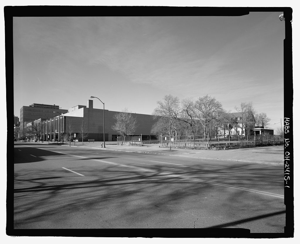
The significance of the support buildings was their contribution to the operation of the AWT and The AWT was the only facility capable of testing full-scale engines in simulated flight conditions. It contributed greatly to the development of the early turbojet engines. The SPC was one of the first large vacuum chambers in the nation. It was used extensively for the successful Project Mercury and Centaur rocket programs. In addition, the refrigeration system was the largest in the world when it came online in the It was capable of cooling millions of cubic feet of air in the AWT to minus forty-seven degrees Fahrenheit. It continues to refrigerate the IRT. 2.0 Architectural Information 2.1 Shop and Office Building The Shop and Office Building 7, (Fig.
6)) is a T-shaped building that served as the facility s center. It housed the tunnel s test section, control room, instrumentation, shop, and offices. The building is wide, 12 the height of central portion of the building was originally and the wings are long. This center section is much wider and taller than either of the wings. 13 The east wing contains two floors of offices and the west wing consists of a large two-story shop room. The three-story central portion of the building has two distinct areas. The northern front area, referred to as the high bay, is constructed in the same style as the two wings. This section now contains the Near-Field Antenna Test Facility. The southern, rear portion, referred to as the test chamber, was constructed separately.
It contained the AWT viewing platform on the third floor, the test section between the second and third floors, and the balance chamber below the test section. (Figs. 7 and 8 show plans for the three floors of the Shop and Office Building, and Fig. 9 shows a close-up aerial photograph.) In the early a control room for SPC No. 1 was constructed in the balance chamber. In the the area was reconfigured for the Far-Field Antenna Test Facility. SUPPORT BUILDINGS HAER No. OH-134 Page 5 Building Exterior The Shop and Office Building was constructed with blonde face brick matching the other buildings erected at the AERL.
Between and along the tops and the bottoms of the windows, the bricks were rusticated (staggered so that some bricks protruded further than others, creating a pattern on the flat brick wall, (Fig. The roof was edged with a limestone coping. 14 The original banded window scheme was identical for both the east and west wings. There were four identical 5'-7.75"-high twelve-pane horizontal sash windows running the length of the first and second floors. The second floor also contained a narrower eight-pane window near the center section. Below these on the east and west wing first floors were sets of metal and glass entrance doors. Two concrete steps led to the doors, and concrete canopies were overhead. The rows of windows in the wings had a continuous limestone sill along the bottom.
15 The building received a major rehabilitation in that included new windows, entrances, and other modifications. The west-facing side of the building had a window design similar to that on the north side (Fig. There were identical wide windows to the north and south of both floors with a narrower window in the center of the second floor. A metal and glass pedestrian entrance under a canopy was in the center on the first floor.16 The building s eastern side was identical to the western except that instead of a doorway there was a narrow window identical to that on the second floor. 17 The high bay had three sets of twelve windows vertically aligned on the upper levels of the north, east, and west walls. Each set was banded at the top, middle, and bottom with limestone coping.
18 A large truck entrance with a steel rolling door occupied the center area on the front (north) side providing direct access to the high bay, which ran from the front to the rear of the building (Fig. 19 The front of the high bay was expanded in the early The truck door was relocated to the west wall of the shop area, and the front facade was enclosed in The original front pedestrian doorways were immediately to the east and west of the truck door. There was another pedestrian entrance centered in the western wall of the shop area. Figures 13 and 14 are elevation drawings of the Shop and Office Building. Chamber Exterior The test chamber was in the rear of the high bay and had a design unique from the rest of the Shop and Office Building. The exterior walls were covered with transite.
There were five bands of the material running horizontally around the building. A narrower band ran along the uppermost portion. Later, when the rear overhang was lowered, two additional bands of sheeting were added. Two parallel corrugated metal coverings ran vertically down the south side of the building to shield pipes. The 20'-0"-diameter throat section of the wind tunnel penetrated the west wall of the test chamber on the second floor and exited the east wall (Fig. There were three twelve-pane square windows along top of the south wall and three longer thirty-six-pane windows along the top of the east and west walls. In the rear of the building, the second floor of the test chamber portion of the building overhung the first and was braced by steel supports (Fig.
Beneath the overhang were nozzles and plumbing for a large carbon-dioxide tank resting on the ground. At some point, the overhang was lowered. This was presumably done for the addition of the SPC No. 1 control room in the early SUPPORT BUILDINGS HAER No. OH-134 Page 6 Metal braces jutted out from the bottom of the overhang on the east and west sides and were attached to the side of the tunnel. Figures 17 and 18 show a room on the south wall of the test chamber and an aerial view of Shop and Office Building. Office Wing The eastern wing is separated from the other areas of the Shop and Office Building. This office wing is long and deep.
The first floor originally contained two small offices and a restroom on south wall, one large and one small office on the north wall, and a long office that ran the entire length of the east wall. A north/south entrance vestibule entered just to the east of the wall separating the wing from the high bay. There was a slight extension off the rear of the building that included a stairwell and storage room in the eastern rear corner and a restroom and foreman s room in the western rear corner. 20 The second floor originally included four small by offices along the north side and a long office that ran the entire length of the east wall. The south side included a large by office and a small1 fan room. Directly to the south of that was an 8'-2"-wide dark room and a restroom.
Access was provided by a stairwell in the south center area and a 3'-9"-wide hallway that extended north into the center of the wing and east through the offices. 21 Figures 19 to 22 show interior views of the Shop and Office Building. During the SPC period, the first floor offices were combined and enlarged to form three offices along the south wall, three along the north wall, and one small one in the center of the east wall. 22 The second floor remained the same except for the long office along the east wall, which was divided in two. 23 This layout has remained unchanged since the early-1960s (Figs. 23 and In and the Office and Shop Building underwent a major renovation. The original multipaned sash windows were replaced with large single-paned windows with aluminum frames.
New communications systems were installed, walls were repainted, the roof was repaired, new vents were installed, new office doorways were put in, and chalkboards were removed from the offices. 24 47 Shop Area The shop area is an open two-story space that occupies the entire western wing of the Shop and Office Building and opens up into the center high-bay area. Originally, it was wide and deep. 48 This large area was originally kept relatively empty except for a few workbenches and temporary test stands. A small office was located off the southwest corner of the room with access provided via the high-bay area. The ceiling and walls are still unfinished, with pipes, trusses, and ducts exposed. A large ventilation duct ran along the south wall.
Rows of fluorescent light fixtures were hung from the ceiling. 49 There were double glass and metal doors on the north and west walls for pedestrian entrance. There were originally nine twelve-paned sash windows along the north wall and four along the west wall with another eight-paned window above the door. The shop area was used to build and disassemble engines prior to and after their test runs in the AWT. An overhead two-rail crane ran east and west and could transport items to and from the SUPPORT BUILDINGS HAER No. OH-134 Page 7 high bay (Fig. Besides moving items east and west, the crane could move north and south along its cross rail, allowing access to any area in the shop.
As part of a project that included modifications to the Engine Research Building (ERB) loading dock, the north face of the Office and Shop Building was expanded northward. The first floor of the Shop Area was expanded by The section closest to the high bay was extended an additional to make it even with the high bay. A new concrete apron was placed outside the doorway on the west wall. 50 The expansion resulted in two new offices, a large control room, and a smaller computer room along the north wall. There was a low roof on the exterior of the offices. A stand-alone office was built inside the shop area near the high bay (Fig. 51 In June a canisterlike trailer designed for the Mercury Evaporating Condensing Analysis experiment was installed in the southwest corner of the shop (Fig.
Double doors provided access to one end, and four viewing portals ran lengthwise along each side of the trailer. The rear of the trailer had a large exhaust pipe. Inside, a work table was set up with a mercury collector at one end connected by a narrow condensation tube to a boiler. The trailer was removed after the tests, and by an exhauster hood had been installed in the same area. 52 In the mid-1970s, the shop was used as a garage and work area for NASA Lewis s electric automobile research (Fig. Every model electric vehicle available was tested. High Bay The three-story, 42'-0"-wide by 52'-7.25"-long high-bay area (Figs. 29 and 30) was used to transport test articles between the shop area in the western wing of the building and the test section in the rear.
53 Test articles were transported back and forth via an overhead ten-ton Shaw- Box crane that ran the length of the high bay (Fig. The crane continued rearward into the open test chamber area on the second floor. Originally there were no walls between the high bay and the shop or the upper level of the test chamber. A brick wall separated the high bay from the office wing. There was a window in the wall that provided a view of the truck door, high bay, and shop from the northwest second floor office. 54 The large open spaces in the high bay and shop areas were used to set up displays for various tours and inspections. The shop and high bay were converted into the MSL in the early (Figs. 32 to 34) as the proposed rehabilitation of the tunnel was being considered.
The MSL consisted of the Near-Field Antenna Test Facility and the Far-Field Antenna Test Facility. In the high bay was sealed off from the rear test section area. U-shaped, 36'-0"-high anechoic, radiofrequency-absorbing walls were built in the rear of the high bay. These walls, covered with row after row of foam pyramids to absorb any microwave rays that escaped the antenna, provided a precise test atmosphere that allowed researchers to scan a x area from just a few thousandths of an inch away from the surface. 55 The walls completely blocked the test section area to the south and partially blocked the shop area to the west. The brick wall to the east had always separated the room from the office wing.
There remains access to the high bay from the shop via a pedestrian door at the south corner and an open passageway at the north corner. 56 SUPPORT BUILDINGS HAER No. OH-134 Page 8 Originally there was a large truck door in the center of the north wall that was used to bring hardware, equipment, and test vehicles into the facility. In this truck entrance was sealed, and the 45.5'-0"-wide high bay was extended outward The first floor of the shop area also was extended at this time. A new concrete apron was placed outside the doorway on the west wall. 57 The exterior of the high-bay extension was covered with horizontal white metal panels that were framed by five vertical steel supports. 58 The addition of square feet of floor space enabled larger antenna systems to be tested (Fig.
This shop addition was used for a small radiofrequency laboratory, a near-field scanner control room, and an office. The new office and laboratory space facilitated the integration of the near-field and far-field antenna groups. The rehabilitation included associated structural, mechanical, and electrical modifications. 59 In there was a new effort to renovate the interior of area between the high bay and test section, and the hallway and first floor offices were modernized. Control Room and Other Areas There is a 23'-4"-long, 73'-10"-wide area between the high bay and the tunnel s test section. This three-level area is linked vertically by an elevator and flight of stairs.
The ground level of this area had an instrumentation room, an air lock into the tunnel s balance chamber, a restroom, and several other small rooms. Adjacent and to the east of this area was a by steam pit. The east end of this first floor area still connects to the eastern office wing of the building via both a stairwell to the second floor and a doorway leading to the building s first floor foyer. By the first floor rooms below the test section area had been remodeled and were being used for the Far-Field Antenna Test Facility. 60 There is an open stairway located between the high bay and the second floor test chamber. To the south of this stairway on the mezzanine level had been the x control room (Fig.
This was expanded in On the shop area side, the fan room and a x section of roof is opposite of where the control room is located. 61 Figure 37 shows a hallway in the rear of the Shop and Office Building. Basement The ground below the shop, high bay, and offices was largely unexcavated. There was a corridor that ran beneath the front pedestrian door to the back of the building. This corridor included a pedestrian tunnel that connected the AWT to the ERB (Figs. 38 and Adjacent to this was an area used for the Duct Lab wind tunnel. Underneath the test section are still two large storage rooms only accessible via a stairwell to the first floor. 62 Duct Lab A small supersonic wind tunnel called the Duct Lab was created in the AWT s basement corridor (Figs.
40 and It was used primarily for flow physics and supersonic injector studies. Originally constructed in to take advantage of excess AWT vacuum capabilities, the tunnel is still in working condition and was used through It can reach speeds of Mach 1.6 to 5.0 and temperatures of 400 degrees Fahrenheit. 63 The original control room was replaced by a new control room in 64 That control room was renovated in as part of the expansion of Building 7. 65 SUPPORT BUILDINGS HAER No. OH-134 Page 9 The 8'-0"-long, 4"-wide, 10"-high test section includes a hinged window for observation and to operate Schlieren apparatus. The removable Plexiglas or steel windows include rows of pressure taps. 66 The Duct Lab was supplied with air from the AWT s makeup air system.
The heated airflow entered a plenum chamber just upstream from the test section and was accelerated through a removable 50"-long nozzle. 67 After passing the text article, the air flowed through a 30"-long supersonic exhaust section with flexible walls 68 and was then decelerated by an 11'-7"-long variable-angle diffuser with a maximum diameter of 69 The airflow was then drawn through a 42"-diameter duct that exited through the floor and back to the Exhauster Building. 2.2 Exhauster Building The Exhauster Building 8 served as the Visitor Center until is currently the NASA Glenn Briefing Center) is a rectangular structure that was to the east of the AWT (Figs.
42 to This building performed two crucial roles for the wind tunnel it housed the drive motor that ran the tunnel s fan, and it contained the compressors that evacuated the tunnel to simulate the pressures at high altitudes. The 91'-8.5"-wide, 148'-0"-long Exhauster Building consisted of three sections. The main portion of the building was a two-story open room that housed the exhausters. The area to the south of this was divided into several rooms that housed large generators. A three-story, 13- square-foot-8.5-square-inch tower off the southwest corner of the building had housed the drive motor for the wind tunnel. The Exhauster Building was constructed by the Sam W. Emerson Company. Roots-Connersville supervised the installation of the exhausters, the Arthur E.
Magher Company assembled the exhausters after their delivery from Worthington during the summer of and GE installed the drive motor. 70 Construction began in the summer of and was completed by September 71 Exhausters The main room, which housed the exhausters, was tall. A large wooden platform supported by trusses had originally spanned the rear of the room. The room housed four four- cylinder, 60"-bore, 30"-stroke Worthington reciprocating exhausters (Fig. 46) that were powered by a 1750-horsepower motor. These exhausters were tied to the air scoop inside the wind tunnel. After removing the air from the tunnel, the pumps would expel it into the atmosphere through ducts in the Exhauster Building walls. Each exhauster had two horizontal 36"-diameter exhaust pipes.
The portal for each pipe was elevated from the ground and had a reinforced concrete collar and metal ring. An adjustable pipe roll stand was anchored just below the pipe to the wall. 72 Mufflers, perpendicular to the pipe and with concrete caps, were added to all eight of these pipes in 73 A smaller rectangular addition was attached to the northeast corner of the building in This new addition contained three eight-cylinder Ingersoll-Rand reciprocating pumps. 74 The AWT exhausters were initially constructed to handle seven pounds per second at and fifty-one pounds per second at With the new addition, the exhausters were upgraded to twelve SUPPORT BUILDINGS HAER No.
OH-134 Page 10 pounds per second at and sixty-six pounds per second at 75 An exhaust gas cooler, pump house, and cooler pit were also installed underneath the air scoop where the tunnel exited the east side of Building 7. 76 86 The addition was wide, long, and approximately high. The new compressors (Fig. 47) were positioned north and south and were joined together by a diameter pipe. The new compressors were linked to the new pump house via a 36"-diameter pipe that traveled through the original Exhauster Building. 87 The exterior was finished with a brick scheme identical to that on the original building.
There was a vertical lift door on the east end of the north side, a pedestrian doorway on the west end of the north side, and another pedestrian entrance on the west end of the south side. 88 Figures 48 and 49 show the addition. The air distribution system was modified again in A new 8'-0"-diameter, 228'-0"-long pipe was installed between the ERB and the AWT exhaust system. 89 In the Exhauster Building was renovated. The flooring was improved, obsolete hardware was removed from the walls, and a new sound-absorbing ceiling was installed. 90 Generators The rear portion of the Exhauster Building is tall and had consisted of two sections a narrow open area for the two power generators (Fig. 50) and a two-level area for offices.
The restrooms and a stairwell accessing the second floor were along the east wall behind the smaller generator. The second floor contained four small offices. 91 This area was used as the Solar Power Laboratory in the after the generators were no longer needed to operate the wind tunnel fan. The laboratory s work included the rapid assembling of the components of a large Brayton Cycle Power System so that they could be tested in the Space Power Facility 92 This room is presently used to store NASA educational publications. Drive Motor The southwest corner of the Exhauster Building was built like a three-story tower (Fig. The first level housed a small generator that helped power the AWT s drive motor. The drive motor occupied the upper two levels.
The drive shaft traveled from the upper level and into the tunnel shell on the east end of the facility. The tower rooms are wide and deep. These were accessible via an iron ladder in the northeast corner of the rooms. 93 The second level of the tower is above the first floor. The third level is another further. The second floor area had contained a secondary motor and fan that exhausted through a metal duct in the west wall. 94 The primary drive motor was an 1800-horsepower, 4000-volt, 2180-ampere GE induction motor (Fig. It sat on steel plates on the 6"-thick concrete base in the third level. There is another concrete slab along the north wall, but the remainder of the room s flooring consists of steel grating. The room has 3'-9.5"-wide windows on the north, south, and east walls.
95 The motor was wide at its base. The circular drive motor extended below the floor level and was supported by a concrete partition. The drive shaft (Fig. 53) rested on bases on either side of the motor. 96 The drive shaft traveled approximately between the exterior wall and the wind SUPPORT BUILDINGS HAER No. OH-134 Page 11 tunnel wall. 97 The drive shaft was elevated approximately from the ground. 98 Figure 54 is a diagram of the motor drive room. Visitor Center In the mid-1960s, the large exhausters were removed from the Exhauster Building, and the building was converted into the Solar Power Laboratory. In July the structure opened as the Aerospace Information Display (AID) building (Fig.
The AID contained NASA models, hardware, and exhibits, including large-scale models of an Apollo capsule, the Lunar Module, and all of NASA s launch vehicles. In the AID was expanded and renamed the Visitor Information Center (later shortened to the Visitor Center). A large lobby area was created at the nexus of the original Exhauster Building and the annex. The large exhauster room was filled with displays, an electronics shop, and restrooms, 99 and the annex became a 170-seat assembly room with a stage along the east wall. It also included an office and coat room. The second level, which does not cover the building s entire footprint, is now used as offices for the Community and Media Relations Office and the Educational Programs Office.
Its basement is used as storage for audiovisuals and educational displays. 100 The building served as the Visitor Center until Today it is the Briefing Center. 2.3 Refrigeration Building Overview The refrigeration system designed by the Carrier Corporation was one of the AWT s most vital and complex components. It could reduce the tunnel s temperature to minus forty-seven degrees Fahrenheit. In addition, it cooled the AWT s makeup air and fuel supply, as well as the IRT and the center s domestic chilled water (a centralized system for air conditioning buildings and laboratories). According to a Aero Digest article, if used for ice-making, (the system) would manufacture ten thousand tons of ice each twenty-four hours. 101 The Refrigeration Building (Figs.
56 to 59) contains the fourteen Carrier compressors and flash cooler that powered the cooling system. This rectangular, two-story brick structure was constructed in the same fashion as the Shop and Office Building. The building has a truck entrance in the center of the north face and pedestrian entrances on the south and east walls. An additional pedestrian entrance was installed on the north wall. Originally, the building contained two rows of sash windows along each wall. The second-level windows were later bricked over, and the lower-level windows were modernized. The interior of the building is largely open with an excavated basement. There is a small control room along the western wall.
The compressors are aligned in pairs facing east and west with the flash cooler running north and south between them. Several generators facing north are aligned near the rear of the building. There are two stairways leading to the basement, one near the control room, and the other near the front of the building. Cooling System The Carrier Corporation, based in Buffalo, New York, designed and constructed the refrigeration system. Originally, the NACA engineers wanted to use a new, untried cooling coil with SUPPORT BUILDINGS HAER No. OH-134 Page 12 streamlined tubes. Willis Carrier convinced the agency that his coils were superior, and the task was turned over to his company.
102 A scale model of the tunnel was built in at the Carrier plant so that their engineers could find a way to optimize the distribution of the refrigeration.103 The Pittsburgh-Des Moines Steel Company installed the refrigeration system, which included external coils and headers, liquid and vapor lines, expansion joints, and an exhauster trench. 104 Installation of the flash cooler began in mid-June and the entire building was completed in the fall of 105 Between the Refrigeration Building and the tunnel, approximately thirty different lines from the heat exchangers condensed into the four return pipes. The fourteen 1500-horsepower Carrier centrifugal compressors and the flash cooler (Fig. 60) were modified to use Freon-12 refrigerant.
Originally, the compressors changed the temperature of the Freon-12 by which equals 150 degrees Fahrenheit. A four-stage compressor took in a volume of gas, then released the superheated and compressed gas into the condenser. The condenser took water from the cooling tower to cool its tubes while the superheated gas from the compressor was passed around the four tubes. 106 The circulating water removed the heat from the refrigeration equipment to the cooling tower where it was dissipated into the atmosphere. At its original capacity, gallons of cooling water were required every minute. 107 Figure 61 shows some of the lines from the Refrigeration Building. The two-stage cooler subcooled the condensed refrigerant as it passed from the condenser to the cooler.
This process reduced the pressure and temperature to the pressure of the third-stage suction pressure, and the remaining refrigerant was evaporated. The horsepower-per-ton of refrigeration was substantially economized. The refrigerant was then pushed to the flash cooler where the suction gas was separated and the refrigerant was injected with hot gas. The refrigerant was subcooled in the flash cooler before the liquor pumps propelled it through the evaporator. The tunnel s heat also was absorbed by the latent heat contained in the excess refrigerant. 108 The dampers, which were regulated by thermostats, controlled the refrigeration system s weight flow and thus its power. Heat exchangers in the tunnel s western leg were used to create the low temperatures found at higher altitudes.
The AWT and IRT were cooled using almost identical heat exchangers. In an effort to maintain uniform temperature and frosting across the tunnel, engineers used eight identical heat exchangers that were four tubes deep. 109 The heat exchangers were a collection of 260 copper-plated coils arranged in a zigzag design that covered almost the entire cross section of the tunnel (Fig. A traditional cooling coil configuration, if used to cool such a large volume of air, would not have fit into the tunnel. The zigzag layout, however, created an area of airflow through the coils approximately four times the area of the tunnel cross section. 110 During the cooling cycle, a series of valves distributed the refrigeration uniformly across the tunnel.
Frost was created, and friction was caused by the coils. The heat exchanger vacuum was sustained during the defrosting cycle by valves located in two external float tanks. Two liquor pumps circulated the refrigerant from the flash cooler (Fig. 63) to the heat exchanger. The refrigerant gas was converted into liquor by compressors. 111 A purge recovery system evacuated any noncondensable gases, water, and air from the refrigeration system and gathered refrigerant mixed with the air. This resulted in ultimate efficiency and a clean refrigeration system. 112 SUPPORT BUILDINGS HAER No. OH-134 Page 13 Three 1500-horsepower York compressors were used to chill the cooling coils in the Air Dryer Building.
These compressors continue to supply domestic chilled water for air conditioning several nearby buildings including the ERB and the Administration Building. A natural gas compressor was installed for research in the Engine Components Research Laboratory. Five horizontal pumps and ten vertiline pumps distribute water from Cooling Tower No. 1 to Buildings 5, 8, 9, 11, 77, and 98. 113 The Refrigeration Building (Fig. 64) continues to provide cooling for the IRT. 2.4 Circulating Water Pump House As part of the modernization project for the AWT, a pump house was built underneath the northeast leg of the tunnel (Figs. 65 and The 54'-7.5"-long, 28'-1.5"-wide building ran in a diagonal southwest direction from the northeast portion of the tunnel near the exhaust scoop.
The pump house contained four Ingersoll-Rand pumps, two 250-horsepower discharge pumps to the south, and two 300-horsepower spray pumps. Another seventy-five-horsepower spray pump was located in the northeast corner. 114 These pumps drew water from Cooling Tower No. 1 through two and one 16"-diameter underground lines that ran from the cooling tower and through the Refrigeration Building (Fig. 115 A large cylindrical cooler pit was installed underneath the exhaust scoop in the northeast leg of the tunnel. This cooler was connected to the new pump house (Fig. The tunnel s air scoop funneled the contaminated air out the bottom of the tunnel and through this 10'-0"-long cooler.116 A 72"-diameter exhaust pipe extended from the back of the cooler (Fig.
It traveled vertically approximately including an expansion joint, before splitting. One pipe turned horizontally through the Exhauster Building and into the new addition. 117 The other ran north across Ames Road and connected with the ERB s exhaust system. 118 Figure 70 shows the cooler pit. During the this structure was renamed the Solar Power Laboratory Annex and used by the Technical Services Division s Refrigeration Section for storage and as a shop and tool crib area (Figs. 71 to The Solar Power Laboratory was located nearby in the southwest corner of the Exhauster Building. 119 In recent years, the pump house building had been used for storage by the Educational Services Division. The structure was demolished in as part of the AWT demolition. 2.5 Cooling Tower No.
1 Cooling Tower No. 1 sits behind the Refrigeration Building diagonally in a northwest direction along Moffett Road. It is a narrow rectangular structure with a square settling basin off the northeast side. Cooling Tower No. 1 originally had eight pairs of fans in its roof to draw the air upwards to remove heat from the higher temperature water that was delivered high in the cooling tower and cascaded water spray down into the 600,000-gallon basin at the bottom of the tower. In the mid-1950s, it could pump gallons per minute. 120 Currently, five underground lines run northward from the tower before forming right angles toward the IRT. Two lines, ranging from 6" to 18" in diameter, exit each of the larger lines and enter the north wall of the Refrigeration Building.
These lines had exited the Refrigeration Building and connected to the Circulating Water Pump House through two 24"-diameter lines SUPPORT BUILDINGS HAER No. OH-134 Page 14 and one 16"-diameter line. 121 Two other lines, 24" and 30" in diameter, currently exit the south side of the cooling tower and wrap around and connect to the ERB. 122 In an additional cell was added to each end of the tower resulting in four new fans. There is an auxiliary water basin in the center off the north side, and a large tank area to the west of this basin contains three tanks (Fig. Over several years, all of the cells were rehabilitated, and in the mid1980s, the facility was largely rebuilt. 123 It is still used by the IRT in conjunction with the Refrigeration Building (Figs.
75 and 2.6 Air Dryer Building The makeup air system was designed to replenish the air in the AWT that was removed by the exhaust scoop. The Air Dryer Building, located externally outside the tunnel s southwest corner, removed condensation and cooled the air to prevent shocks to the airflow as it entered the tunnel. The facility consisted of the air dryer tank and two sets of cooling coils (Fig. The approximately 28'-8"-diameter tank was enclosed in a two-story brick building with cooling coils located before and after. It was connected in front and behind by large ducts to the Primary Coils Building and the Secondary Coils Building. The Primary Coils Building was wide and long. The Secondary Coils Building was wide and long.
124 Ambient air entered the Primary Coils Building from the south and passed through a damper, a bank of filters, the two cooling coils, an eliminator, and another damper, which reduced its temperature to about forty degrees Fahrenheit. 125 The air then entered the air dryer tank where four flat beds of activated alumina layered on top of one another absorbed moisture to a dew point of minus seventy degrees Fahrenheit. 126 The air then entered the Secondary Coils Building north of the dryer; this cooled the air to the desired tunnel temperature of approximately minus seventy degrees Fahrenheit. The dryer s cooling coils were cooled by twelve reciprocating York compressors located in the nearby Refrigeration Building.
A large duct permitted airflow between the air dryer and the primary coils during cooling and activation. 127 The alumina had to be reactivated between runs by running steam-heated air through the dryer in the reverse direction. It required approximately five hours to remove all the moisture from the alumina. The beds were then cooled by running chilled air through the dryer. 128 The resulting cool, dry air was pumped to both the AWT and the adjacent Small Supersonic Wind Tunnels Building through a 48"-diameter pipe. The conditioned air was introduced into the AWT through pressure-sensitive valves in two portals in the western tunnel wall.
The southern 48" portal allowed some of the air in, but a portion was redirected through a pipe that narrowed from 60" to 36" in diameter and was tied into the Refrigeration Building. 129 This uncontaminated air was then pumped from the refrigeration system into the tunnel upstream from the test section. 130 During a upgrade, a new air tank was built on top of the existing tank and new cooling coils were installed on top of the existing Primary Coils Building, replacing the function of the original equipment (Fig. 78 to The original duct was redirected to this upper chamber and a U-shaped reactivation duct connected the north side of this new chamber to the Primary Coils Building.
131 Based on aerial photographs, it appears that the makeup air line directed to the Refrigeration Building was removed in August 132 The air dryer tank was demolished SUPPORT BUILDINGS HAER No. OH-134 Page 15 sometime prior to The Primary Coils Building 18 1) became the Fire Pump Building. The Secondary Coils Building 18 2) became the Gas Compressor Building. Figure 81 shows the Air Dryer Building as it looked in 2.7 Small Supersonic Tunnels Building In the summer of the laboratory s first supersonic wind tunnel was built between the AWT and the IRT. Two other supersonic tunnels were added vertically to this structure in and The tunnels were housed in an L-shaped building directly behind the southwest corner of the AWT.
The Small Supersonic Tunnels Building was informally known as the Stack Tunnels because its three tunnels were aligned vertically (Fig. Because of the arrangement made with the local electric company, the AWT only ran during the night, so its exhausters sat idle most of the day. Abe Silverstein, who was Chief of the Engine Installation Division at the time, decided to use the AWT exhausters to create a small supersonic tunnel. He designed the 2.25-square-foot open-circuit tunnel. GE was hired in May to provide the drive motors and auxiliary equipment. The first tunnel was built in just ninety days. 133 The airflow for the tunnels was supplied by the AWT makeup air line. The line originated in the Air Dryer Building and was split at the southwest corner of the AWT (Fig.
One end fed conditioned air into the AWT, and the other end traveled east where it was ducted into one of the Small Supersonic Wind Tunnels. After passing through one of the test sections, the 48"-diameter exhaust line exited to the east then split (Fig. One section tied directly into the AWT s south wall and the other ran to the AWT s exhaust cooler. 134 The control room was in the basement of the building with a large collection of manometer boards. Half a story above the basement was Tunnel No. 1, which had an 18" x 18" test section and could reach Mach Tunnel No. 2 was a Mach tunnel that was long and had a 24" x 24" test section, and Tunnel No. 3 was a Mach tunnel that was long and had a 18" x 18" test section. 135 Early tests in Tunnel No.
1 focused on supersonic diffusers, supersonic ramjets (Fig. and supersonic aerodynamics. 136 In and tests included inlet studies for North American (aircraft manufacturer) and light gas injection wing burning and high-altitude rocket ignition for NASA. Tunnel No. 2 was activated in September and included hydrogen peroxide fuel and gaseous nitrogen systems. Tunnel No. 3 came online in July The latter two tunnels were used for North American inlet tests, NASA noise studies, and drogue parachute configurations in and 137 NASA Lewis became more and more involved with space, and despite modest annual operating costs of for Tunnel No. 1 and each for Tunnels No. 2 and No. 3, the facility had been deactivated by 138 Figure 86 shows where the Small Supersonic Wind Tunnels had tied into the AWT.
The building was finally demolished sometime between and SUPPORT BUILDINGS HAER No. OH-134 Page 16 3.0 Index of Support Building Photographs Many C-numbered photographs are available from NASA s or NASA Glenn s image archives: NASA Image eXchange (NIX, http://nix.nasa.gov/) GRC ImageNet Page Figure 1. AWT complex including the Exhauster Building 8, left), the Shop and Office Building 7, center), and the Refrigeration Building 9, right), 27 Figure 2. Location map for the AWT support buildings, (OH_Cuyahoga_AWT- 28 Figure 3. AWT with its internal components and support buildings, 29 Figure 4. Shop and Office Building, 30 Figure 5. Demolition plan for the AWT. Areas that were demolished are indicated by hash marks, 31 Figure 6.
Shop and Office Building, with the shop area in the foreground (viewed from the northwest), 32 Figure 7 Plan of the first floor of the Shop and Office Building, 33 Figure 8 Plan of the second and third floors of the Shop and Office Building, 33 Figure 9. Design differences in the test chamber and high bay of the Shop and Office Building (viewed from the south), 34 Figure 10. Original sash windows and rustication pattern in the brick on the exterior of the Shop and Office Building, 34 Figure 11. Original west-facing exterior of the Shop and Office Building. The eastern end was similar without the doorway, 35 Figure 12. Original high bay exterior with truck and pedestrian entrances (viewed from the northwest), 35 Figure 13. Elevation drawing of Shop and Office Building, 36 Figure 14.
Elevation drawing of Shop and Office Building, 37 Figure 15. Exterior of the test chamber in the Shop and Office Building (viewed from the west), 38 Figure 16. Test chamber overhang in the rear of the Shop and Office Building (viewed from the east), 39 Figure 17. Inside a room on the south wall of the test chamber next to the tunnel test section (viewed from the west), 39 Figure 18. Exterior of the Shop and Office Building s office wing (viewed from the northwest), 40 Figure 19. First floor hallway in the office wing of the Shop and Office Building (viewed from the west), (C NASA Glenn). 40 SUPPORT BUILDINGS HAER No. OH-134 Page 17 Figure 20. Original entrance vestibule in the office wing of the Shop and Office Building (viewed from the south), 41 Figure 21.
Interior of an office with original windows in the office wing of the Shop and Office Building, 41 Figure 22. New windows and light fixtures after the renovation of the Shop and Office Building, 42 Figure 23. Shop and Office Building during the drawing updated 43 Figure 24. Shop and Office Building during the drawing updated 44 Figure 25. Shop area in the AWT Shop and Office Building showing the overhead crane (viewed from the northeast), 45 Figure 26. Original first floor shop office with the main shop area visible through the window and doorway, 46 Figure 27. Mercury Evaporating Condensing Analysis experiment installed in the southwest corner of the shop area, 47 Figure 28. Electric vehicle research in the shop area during the mid-1970s, 47 Figure 29.
Interior of the high bay where it connects with the shop area in the Shop and Office Building, 48 Figure 30. High bay showing a window to the office wing and elevator; stairs to the test chamber are to the right (viewed from the west), (OH_Cuyahoga_AWT- 49 Figure 31. Overhead ten-ton crane that ran from the high bay into the test chamber, 49 Figure 32. Near-Field Antenna Test Facility installed in the high-bay area of the Shop and Office Building, 50 Figure 33. Building 7 after its conversion to the Microwave Systems Laboratory and the expansion of the shop, 51 Figure 34. Wall built between the high bay and the test chamber for the Near-Field Antenna Test Facility, 52 Figure 35. The extension of the high bay and shop area (viewed from the north), 52 Figure 36.
Original AWT control room inside the Shop and Office Building, 53 Figure 37. Hallway at the rear of the office wing and stairs leading to the basement and the second floor of offices, 54 Figure 38. Basement floor plan showing excavated areas and the Duct Lab tunnel, 55 Figure 39. Basement corridor with the Duct Lab beneath the Shop and Office Building, 55 Figure 40. Duct Lab, a 4" x 10" wind tunnel, in the basement corridor beneath the Shop and Office Building, 56 Figure 41. Elevation drawing of the Duct Lab supersonic wind tunnel, 56 SUPPORT BUILDINGS HAER No. OH-134 Page 18 Figure 42. Isometric drawing of original layout of AWT Exhauster Building, 57 Figure 43. Elevation drawing of the Exhauster Building, (OH_Cuyahoga_AWT- 58 Figure 44.
Elevation drawing of the Exhauster Building, (OH_Cuyahoga_AWT- 59 Figure 45. Elevation drawing of the Exhauster Building, (OH_Cuyahoga_AWT- 60 Figure 46. One of four Worthington exhausters with its two 36"-diameter exhaust pipes in the Exhauster Building, 61 Figure 47. Ingersoll-Rand exhausters in the addition to the Exhauster Building, 61 Figure 48. Former Exhauster Building, with the addition off the northeast corner (viewed from the north), 62 Figure 49. Two exhausters added to the Exhauster Building, 63 Figure 50. One of two generators in the Exhauster Building that were used to help power the AWT drive motor, 64 Figure 51. Drive motor tower in rear of the Exhauster Building (viewed from the south) 65 Figure 52.
General Electric induction motor that was used to drive the AWT fan (viewed from the northeast), 66 Figure 53. Drive shaft that formerly exited this western wall of the Exhauster Building to rotate the AWT fan, 66 Figure 54. Motor drive room in Exhauster Building, (OH_Cuyahoga_AWT- 67 Figure 55. AID in the former Exhauster Building, (OH_Cuyahoga_AWT- 68 Figure 56. Isometric drawing of the Refrigeration Building, which housed the cooling system for the AWT and the Icing Research Tunnel, (OH_Cuyahoga_AWT- 69 Figure 57. Elevation drawing of the Refrigeration Building, 70 Figure 58. Sections and cross sections of the Refrigeration Building, 71 Figure 59. Sections of the Refrigeration Building, (OH_Cuyahoga_AWT- 72 Figure 60.
Flash cooler being prepared for installation in the Refrigeration Building in July 73 Figure 61. Lines from the Refrigeration Building entering the west wall of the AWT (viewed from the northwest), 74 Figure 62. Accordion-shaped banks of cooling coils inside the AWT, 75 Figure 63. Flash cooler and Carrier compressors inside the Refrigeration Building (viewed from the south), 75 SUPPORT BUILDINGS HAER No. OH-134 Page 19 Figure 64. Refrigeration Building, with the AWT to the left in the background (viewed from the north), 76 Figure 65. Piping and sumps for the Circulating Water Pump House, 77 Figure 66. Former Circulating Water Pump House beneath the AWT (viewed from the west), 78 Figure 67.
Three of four sump pumps inside the Circulating Water Pump House during its construction in 78 Figure 68. Installation of the exhaust gas cooler under the northeast tunnel section during the upgrade of the AWT, 79 Figure 69. 72"-diameter pipe connecting the cooler pit to the Exhauster Building and the ERB, 80 Figure 70. Cooler pit area under the northeast portion of the tunnel (viewed from the west), 81 Figure 71. Former Circulating Water Pump House (viewed from the west), 81 Figure 72. Cleaning section for the solar power mirrors in the old pump house, 82 Figure 73. Elevation drawing for the Circulating Water Pump House, 83 Figure 74. Cooling Tower No. 1 plan, revised (OH_Cuyahoga_AWT- 84 Figure 75. Cooling Tower No. 1 (viewed from the southwest), 85 Figure 76. Cooling Tower No.
1 with its settling basins in the foreground (viewed from the northwest), 85 Figure 77. Original air dryer setup with the secondary coils (left), dryer tank (center), and primary coils (right) (viewed from the west), (OH_Cuyahoga_AWT- 86 Figure 78. Air Dryer Building after a new dryer tank and primary coils were added on top (viewed from the northwest), 87 Figure 79. Plan and elevation drawing for the Air Dryer Building addition, 88 Figure 80. Elevation drawings of the Air Dryer Building, 89 Figure 81. Air Dryer Building showing air pipes feeding the AWT (left) and the Small Supersonic Tunnels (right) (viewed from the southwest), 90 Figure 82. Isometric drawing of the Small Supersonic Wind Tunnels Building as envisioned in 91 Figure 83.
Line from the air dryer feeding the Small Supersonic Wind Tunnels (viewed from the southwest), 91 Figure 84. Small Supersonic Wind Tunnels exhaust tie-in with the AWT (viewed from the east), 92 Figure 85. Ramjet model in Tunnel No. 2, the 24" x 24" Small Supersonic Wind Tunnel, 92 SUPPORT BUILDINGS HAER No. OH-134 Page 20 Figure 86. Portals in the south leg of the AWT where the Small Supersonic Wind Tunnels formerly tied in, 93 SUPPORT BUILDINGS HAER No. OH-134 Page 21 4.0 References 1 Finished Grading Plan for Area Bounded by Roads B, C, & D, in NASA Glenn Central Drawing Files (Cleveland, Ohio: NACA AERL, drawing ED 1. 2 Sharon Maier, Engine Research Building (ERB): Flow Physics Facilities Duct Lab, 4- by 10-in.
Supersonic Wind Tunnel (Cleveland, Ohio: NASA Glenn Research Center, January 24, 3 AERL Construction Report No. 66, (Cleveland, Ohio: NASA Glenn History Collection, Directors Collection, 4 Charles Herman, AERL Construction Report No. January 1, (Cleveland, Ohio: NASA Glenn History Collection, Directors Collection, box 3 of 5, 5 AERL Construction Report No. (Cleveland, Ohio: NASA Glenn History Collection, Directors Collection, 6 Charles Herman, AERL Construction Report No. August 28, (Cleveland, Ohio: NASA Glenn History Collection, Directors Collection, box 3 of 5, 7 AERL Construction Report No. November 8 13, (Cleveland, Ohio: NASA Glenn History Collection, Directors Collection, 8 AERL Construction Report No.
(Cleveland, Ohio: NASA Glenn History Collection, Directors Collection, 9 Harold Friedman, interview by Robert S. Arrighi, Beachwood, Ohio, November 2, (Cleveland, Ohio: NASA Glenn History Collection, Oral History Collection). 10 Walter Vincenti, interview by Glenn Bugos, Moffett Field, California, May (Cleveland, Ohio: NASA Glenn History Collection, Oral History Collection). 11 Virginia Parker Dawson, Engines and Innovation: Lewis Laboratory and American Propulsion Technology (Washington, DC: NASA SP App.
B, accessed June 4, 12 Engine Research Wind Tunnel Office and Shop Building Second Floor Plan (Cleveland, Ohio: NACA AERL, April drawing ED 206 (previously D 13 Engine Research Wind Tunnel Office and Shop Building Elevations (Cleveland, Ohio: NACA AERL, November drawing ED 208 (previously D 14 Engine Research Wind Tunnel, drawing ED 15 Engine Research Wind Tunnel, drawing ED 16 Engine Research Wind Tunnel, drawing ED 17 Engine Research Wind Tunnel Office and Shop Building Elevations Wall Deleted (Cleveland, Ohio: NACA AERL, November drawing ED 209 (was D 18 Engine Research Wind Tunnel, drawing ED 19 Engine Research Wind Tunnel Office and Shop Building First Floor Plan (Cleveland, Ohio: NACA AERL, October 30, ED 205 A drawing (was D 2050A). 20 Engine Research Wind Tunnel, drawing ED 205 A.
21 Engine Research Wind Tunnel, drawing ED 22 Space Power Chambers Office and Shop Building, First Floor Plan (Cleveland, Ohio: NASA Lewis Research Center, September drawing CD 23 Space Power Chambers Office and Shop Building, Second Floor Plan (Cleveland, Ohio: NASA Lewis Research Center, September drawing CD 24 SPC Shop and Office Building Modernization and Rehabilitation (Cleveland, Ohio: NASA Lewis Research Center, drawing CF SUPPORT BUILDINGS HAER No.
OH-134 Page 22 25 SPC Shop and Office Building Modernization and Rehabilitation (Cleveland, Ohio: NASA Lewis Research Center, drawing CF 26 SPC Shop and Office Building Modernization and Rehabilitation (Cleveland, Ohio: NASA Lewis Research Center, drawing CF 27 SPC Shop and Office Building Modernization and Rehabilitation (Cleveland, Ohio: NASA Lewis Research Center, drawing CF 28 SPC Shop and Office Building Modernization and Rehabilitation (Cleveland, Ohio: NASA Lewis Research Center, drawing CF 29 SPC Shop and Office Building Modernization and Rehabilitation (Cleveland, Ohio: NASA Lewis Research Center, drawing CF 30 SPC Shop and Office Building Modernization and Rehabilitation (Cleveland, Ohio: NASA Lewis Research Center, drawing CF 31 SPC Shop and Office Building Modernization and Rehabilitation (Cleveland, Ohio: NASA Lewis Research Center, drawing CF 32 SPC Shop and Office Building Modernization and Rehabilitation (Cleveland, Ohio: NASA Lewis Research Center, drawing CF 33 SPC Shop and Office Building Modernization and Rehabilitation (Cleveland, Ohio: NASA Lewis Research Center, drawing CF 34 SPC Shop and Office Building Modernization and Rehabilitation (Cleveland, Ohio: NASA Lewis Research Center, drawing CF 35 SPC Shop and Office Building Modernization and Rehabilitation (Cleveland, Ohio: NASA Lewis Research Center, drawing CF 36 SPC Shop and Office Building Modernization and Rehabilitation (Cleveland, Ohio: NASA Lewis Research Center, drawing CF 37 SPC Shop and Office Building Modernization and Rehabilitation (Cleveland, Ohio: NASA Lewis Research Center, drawing CF 38 SPC Shop and Office Building Modernization and Rehabilitation (Cleveland, Ohio: NASA Lewis Research Center, drawing CF 39 SPC Shop and Office Building Modernization and Rehabilitation (Cleveland, Ohio: NASA Lewis Research Center, drawing CF 40 SPC Shop and Office Building Modernization and Rehabilitation (Cleveland, Ohio: NASA Lewis Research Center, drawing CF 41 SPC Shop and Office Building Modernization and Rehabilitation (Cleveland, Ohio: NASA Lewis Research Center, drawing CF 42 SPC Shop and Office Building Modernization and Rehabilitation (Cleveland, Ohio: NASA Lewis Research Center, drawing CF 43 SPC Shop and Office Building Modernization and Rehabilitation (Cleveland, Ohio: NASA Lewis Research Center, drawing CF 44 SPC Shop and Office Building Modernization and Rehabilitation (Cleveland, Ohio: NASA Lewis Research Center, drawing CF 45 SPC Shop and Office Building Modernization and Rehabilitation (Cleveland, Ohio: NASA Lewis Research Center, drawing CF 46 SPC Shop and Office Building Modernization and Rehabilitation (Cleveland, Ohio: NASA Lewis Research Center, drawing CF 47 SPC Shop and Office Building Modernization and Rehabilitation (Cleveland, Ohio: NASA Lewis Research Center, drawing CF SUPPORT BUILDINGS HAER No.
OH-134 Page 23 48 Engine Research Wind Tunnel, drawing ED 49 Office in the Shop Area of Shop and Office Building (Cleveland, Ohio: NASA Lewis Research Center, photograph C 50 Addition to Building No.
7, Site Plan and Site Details (Cleveland, Ohio: NASA Lewis Research Center, March drawing CF 51 Microwave Systems Laboratory Building 7 First Floor Plan (Cleveland, Ohio: NASA Lewis Research Center, October drawing CF 52 Office in the Shop Area, photograph C 53 Engine Research Wind Tunnel, drawing ED 54 Martin Brown, Centaur Parts Coming Into NASA Lewis Research Center and Unloading (Cleveland, Ohio: NASA Lewis Research Center, photograph C accessed June 20, 55 New Test Facility Investigates Large Space Antennas, Lewis News, December 16, 56 Modifications to the Near Field Microwave Lab, Partial First Floor Plan, Framing, Elevations, Details (Cleveland, Ohio: NASA Lewis Research Center, July 11, drawing CF 57 Addition to Building No. 7, drawing CF 58 Addition to Building No.
7, Elevations and Building Section (Cleveland, Ohio: NASA Lewis Research Center, March drawing CF 59 Wind Tunnel, Loading Dock Are Upgraded, Lewis News, March 21, 60 Microwave Systems Laboratory, drawing CF 61 Engine Research Wind Tunnel, drawing ED 62 Microwave Systems Laboratory 7 Basement Floor Plan (Cleveland, Ohio: NASA Lewis Research Center, October drawing CF 63 Maier, Engine Research Building (ERB). 64 New Control Room for the Wind Tunnel, SPC Building 7 (Cleveland, Ohio: NASA Lewis Research Center, May drawing CF 65 Modifications to Duct Lab, SPC Basement, Plan, Sections, Details (Cleveland, Ohio: NASA Lewis Research Center, December 4, drawing CF 66 Maier, Engine Research Building (ERB).
67 Inch Supersonic Wind Tunnel in Duct Lab, General Assembly (Cleveland, Ohio: NACA AERL, November drawing EE 68 Inch Supersonic Wind Tunnel in Duct Lab, General Assembly (Test Section) (Cleveland, Ohio, NACA AERL, November drawing ED 69 Inch Supersonic Wind Tunnel in Duct Lab, Variable Angle Diffuser Assembly (Cleveland, Ohio: NACA AERL, November drawing ED 70 AERL Construction Report No. 71 Charles Herman, Construction Report No. September 4, (Cleveland, Ohio: Director s Records, box 3 of 5, 72 Exhauster Building Details of Exhaust Pipes Through the Wall (Cleveland, Ohio: NACA AERL, December drawing ED 73 Exhauster Building, Plan of Mufflers and Section A-A (Cleveland, Ohio: NACA AERL, May drawing ED 74 Altitude Wind Tunnel.
NACA Lewis Research Center, July 11, (Cleveland, Ohio: NASA Glenn History Collection, Directors Collection, SUPPORT BUILDINGS HAER No. OH-134 Page 24 75 John Esterly, Milton Beheim, and Arthur Gnecco, Survey of Altitude Test Facilities and Wind Tunnels, NASA Lewis, January 28, 82.
76 Modernization of Altitude Wind Tunnel (Cleveland, Ohio: NASA Glenn Research Center, image C 77 Modernization of Altitude Wind Tunnel (Cleveland, Ohio: NASA Glenn Research Center, image C 78 Modernization of Altitude Wind Tunnel (Cleveland, Ohio: NASA Glenn Research Center, image C 79 Modernization of Altitude Wind Tunnel (Cleveland, Ohio: NASA Glenn Research Center, image C 80 Modernization of Altitude Wind Tunnel (Cleveland, Ohio: NASA Glenn Research Center, image C 81 Modernization of Altitude Wind Tunnel (Cleveland, Ohio: NASA Glenn Research Center, image C 82 Modernization of Altitude Wind Tunnel (Cleveland, Ohio: NASA Glenn Research Center, image C 83 Modernization of Altitude Wind Tunnel (Cleveland, Ohio: NASA Glenn Research Center, image C 84 Modernization of Altitude Wind Tunnel (Cleveland, Ohio: NASA Glenn Research Center, image C 85 Modernization of Altitude Wind Tunnel (Cleveland, Ohio: NASA Glenn Research Center, image C 86 Modernization of Altitude Wind Tunnel (Cleveland, Ohio: NASA Glenn Research Center, image C 87 AWT Modernization, Exhauster Addition 1st Floor and Roof Plans (Cleveland, Ohio: NACA Lewis Flight Propulsion Laboratory, February drawing CD 88 AWT Modernization, Exhauster Building Elevations and Sections (Cleveland, Ohio: NACA Lewis Flight Propulsion Laboratory, February drawing CD 89 Modification of Air Distribution System, Plan and Sections Diam.
Pipe (Cleveland, Ohio: NACA Lewis Flight Propulsion Laboratory, August drawing CD 90 Modifications and Additions to Altitude Wind Tunnel Exhauster Building (Cleveland, Ohio: NASA Lewis Research Center, November drawing CD 91 Solar Power Laboratory Floor Plans (Cleveland, Ohio: NASA Lewis Research Center, revised reference drawing CE 92 Lewis Deadlines Met, Lewis News, February 14, 93 Engine Research Wind Tunnel Propeller Drive Motor Ventilating System (Cleveland, Ohio: NACA AERL, December drawing ED 94 Engine Research Wind Tunnel Propeller Drive Motor Ventilating System (Cleveland, Ohio: NACA AERL, August drawing ED 95 Engine Research Wind Tunnel, drawing ED 96 Engine Research Wind Tunnel, drawing ED 97 Engine Research Wind Tunnel, drawing ED 98 Exhauster Building Elevations (Cleveland, Ohio: NACA AERL, December drawing ED 99 Fire Protection Visitors Information Center Building 8, Plans and Isometric (Cleveland, Ohio: NASA Lewis Research Center, December 8, drawing CF SUPPORT BUILDINGS HAER No.
OH-134 Page 25 100 Buildings and Facilities. NASA Lewis Research Center, April (Cleveland, Ohio: NASA Glenn History Collection, Facilities Collection, 101 John Victory, New NACA Wind Tunnels, Aero Digest, August 1, 102 Margaret Ingels, Willis Haviland Carrier: Father of Air Conditioning. Carrier Corporation (Louisville, Kentucky: Fetter Printing Co., 97 103 Ingels, Willis Haviland Carrier, 97 104 AERL Construction Report No. 105 Memorandum C Naw from Contractor s Conference, May 29, (Washington, DC: Staff Memos, 106 Operation and Maintenance of Refrigeration Plant Installed at Altitude Wind Tunnel. (Cleveland, Ohio: Carrier Corporation, 15. 107 Ernest G.
Whitney, Lecture 22 Altitude Wind Tunnel at AERL (Cleveland, Ohio: NASA Glenn History Collection, Altitude Wind Tunnel Collection, June 23, 3. 108 Operation and Maintenance, 15. 109 Walter Olson, The Icing Research Tunnel Refrigeration Heat Exchanger: How the System Works (Cleveland, Ohio: NASA Lewis Research Center, May 110 Operation and Maintenance, 16. 111 Operation and Maintenance, 16 21. 112 Operation and Maintenance, 16. 113 Buildings and Facilities. 114 Exhauster Building Altitude Exhaust and CTW System.
Ingersoll Rand Exhausters Location Plan (Cleveland, Ohio: NACA Lewis Flight Propulsion Laboratory, February drawing CD 115 Fuel System Cooler Pit and Pump House Cooling Tower Water Pumps and Piping (Cleveland, Ohio: NACA Lewis Flight Propulsion Laboratory February drawing CE 116 Modification of Air Distribution System, Plan Elevations and Sections Air Scoop at Wind Tunnel (NACA Lewis Flight Propulsion Laboratory, October drawing CD 117 AWT Modernization, Process Piping & Exhaust Air System (Cleveland, Ohio: NASA Lewis Research Center, April drawing CE 118 Schematic Drawing of NACA Altitude Wind Tunnel (Cleveland, Ohio: NACA Lewis Flight Propulsion Laboratory, drawing C 119 Buildings and Facilities. 120 Altitude Wind Tunnel. July 11, 121 Altitude Wind Tunnel Area.
Cooling Tower Water Supply and Pumped Return Refrigerated Water Supply and Return (Cleveland, Ohio: NACA Lewis Flight Propulsion Laboratory, April image CD 122 Altitude Wind Tunnel Area, image CD 123 Facility Operations and Maintenance Division, Lewis News, January 9, 124 Air Dryer, Primary and Secondary Coils Building Plans (Cleveland, Ohio: NACA AERL, January drawing EE 125 Air Dryer No.1, Tank Reactivation Duct and Primary System (Cleveland, Ohio: NACA Lewis Flight Propulsion Laboratory, October drawing CD 126 Whitney, Lecture 22, 2. 127 AWT Facilities Addition Air Dryer Building Plan and Elevation (Cleveland, Ohio: NACA AERL, May drawing CD SUPPORT BUILDINGS HAER No. OH-134 Page 26 128 AWT Facilities, drawing CD 129 Whitney, Lecture 22, 2. 130 Victory, New NACA Wind Tunnels.
131 AWT Facilities, drawing CD 132 150 PSIG Combustion Air Lines Extension to AWT and IRT, Demolition Plan and Reaction (Cleveland, Ohio: NASA Lewis Research Center, August 28, drawing CF 133 NACA Announces New Supersonic Wind Tunnel for Jet Propulsion Research, Wing Tips, August 11, 134 Space Power Chambers & Icing Research Tunnel Process Systems (Cleveland, Ohio: NASA Lewis Research Center, November drawing CD 135 Major Research Facilities of the Lewis Flight Propulsion Laboratory, in Wind Tunnels Small Supersonic Wind Tunnels (Cleveland, Ohio: NACA Lewis, July 24, 1. 136 Carlton Kemper, letter to NACA regarding Outline of Research Projects for the 18 by 18 Inch and 20 Inch Supersonic Tunnels at the Cleveland Laboratory, October 4, 137 NASA DOD Wind Tunnel Survey. Budget Bureau No.
22 138 NASA DOD Wind Tunnel Survey. SUPPORT BUILDINGS HAER No. OH-134 Page 27 Appendix Figures and Images Figure 1. AWT complex including the Exhauster Building 8, left), the Shop and Office Building 7, center), and the Refrigeration Building 9, right), SUPPORT BUILDINGS HAER No. OH-134 Page 28 Figure 2. Location map for the AWT support buildings, SUPPORT BUILDINGS HAER No. OH-134 Page 29 Figure 3. AWT with its internal components and support buildings, SUPPORT BUILDINGS HAER No. OH-134 Page 30 Figure 4. Shop and Office Building, SUPPORT BUILDINGS HAER No. OH-134 Page 31 Figure 5. Demolition plan for the AWT. Areas that were demolished are indicated by hash marks, SUPPORT BUILDINGS HAER No. OH-134 Page 32 Figure 6.
Shop and Office Building, with the shop area in the foreground (viewed from the northwest), SUPPORT BUILDINGS HAER No. OH-134 Page 33 Figure 7 Plan of the first floor of the Shop and Office Building, Figure 8 Plan of the second and third floors of the Shop and Office Building, SUPPORT BUILDINGS HAER No. OH-134 Page 34 Figure 9. Design differences in the test chamber and high bay of the Shop and Office Building (viewed from the south), Figure 10. Original sash windows and rustication pattern in the brick on the exterior of the Shop and Office Building, SUPPORT BUILDINGS HAER No. OH-134 Page 35 Figure 11. Original west-facing exterior of the Shop and Office Building. The eastern end was similar without the doorway, Figure 12.
Original high bay exterior with truck and pedestrian entrances (viewed from the northwest), SUPPORT BUILDINGS HAER No. OH-134 Page 36 Figure 13. Elevation drawing of Shop and Office Building, SUPPORT BUILDINGS HAER No. OH-134 Page 37 Figure 14. Elevation drawing of Shop and Office Building, SUPPORT BUILDINGS HAER No. OH-134 Page 38 Figure 15. Exterior of the test chamber in the Shop and Office Building (viewed from the west), SUPPORT BUILDINGS HAER No. OH-134 Page 39 Figure 16. Test chamber overhang in the rear of the Shop and Office Building (viewed from the east), Figure 17. Inside a room on the south wall of the test chamber next to the tunnel test section (viewed from the west), SUPPORT BUILDINGS HAER No. OH-134 Page 40 Figure 18.
Exterior of the Shop and Office Building s office wing (viewed from the northwest), Figure 19. First floor hallway in the office wing of the Shop and Office Building (viewed from the west), (C NASA Glenn). SUPPORT BUILDINGS HAER No. OH-134 Page 41 Figure 20. Original entrance vestibule in the office wing of the Shop and Office Building (viewed from the south), Figure 21. Interior of an office with original windows in the office wing of the Shop and Office Building, SUPPORT BUILDINGS HAER No. OH-134 Page 42 Figure 22. New windows and light fixtures after the renovation of the Shop and Office Building, SUPPORT BUILDINGS HAER No. OH-134 Page 43 Figure 23. Shop and Office Building during the drawing updated SUPPORT BUILDINGS HAER No. OH-134 Page 44 Figure 24.
Shop and Office Building during the drawing updated SUPPORT BUILDINGS HAER No. OH-134 Page 45 Figure 25. Shop area in the AWT Shop and Office Building showing the overhead crane (viewed from the northeast), SUPPORT BUILDINGS HAER No. OH-134 Page 46 Figure 26. Original first floor shop office with the main shop area visible through the window and doorway, SUPPORT BUILDINGS HAER No. OH-134 Page 47 Figure 27. Mercury Evaporating Condensing Analysis experiment installed in the southwest corner of the shop area, Figure 28. Electric vehicle research in the shop area during the mid-1970s, SUPPORT BUILDINGS HAER No. OH-134 Page 48 Figure 29. Interior of the high bay where it connects with the shop area in the Shop and Office Building, SUPPORT BUILDINGS HAER No. OH-134 Page 49 Figure 30.
High bay showing a window to the office wing and elevator; stairs to the test chamber are to the right (viewed from the west), Figure 31. Overhead ten-ton crane that ran from the high bay into the test chamber, SUPPORT BUILDINGS HAER No. OH-134 Page 50 Figure 32. Near-Field Antenna Test Facility installed in the high-bay area of the Shop and Office Building, SUPPORT BUILDINGS HAER No. OH-134 Page 51 Figure 33. Building 7 after its conversion to the Microwave Systems Laboratory and the expansion of the shop, SUPPORT BUILDINGS HAER No. OH-134 Page 52 Figure 34. Wall built between the high bay and the test chamber for the Near-Field Antenna Test Facility, Figure 35. The extension of the high bay and shop area (viewed from the north), SUPPORT BUILDINGS HAER No. OH-134 Page 53 Figure 36.
Original AWT control room inside the Shop and Office Building, SUPPORT BUILDINGS HAER No. OH-134 Page 54 Figure 37. Hallway at the rear of the office wing and stairs leading to the basement and the second floor of offices, SUPPORT BUILDINGS HAER No. OH-134 Page 55 Figure 38. Basement floor plan showing excavated areas and the Duct Lab tunnel, Figure 39. Basement corridor with the Duct Lab beneath the Shop and Office Building, SUPPORT BUILDINGS HAER No. OH-134 Page 56 Figure 40. Duct Lab, a 4" x 10" wind tunnel, in the basement corridor beneath the Shop and Office Building, Figure 41. Elevation drawing of the Duct Lab supersonic wind tunnel, SUPPORT BUILDINGS HAER No. OH-134 Page 57 Figure 42. Isometric drawing of original layout of AWT Exhauster Building, SUPPORT BUILDINGS HAER No.
OH-134 Page 58 Figure 43. Elevation drawing of the Exhauster Building, SUPPORT BUILDINGS HAER No. OH-134 Page 59 Figure 44. Elevation drawing of the Exhauster Building, SUPPORT BUILDINGS HAER No. OH-134 Page 60 Figure 45. Elevation drawing of the Exhauster Building, SUPPORT BUILDINGS HAER No. OH-134 Page 61 Figure 46. One of four Worthington exhausters with its two 36"-diameter exhaust pipes in the Exhauster Building, Figure 47. Ingersoll-Rand exhausters in the addition to the Exhauster Building, SUPPORT BUILDINGS HAER No. OH-134 Page 62 Figure 48. Former Exhauster Building, with the addition off the northeast corner (viewed from the north), SUPPORT BUILDINGS HAER No. OH-134 Page 63 Figure 49. Two exhausters added to the Exhauster Building, SUPPORT BUILDINGS HAER No.
OH-134 Page 64 Figure 50. One of two generators in the Exhauster Building that were used to help power the AWT drive motor, SUPPORT BUILDINGS HAER No. OH-134 Page 65 Figure 51. Drive motor tower in rear of the Exhauster Building (viewed from the south) SUPPORT BUILDINGS HAER No. OH-134 Page 66 Figure 52. General Electric induction motor that was used to drive the AWT fan (viewed from the northeast), Figure 53. Drive shaft that formerly exited this western wall of the Exhauster Building to rotate the AWT fan, SUPPORT BUILDINGS HAER No. OH-134 Page 67 Figure 54. Motor drive room in Exhauster Building, SUPPORT BUILDINGS HAER No. OH-134 Page 68 Figure 55. AID in the former Exhauster Building, SUPPORT BUILDINGS HAER No. OH-134 Page 69 Figure 56.
Isometric drawing of the Refrigeration Building, which housed the cooling system for the AWT and the Icing Research Tunnel, SUPPORT BUILDINGS HAER No. OH-134 Page 70 Figure 57. Elevation drawing of the Refrigeration Building, SUPPORT BUILDINGS HAER No. OH-134 Page 71 Figure 58. Sections and cross sections of the Refrigeration Building, SUPPORT BUILDINGS HAER No. OH-134 Page 72 Figure 59. Sections of the Refrigeration Building, SUPPORT BUILDINGS HAER No. OH-134 Page 73 Figure 60. Flash cooler being prepared for installation in the Refrigeration Building in July SUPPORT BUILDINGS HAER No. OH-134 Page 74 Figure 61. Lines from the Refrigeration Building entering the west wall of the AWT (viewed from the northwest), SUPPORT BUILDINGS HAER No. OH-134 Page 75 Figure 62.
Accordion-shaped banks of cooling coils inside the AWT, Figure 63. Flash cooler and Carrier compressors inside the Refrigeration Building (viewed from the south), SUPPORT BUILDINGS HAER No. OH-134 Page 76 Figure 64. Refrigeration Building, with the AWT to the left in the background (viewed from the north), SUPPORT BUILDINGS HAER No. OH-134 Page 77 Figure 65. Piping and sumps for the Circulating Water Pump House, SUPPORT BUILDINGS HAER No. OH-134 Page 78 Figure 66. Former Circulating Water Pump House beneath the AWT (viewed from the west), Figure 67. Three of four sump pumps inside the Circulating Water Pump House during its construction in SUPPORT BUILDINGS HAER No. OH-134 Page 79 Figure 68.
Installation of the exhaust gas cooler under the northeast tunnel section during the upgrade of the AWT, SUPPORT BUILDINGS HAER No. OH-134 Page 80 Figure 69. 72"-diameter pipe connecting the cooler pit to the Exhauster Building and the ERB, SUPPORT BUILDINGS HAER No. OH-134 Page 81 Figure 70. Cooler pit area under the northeast portion of the tunnel (viewed from the west), Figure 71. Former Circulating Water Pump House (viewed from the west), SUPPORT BUILDINGS HAER No. OH-134 Page 82 Figure 72. Cleaning section for the solar power mirrors in the old pump house, SUPPORT BUILDINGS HAER No. OH-134 Page 83 Figure 73. Elevation drawing for the Circulating Water Pump House, SUPPORT BUILDINGS HAER No. OH-134 Page 84 Figure 74. Cooling Tower No. 1 plan, revised SUPPORT BUILDINGS HAER No.
OH-134 Page 85 Figure 75. Cooling Tower No. 1 (viewed from the southwest), Figure 76. Cooling Tower No. 1 with its settling basins in the foreground (viewed from the northwest), SUPPORT BUILDINGS HAER No. OH-134 Page 86 Figure 77. Original air dryer setup with the secondary coils (left), dryer tank (center), and primary coils (right) (viewed from the west), SUPPORT BUILDINGS HAER No. OH-134 Page 87 Figure 78. Air Dryer Building after a new dryer tank and primary coils were added on top (viewed from the northwest), SUPPORT BUILDINGS HAER No. OH-134 Page 88 Figure 79. Plan and elevation drawing for the Air Dryer Building addition, SUPPORT BUILDINGS HAER No. OH-134 Page 89 Figure 80. Elevation drawings of the Air Dryer Building, SUPPORT BUILDINGS HAER No. OH-134 Page 90 Figure 81.
Air Dryer Building showing air pipes feeding the AWT (left) and the Small Supersonic Tunnels (right) (viewed from the southwest), SUPPORT BUILDINGS HAER No. OH-134 Page 91 Figure 82. Isometric drawing of the Small Supersonic Wind Tunnels Building as envisioned in Figure 83. Line from the air dryer feeding the Small Supersonic Wind Tunnels (viewed from the southwest), SUPPORT BUILDINGS HAER No. OH-134 Page 92 Figure 84. Small Supersonic Wind Tunnels exhaust tie-in with the AWT (viewed from the east), Figure 85. Ramjet model in Tunnel No. 2, the 24" x 24" Small Supersonic Wind Tunnel, SUPPORT BUILDINGS HAER No. OH-134 Page 93 Figure 86. Portals in the south leg of the AWT where the Small Supersonic Wind Tunnels formerly tied in,
 Block
Block