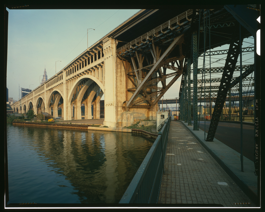
Spanning the Cuyahoga River between Detroit and Superior Avenues, approximately .5 mile west of the Public Square, Cleveland, Ohio UTSU 17/MH260A593580 Quad: Cleveland South J rehabilitated Cuyahoga County Commissioners Ontario Cleveland, Ohio Highway and pedestrian bridge The Detroit-Superior High Level Bridge is a combination reinforced- concrete and steel structure with a total length of feet. The double-deck bridge was designed to carry four lanes of traffic on the upper roadway and six street railway tracks on the lower deck. The center span over the river was a 591-foot three-hinged steel arch of Pratt truss design. At the time of its completion in "the Detroit- Superior Bridge held the record as the third longest steel arch in the country.
The bridge also received attention for its unusual subway approaches beneath the streets at each end of the bridge. The lower streetcar deck was abandoned in Carol Poh Miller, August I978 It is understood that access to this material rests on the condition that should any of it be used in any form or by any means, the author of such material and the Historic American Engineering Record of the Heritage Conservation .and Recreation Service at all times be given proper credit. ^ecOH-6 page i By Cleveland's industrial and commercial growth had made it desirable to have a "high level" bridge over the Cuyahoga River, that is, a bridge high enough to permit,,i v boatsf and/(traffic to proceed without having to stop and wait for the draw to swing.
The Superior Avenue Viaduct, "the pride of the horse-and-buggy era," had become inadequate. Two bond issues to build the bridge sponsored by the City of Cleveland; were voted down. Cn 13 July the Cuyahoga County Commissioners resolved that the county should build the bridge "upon the Cleveland Milan Road" connecting Detroit and Superior Avenues, both state roads. The Commissioners proposed to levy a tax on 2 all taxable property in the county to -finance the structure. On 8 November county residents voted in favor of building the bridge. The County Commissioners resolved to purchase a strip of land 120 feet wide for the new'bridge, and in February 19H the County Surveyor was authorized to prepare complete plans.
J As designed, the Detroit-Superior High Level Bridge was a combination reinforced-concrete and steel structure with a total length of feet and a width that varied from 81 feet, 6 inches at the center to 9^ feetAat the approaches The approach spans flared out in order to accommodate open wells in the center * of the bridge. The double-deck bridge carried a four-lane roadway of the roadway through which 4k* streetcars ./would surface at the ends kk feet, 9 inches wide and two sidewalks of varying width of 12 feet or more. The lower deck was designed to carry six street railway tracks (only four were ever installed), and had a vertical clearance of 15 feet. OH-6 -i - The bridge crossed the wide, flat Cuyahoga River Valley, which was some 100 feet lower than the city grade on each side.
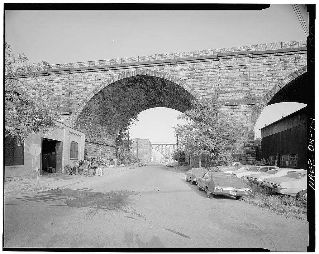
By Federal law, the new bridge had to be designed so that it could be erected without interfering with navigation on the river. A 591-foot cantilevered three-hinged steel arch was chosen for the river span. This was flanked by approach spans consisting of multiple arches of reinforced concrete & 3). There were twelve concrete arqhes, three on the west side of the river and nine on the east side. The arches varied in length; the longest had a clear span of 17^ feet, the shortest a clear span of 58 feet. Each concrete arch consisted of four arch ribs, which supported the beam and slab streetcar deck on heavy spandrel columns* The spandrel columns continued above the lower deck to support the roadway, also of beam and slab construction.
Arch #12 (between Piers #11 and which spanned the Big Four Railroad tracks, required a design different from that of the other arches. In order to avoid the the use of centering, which would interfere with rail traffic, a high-rise curve using three-hinged steel arches for both erection and reinforcement was used. The other arches were reinforced with the usual rods.-* Plans for the bridge were prepared under the direction of Cuyahoga County Engineer Frank R. Lander and County Bridge Engineer A. M* Felgate. It was built under the direction of W. A. Stinchcomb and A. W. Zesiger, who subsequently held these offices, and K. D. Cowen, who served as engineer of construction.
Separate proposals and specifications were drafted for the construction of the substruc- ture, superstructure, and steel arch. These contracts were held by four different firms 1 1) The Great Lakes Dredge & Dock Company, of HAER v -3- Cleveland, constructed the secondary Piers #1 and 2 and #5 through 11, and their contract included setting the grillage material for the cast-steel bolsters, or "shoes," that would carry the steel arch span. 2) The C'Rourke Engineering Construction Company, of Kew York, constructed Piers #3 and 4.
3) The Hunkin-Conkey Company, of Cleveland, "built the east and west abutments and approaches, Pier and all of the superstructure of the bridge on each side of the steel arch span, k) The steel arch was fabricated by the King Bridge Company, of Cleveland, who subcontracted its erection to the Ferro Construction Company, of Chicago.
The proposal and specifications for constructing the secondary piers show that the footings for Piers #i and 2 were built by sinking rectangular caissons in open, dry excavation* Piers #5 6# and 7* on the east side of the river, were sunk considerably lower "in order to provide for a possible diversion of the navigable channel." This was done by constructing a double row of steel sheeting to form a cofferdam and driving the inside sheeting to a base line elevation of -50 (or 50 feet below the average level of the river). Piers #5 through 11 all rested on pre-cast reinforced- concrete piles varying in length from 25 to 50 feet. These were driven with a 5-ton Vulcan hammer. Piles under test were required to carry a load of 60 tons for seven days, with J inch the maximum allowed settlement.
The footings for Piers #3 and 4, which supported the river span,, were built in open cofferdams constructed of inter- locking steel sheet piling, with inner and outer rows spaced 20 feet apart and filled with concrete. These piers were 116 x 80 feet at the base, and rested on stiff blue clay 45 feet below the surface -' . HAER p of the river Work on the bridge began in the fall of Qn 22 January County Engineer Frank R, Lander reported that "the work is progressing in a most satisfactory manner." The excavation for the east, pier had been substantially completed and the bottom was then being leveled for the deposit of concrete.
Samples taken from the excavation showed a "hard, stiff clay" which in his opinion was Q "amply capable to take safely the loads imposed thereon." By 18 June the caisson construction for Piers #1 and 2 was underway, excavation had begun for Pier #3 and Piers #4 and 9 were complete. The concrete piles had been driven for Pier #5. and the test piles for Pier #8 were down and the concrete piles were "about to be driven," The superstructure west of the river was built by means of towers and "Lakewood" chutes. The concreting materials were delivered in scows, then carried by motor truck to the mixing plant, where they were dumped into bins which fed by gravity into a "Lakewood" mixer of 1 cubic yard capacity.
The concrete was spouted from the mixer into a hopper, then transported by truck to the place where it was needed. By the spring of the west approach was nearly completed. An interesting feature of the construction of the bridge*s west approach was the then-novel use of motor trucks to solve the problem of transporting construction materials. All material was brought to the bridge site by water* It was then necessary to haul it up the 12fo grade of the Detroit Avenue hill to the west end of the site. It was essential that deliveries be made with regularity in order to keep the concrete mixers running at capacity.
Scientific 10 HftER OH -6 -5- American reported on the successful use of motor trucks to "build the bridge: The cost of tackling this job without the use of dependable motor trucks would have been prohibitive, engineers say, because it was estimated that in certain phases of the haulage work one truck could make four trips to a team's one, hauling 2^ tons of material while a team </of horses_7 could haul but 3. The trucks performed a double duty, first hauling the cement, sand, gravel, slag and limestone to the mixers, and after it had been properly mixed rehauling the concrete to the forms.
The speed of the trucks was important, because they offered the only means of transportation that enabled the contractors to secure the materials in sufficient quantities to keep the giant mixers busy The whole undertaking affords a remarkable demonstration of the value of the motor truck. . . , The county engineer in charge of the work sayss "We have watched the work of the trucks with great interest and they have been very satisfactory. They have hauled enormous quantities of materials in the shortest possible time and are the only mode of transportation that could be depended upon to keep the mixers busy."- 1 - 2 On the east side of the river, the superstructure was built by means of a double "Lidgerwood" cableway with a span of feet.
The head tower had a height of 180 feet, and the tail tower was 130 feet high. The cableway had an ordinary capacity of 8 tons, although segments of the steel arch centers weighing tons each were also handled. The cables were suspended above and midway between the pairs of arch ribs, thereby enabling the concrete and other material to be hoisted even after the arch ribs were concreted. The concrete plant was located on the east bank of the river opposite Arch #6. The concrete aggregates "Peelie Island" sand and "Kelley Island" crushed limestone were delivered by barges. The materials were unloaded into storage piles by two locomotive cranes equipped with "Owen" clam-shell buckets.
The sand was carried by crane to a bucket elevator, and the stone was transported to its 7 HEAR OH-6 -6- elevator by a belt conveyor operating in a tunnel under the storage pile. The bucket elevators raised the materials 50 feet into bins located above the mixer, One single-cylinder 12 x 20-inch steam engine supplied the power for both the elevators and the stone conveyor belt. The cement was delivered by rail to a cement shed with a capacity of barrels located about 100 feet from the mixing plant. A 36-inch gauge automatic dump car carried the cement up an incline trestle to the mixing platform, where it was recieved by a hopper with a capacity of 6 sacks.
The proper amounts of sand, stone, and cement were obtained by filling the respective hoppers to the desired level, A 6-cubic yard steam-driven "Smith" mixer, located on the floor beneath the mixing platform, was used for all of the concrete. 'The mixer dumped into a hopper directly above the 36-inch gauge track that served the cableway. One large flat car accommodated two 3-cubic yard "Haynes" buckets. This car was hauled by one drum of a reversing hoisting engine to various points under the cableway, as needed. When both cables were in use, as many as 55 cubic yards of concrete could be placed in one hour. A central boiler plant of 200 h. p. powered the cableway engines, the mixer, car hoist, bucket elevator hoist, and one of the locomotive cranes.
As far as possible, the forms for the concrete were made in sections at a central saw shed. This 25 x ^0-foot shed consisted of a roof supported on four posts and open on all sides. It was equipped with a swing cut-off saw, a rip saw, a band saw, and a "Handy" woodworker, all electrically driven. Only three sets of arch-rib forms were needed (each of the larger arches was centered by using _7- HAER OH-6 three-hinged steel arches). These were made in 12-foot sections of matched 2 x 6-inch sheeting, laid perpendicular to the arch rib and nailed to 3 x 6-inch studs braced two feet apart on centers. Six-by-six-inch whaling timbers placed perpendicular to the arch ribs on 5-foot centers were bolted above and below the concrete arch rib.
When necessary, extra bolts encased in tin tubes were run through the concrete. After the arch rib had set, the side forms were removed with the aid of the cableway and transferred to their new positions without lowering them to the ground. "A rib has been stripped and the forms again set up in five hours," Sngineering n and Contractmg reported* J The larger arches were centered with three-hinged steel arches resting on a steel-covered runway supported from the concrete pier footings by steel columns. Six sets of steel centers were used* which permitted work to proceed on three different pairs of ribs at the same time.
After the arch ribs were poured and had set for about fourteen days, the centers were lowered by a toggle adjustment and rolled over into place for the other two ribs of the span. It was found that a settlement of 2 inches occured at the crown of the arch ribs as they were built, so this was taken into account in setting the steel centers. * Fig* DSB Photo-1) shows the subway deck and Arch #12 as they appeared shortly after construction. Probably the most significant aspect of the Detroit-Superior Bridge was the design and construction of the 591-foot steel arch that spanned the river.
This was "one of the most important examples of a spandrel-braced, three-hinged steel arch truss bridge yet built," according to Engineering Record : Its most notable features are the general outlines of the trusses, the details of important members, the Q OH-6 unusual truss and floor connections, the double- deck arrangement with four cantilever .extensions providing for sidewalks, the wide driveways ^roadways/ and six electric car lines, the heavy loads assumed and the various combinations provided for, and the combination of carbon and nickel steel and range of unit stresses adopted for them.
1 " The steel arch span consisted of Pratt trusses, the main members of which were box sections made up of plates and angles connected with lacing bars,(DSB Lateral bracing was provided in the plane of each chord member. The curved top and bottom chords of the arch were spaced 4-9 feet, 3 inches apart on centers. The trusses varied in depth from 20 feet at the crown to 91 feet, Z\ inches at the ends. The span was divided into twenty-four 2^ foot, 7-inch panels with one vertical and one diagonal member for each panel. Except for the crown and skew-back hinges, all connections were riveted. The lower-chord crown hinge joint was made with a 12-inch pin and the lower-chord skew-back hinges were made with 16-inch pins engaging cast-steel bolsters anchored by the grillage to the masonry piers.
The upper deck of the main span was located at about the level of the ends of the top chords, intersecting the lower chords at about the fifth panel point from the ends. The span carried an upper roadway kk feet, 9 inches wide; two 15-foot sidewalks were cantilevered outside the arch. The lower deck, 80 feet wide overall, was of open stranger construction and carried four tracks between the arch span and two cantilevered tracks. Both the upper and lower decks between panel pointst5 -15 were located wholly below the bottom chords and were suspended from the latter by vertical eyebars. At panel points L5 the upper deck intersected the lower chords and *'$ HRER OH-6 its floorbeams were pin-connected to the vertical posts of the main truss.
The upper deck floorbeams were single-web plate girders at these points, passing between the built channels composing the vertical posts and extending beyond them to provide the cantilevers for the exterior sidewalks, Syebars, pins, and truss members (except the lacing bars and stay plates) were made of nickel steel. The floor beams, stringers, and all bracing were made of carbon steel. Cast steel was used for the bolsters supporting the arch, structural steel for the grillage. Nickel steel rivets were used in the arch, 17 carbon steel rivets m the other portion of the bridge. The steel arch span was designed to carry a load of per linear foot of bridge, plus impact varying for different positions from 14 to 36 per cent.
Stresses due to a 24-ton truck, plus impact, were assumed in designing the floorbeams.,- stresses due to a 60-ton streetcar, plus impact, were assumed in designing the lower-deck floorbeams and. hangers. Working stresses allowed for the nickel steel truss members in tension were per square inch* for those in compression, per square incii. This was increased about 30 per cent for wind and erection stresses 1 S The arch trusses and part of the floor, together with the lateral and transverse bracing, were erected from each river pier as a cantilever in order to avoid interfering with navigation on the river. The principal work was done by a timber top-chord traveler carrying two 25-ton stiff-leg derricks. The total weight of each traveler with derricks and. a 52 h. p.
engine was about 70 tons. The traveler rolled on a track made of two 8 x 16-inch timbers laid flat side by side, resting on 8 x 8-inch by 34-foot ties laid on the top HAER OH-6 chord of the arch. Material for constructing the arch was hoisted from scows in the river. The travelers worked forward from both piers until they met at the center of the arch. The erection of each arm of the arch was "begun from 90-foot steel towers erected behind the abutment piers. The towers were erected with the aid of a gin pole. (This is a vertical pole guyed to the ground by cables; it is used in connection with blocks and tackle for raising weights.) After the gin pole was used to erect the east tower, it was dismantled and re-erected at the west pier to build the west tower.
The traveler and its derrick were erected on these towers. Eyebar backstays held the half-arches in place until 19 they were joined at the center. The erection of the steel arch began on 29 July It was completed on 8 October of the same year. On that day , the two arms were lowered beginning at a.m. By 2i23 with a 2-hour intermission, the arch-was closed. Telephones were used to synchronize the action at each hoisting engine , which turned the toggle .screws that closed the arch. The two arms of the.arch lined up within 1/8 20 of an inch. The small difference was adjusted "by a cable." Cuyahoga County Engineer W, A, Stinchcomb*.
who supervised the com- pletion of the bridge*, later wrote : It was quite a site to watch the two great trusses, 290 feet long and weighing about tons each, slowly move into position. Like the hands of a watch, no movement could be seen, but the space between the two ends gradually lessened until the ends touched and the arch took its final position. . . .
The work was so accurately fabricated and erected that the alignment and elevations were almost exact..21 The double-deck floor system was erected from the center of the bridge outward as the travelers returned to the piers Photo-2), HAER OH-6 The material was hoisted from scows in the river and placed in the following sequence: First, the 8 x l-3/8-inch eyebar hangers were placed in the arch chords, N 7 ext, the pin-connected floorbeams of the upper deck and the "built-up hangers for the lower deck were erected. The lower-deck floorbeams were placed, then riveted to the hangers. Erection of the stringers and bracing followed. By 5 Novemebr all of the steel about tons had been placed. The metal work was then cleaned and painted two coats (one coat had been applied in the shop). ^ Fig.
Photo-3 ) shows the' completed arch and floor system as it appeared during the winter of Both the steelwork and the travelers used to erect the arch were fabricated by the King' Bridge Company. Harry Fuller, chief engineer for the company, was in charge of its, design and fabrication. The actual work of erecting the arch was subcontracted to the Ferro Construction Company. F. F. Buck, who was in charge of field work for Ferro, supervised its construction. There are no published accounts of the finishing work on the bridge. Photographs and drawings show that there was a spindle and post balustrade, made of marble.
Decorative marble pylons originally stood on the upper roadway at each of the four points of intersection with the steel arch span ; ^treet lights of the "Cleveland lantern' intervals type were s_paced at uniform A on each side of the bridge. * * The original plans called for carrying the streetcars from the lower deck back to street level by constructing inclines and HAER No. OH-6 i3 open wells at the center of the approaches. This idea was abandoned in February after the Cleveland City Plan Commission resolved that "traffic conditions at the east and west ends of the new high- level bridge t . . are such that both approaches should be provided 2< with subways . . .." J County Engineer Stinchcomb proposed that short subways be built for a length of several hundred feet at each approach.
The Cuyahoga County Commissioners, noting that construction of the approaches as originally planned would "materially interfere with the utility /of the bridge/," endorsed the new plan. The revised plans show that, on the east side of the bridge, the streetcar subway continued for a distance of I85 feet to a point on Superior Avenue just beyond W, 9th Street, On the west side, there were two subways. One continued west under Detroit Avenue to W, Street for a distance of 725 feet ' *^~ ^ M % another subway continued south beneath W. Street to Church Avenue for a distance of 5^0 feet & 8). Streetcars entered the subways through open wells located in the center of the roadways Photo-y). There were four pedestrian entrances to the subway at the intersection of Detroit Avenue and W.
Street (one of these was located in the Forest City Building on the southwest corner) and one on the south side of Superior Avenue at the bridge's east approach. The Electric Railway Journal described the underground system \ At each end of the bridge is a paved area large enough to accommodate several cars on each track, the floor being of stone blocks grouted with cement. The tracks of each line are separated by a light fencing Long flights of easy steps lead from the street level to the track deck with attractive housings over the stairways at the street level. o* % - HAER Noi-OH-6 The "attractive housings" were small wood frame buildings with hipped roofs .
Below ground, the station and tunnel walls were supported "by reinforced-concrete retaining walls, while a system of closely spaced beams and columns supported the upper roadway. Each station consisted of a waiting area, boarding platforms, circuit control and storage rooms, and public toilets. The stations featured white glazed tile walls with recessed lighting and were very plain in appearance Photo-.? - ) . Tunnels under the tracks at both stations gave pedestrians access to east-, west-* and south-bound'trains. ' "Especially fortunate is the opportunity for loading and unloading cars away from street level, which has been taken full advantage of," Electric Railway Journal concluded.
The railway installation was constructed by the Cleveland Railway Company, with track work under the direction of Charles H. in Clark and overhead work under the direction of L. P. Crecelius.*'' The Detroit-Superior High Level Bridge was opened to automobile traffic on Thanksgiving Day, Because it opened during wartime, no ceremony marked the occasion. The first streetcar crossed the bridge on Christmas Eve of the same year. The car carried some fifty persons, including Cleveland -vayor Harry L. Davis, County Engineer Ctinchcomb, Street Railroad Commissioner Fielder Sanders, and Cleveland Railway Company engineer Charles Clark.
The car left W, Street and headed east over the bridge shortly before * 'Wonderful,' and 'it's getting more and more like -\'ew York in Cleveland* were some of the ejaculations heard in the car," according to the Cleveland Plain Dealer. 2 9 HAER No. OH-6 Cleveland was proud of its new bridge which, upon completion, was the longest double-deck, reinforced-concrete highway bridge in the world. The bridge was celebrated in post cards of the period (D B Photo- t i) .
Scientific American declared that the 591-foot steel arch represented "the new school of American engineering which has eliminated the draw-bridge from our municipal economy along with the grade crossing and the ferry-boat,"^ But the bridge, built at a final cost of , served for just ten years before cries were heard to relieve -Igfe traffic congestion t hat had d e v elo ped . Clearly its planners had not counted on the proliferation of the automobile that U&AN occur during the decade of post-war prosperity. In there was a proposal to pave and use a portion of the lower streetcar deck for auto traffic. County Bridge Engineer A. w, Felgate reported that the unused portion of the lower deck could be opened at a cost of fit , 1 0 and that it could accommodate automobiles an hour.
The Cleveland Times supported the proposal, saying it would give relief to the "almost hopeless traffic congestion, 1 " * j/othing was done about the proposal, and the problem of traffic coagestion persisted. The completion of the lorain-Carnegie { -'ri i.e one half mile to the south offered some relief, as did - % . % '' "air Avenue Bridge The construction of Bulkley Boule \r. connection with the latter bridge necessitated the widenir.r :' the west approach to the Detroit-Superior Bridge. The wooden subw ,v house on the northeast corner of Detroit Avenue and W. -. tree* was razed, the stairwell to the subway was relocated, and a new sandstone subway house HAER No. OH-6 32 was built.
J The original designs of those who planned the Detroit-Superior High Level Bridge were increasingly undermined by the growing popularity of the automobile and the subsequent abandonment of streetcars by anyone who could afford to do so. '[he trend continued unabated. By the "attractive housings" over the subway entrances had become deteriorated and vandalized and subway station photographs taken during this period show that they had become dirty and neglected. -^ On ^_ December^ the Cleveland Plain___Dealer reported .Vayor Anthony J. Celebrezze's proposal to use the lower bridge deck exclusively for autos. The idea was dismissed by Cuyahoga County Engineer Albert S.
Porter as "engineered murder," although a trial roadway was established for a brief time during February Meanwhile, Cleveland's trolley age officially ended on ^_January *% with the' last free ride celebration from Public Square to W. Street and Bridge Avenue. The last streetcar on the Detroit Avenue line had run on o August A 1 9 51* "the last car on the W.
Street line on if August / i In ~/^Uy the Cleveland City Council passed an emergency ordinance granting its consent "that Superior Ave, be improved by filling in the existing street car wells leading to the Detroit-Superior Bridge."^ Closure walls were constructed at the ends of the subway tunnels and the open wells were filled with gravel and paved over in Tk spandrel arches closest to both approaches were closed up with cinder block to keep out trespassers. The stairwells to the subways were closed and covered , and the wood frame station houses were removed. In 19^5i consulting engineers hired by the county to make an inspection and rehabilitation study of the Detroit-Superior Bridge --HAER NO.
OH-6 reported that "Because of ape and corrosive atmosphere the bridge has deteriorated to the point that normal maintenance is no longer adequate and the structural stability of some members has become questionable." The engineers noted that the upper deck slab and sidewalk had failed in some places and had been covered with steel plates. "Extensive rehabilitation is needed in the near future if 37 the bridge is to be continued in service," they wrote. ' The Detroit-Superior Bridge was rehabilitated in The roadway was widened to six traffic lanes, from 44 feet, 9 inches to 72 feet, and the sidewalks were reduced from Ik to 5 feet on each side. The extra lanes were added by cantilevering them on the outside of the steel arch span.
The upper deck roadway slab, sidewalks, railings, and light standards -rfi were replaced, and the ornamental pylons were removed. Aside from normal maintenance, no further work is planned for the bridge. Cuyahoga County Bridge Engineer Eugene A. Halupnik predicts that it will continue in service through the 19POs. 3 8 At the time of its completion, Engineering flews noted that the "main novel features" of the Detroit-Superior High Level Bridge were its double-deck design of concrete arches, its unusual subway approaches, 30 and the "very large steel arch" across the river. Engineering Record reported that the Cleveland bridge held "third place in span length in this country, being exceeded only by the Hell Gate arch kO and the Niagara arch." - " *HAER No.
OH-6 Tn later years, the records set by the Detroit-;.uperior Fridge, 'ew York City's Hell Gate bridge, and the *iagara-^lifton Bridge over the " T i agara Kiver were surpassed by ever, longer steel arches. The Bayonne Bridge over the Kill Van Kull linking ;,ew Jersey and Staten Island, and the ivicKees Rock Bridge at Pittsburgh are two important examplesi the former bridge, with a clear span of feet, still holds the record as the longest steel arch in the world.
In recent times, steel arches have been used frequently for short highway and pedestrian bridges but are now rarely employed for very long spans \ the flat terrain usually associated with navigable waterways makes it difficult to gain the necessary clearance and, according to Carl Condit, "the arch must be raised tn such a height that the provision of proper approaches becomes highly expensive , . .." The final importance of the Detroit-Superior Bridge to Cleveland engineering lies not in the-records it set during the early years of long-span steel arch construction, but in its impact on the city's growth. "'he bridge prompted a real-estate boom on Cleveland's West Side and in the suburb of Lakewood.
Cleveland historian William Ganson Rose links Lakewood's growth directly to the opening of the bridge, which facilitated travel to downtown and points east. The Detroit- c u perior High Level Fridge is still, an important river crossing to anyone living or working on the city's West Side. Finally, the story of its planning, construction, and later modification succinctly illustrates many of the cultural and technological forces that shaped this city during the years between and ' '* --HAER No. OH-6 Detroit-Superior High level Bridge--fcotnotes V/illiam Ganson Rose, Cleveland! The ;",akir.g of a City (Cleveland and -lew Yorki The World Publishing Company, p.
In a 29-member Bridge Committee published a map proposing the construction of a high level bridge that would link Franklin Avenue on the west side of the Cuyahoga River with Superior Avenue on the east. The map, titled "The New High Level Bridge," is located in the library of The Western Reserve Historical Society, Cleveland. It was prepared by J. E. Davis & Son, Civil Engineers (Cleveland: P February 2 (Cuyahoga County) Commissioners' Journal Record, Vol. 27, pp. Cuyahoga County Archives, Cleveland, Chio. 1 , <* v - ^Commissioners' Journal Record, Vol 28, pp.
13-I^A A taxpayers' suit, filed to restrain the county from building the bridge on the grounds that the proposed structure did not follow the crooks and turns of the old State road, and that a viaduct connecting one high bank of the river with another was not a "bridge" within the meaning of the statute, was promptly dismissed. See E, J. Landor, "The High level Bridge," Proceedings of the Ohio Engineering Society ^33 lie. The constantly varying width of the approaches made both design and construction of the bridge difficult, according to Cuyahoga County Fngineer W, A. Stinchcomb, because "no two beams were of the same length, requiring separate calculation and forms for each as well as varying column loads." See "The Detroit-Superior and Brooklyn- ** + < HAER No.
OH-6 Brighton Bridges," Proceedings of the Ohio Engineering Society 3? I12*K ^"Detroit-Superior Bridge, Cleveland, Ohio," Engineering '.ews 71 (18 June 1I35O-I35I. Because of the angle of the railroad right of way, two ribs of this arch were advanced ten feet beyond the other two in order to obtain the necessary clearance. Engineer rtinchcomb ("Detroit-Superior and Brooklyn-Brighton Bridges," p. notes that, as a result, "The construction work at this arch was somewhat complicated." "Detroit-Superior Bridge," p. _~~ The Hunkin-Conkey Construction Company, incorporated in succeeded a partnership founded by Samuel and William J. Hunkin.
Rose ( C leveland , p, writes: "Having built many of Cleveland's larger industrial plants, the Detroit-Superior High Level Bridge, and Akron rubber plants, in addition to hotels, banks, power plants, and office buildings, the War department engaged the company, prior to World War II, to construct the sever.ty-million-dollar Ravenna Ordnance Plant. In the corpany was engaged in the largest railroad construction and re- location job in the country for the Pennsylvania Railroad east of Pittsburgh," 7 Cuyahoga County, Ohio, Frank R. lander, County Engineer, "Proposal, Contract and Specifications for Secondary Piers, Detroit- Superior Bridge," pp.
All of the proposals, contracts, and specifications for the Detroit-Superior Bridge are located in the Office of the Cuyahoga County Engineer, Standard Euilding, Cleveland, <"'hio, o Stinchcomb, "Detroit-Superior Bridge and Brooklyn-Brighter ' '" H&ER No. OH-6 XI Bridges," pp. Commissioners' Journal Record, /ol. 3 2 , p. 67. "Detroit-Superior Bridge," % p. 11 "Methods and Equipment Used in Constructing the Superstructure of the Detroit-Superior High Level Bridge in Cleveland, C," Engineering and Contracting kk> (? July 19l4)il0-ll. Unless otherwise noted, details of the construction of the bridge superstructure are taken from this article. '""Cleveland's New Bridge The Role of the Motor 'I ruck in Its Construction," Scientific American , 25 Movemebr p, U80.
13 % f e thods and Equipment," p. 12, 1^ The use of three-hinged steel arch centers had been pioneered by Cleveland consulting engineer Wilbur Watson. See Carol Poh iviller, "The Rock River p r idge Triumph in Concrete," IA, The Journal of the Society for Industrial Archeology 2 i 50, ''Each arch consisted of four ribs. The steel centers were placed for two arch ribs in each of three spans simultaneously. According to engineer Stinchcomb, variations in the size of each arch was made up by removing certain sections of the steel centers. See "Detroit-Superior and Brooklyn^Brighton Bridges," p. "Vain Span of Detroit-Superior Bridge over Cuyahoga River at Cleveland," Engineering Record 70 (28 Movember 17 Cuyahoga County, Ohio, Frank R.
Lander, County Engineer, "Proposal, Contract and Specifications for Steel Arch, Detroit- Superior Bridge," p, 6. ' *' HAER No. OH-6 i ft Stinchcomb, "Detroit-Superior and Brooklyn-Brighton Bridges," p. A detailed account of the calculations made for assumed loadings and wind stresses can be found in " ain Span of Detroit- Superior Bridge, " ' c i t ed above. 1 o ^Diagrams of the gin pole and the erection traveler can be found in "Erection of Steel Arch Span, Detroit-Superior Viaduct," Engineering News ?U (19 August 20 "Detroit-Superior 591-Foot Steel Arch Successfully Swung by Toggle Adjustment," Engineering Record 72 (25 December Apparently the "toggle adjustment" used to close the arch of the Detroit-Superior Bridge differed from the method used for New York City's Hell Gate Bridge.
The hinged arch ribs of the Hell Gate Bridge, which also were erected by cantilevering them out from towers, were rlosed by hydraulic jacks of 2,500-ton capacity. These were used to lift the halves of the arch into exact alignment, according to Carl W, Condit ( A m erican Building Arti The Twentieth Century (:.ew York 1 Oxford University Press, p. Unfortunately, the "toggle adjustment" used to close the Cleveland arch is not described clearly enough to permit further elaboration here. 21 "Detroit-Superior and Brooklyn-Brighton Bridges," p. 22 " Detroit-Superior 591-Foot Arch," p. 23 -'"Proposal, Contract and Specifications for Steel Arch," p. 7. "Detroit-Superior 591-Foot Steel Arch," p. 79L jhe full text of the resolution can be found in the Commissioners' Journal Record, Vol. 36, p.
26 Ibid., pp. HAER No. OH-6 St 27 "Klectric Railway Construction on the Detroit-Superior Bridge," Electric Railway Journal 52 (27 July Rose, Cleveland, p. 2"5 December* ^"Cleveland's New Bridge," p. 'Yj^February -* This building is now part of the Cuyahoga County Engineer's West Superior maintenance yard, ^'Photographs of the stations are located in the "Detroit- Superior High Level Bridge" file in the library of the Cleveland Press , 901 Lakeside Avenue, Cleveland, Ohio. ?4 T b i d . A photograph in the Cleveland Press collection dated \y FebruaryV1954 illustrates the trial use of the bridge subway for autn traffic. ^Harry Christiansen, Trolley Trails Through Greater Cleveland and orthern Ohio From to Today (Cleveland* The Western Reserve Historical Society, p. ^6. J Ordinance o.
V) z' /7 ^^ j JSLA- ~ ;i- f- j % ^'Howard, v e edles f lammen & Bergendoff, Consulting Engineers, "Detroit-Superior Bridget Inspection and Rehabilitation Studies," Cleveland, /'arch ( p ; i meographed) , p. 1. This report contains a complete summary of the condition of the bridge in J Interview, Office of the Cuyahoga County Engineer, Cleveland, "HAER No. OH-6 Ohio, l^July 39. ^0 h\ hz Detroit-Superior Fridge," p. "Detroit-Superior 591-Foot Steel Arch," p. 790 Condit, American Building Art , p. Cleveland, p. DJH RiHTSiJH'KlOR KIGH Uf.VBL BRIPGK HAER No. OH-6 ^cifeu XEROGRAPHIC COPIES OP COLOR TRANSPARENCIES HISTORIC AMERICAN ENGINEERING RECORD NatiooaJ Park Service U.S. Department of the Interior Washington.
 Block
Block