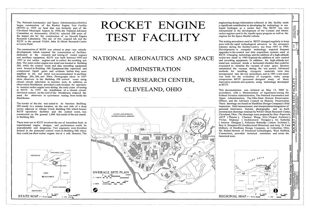
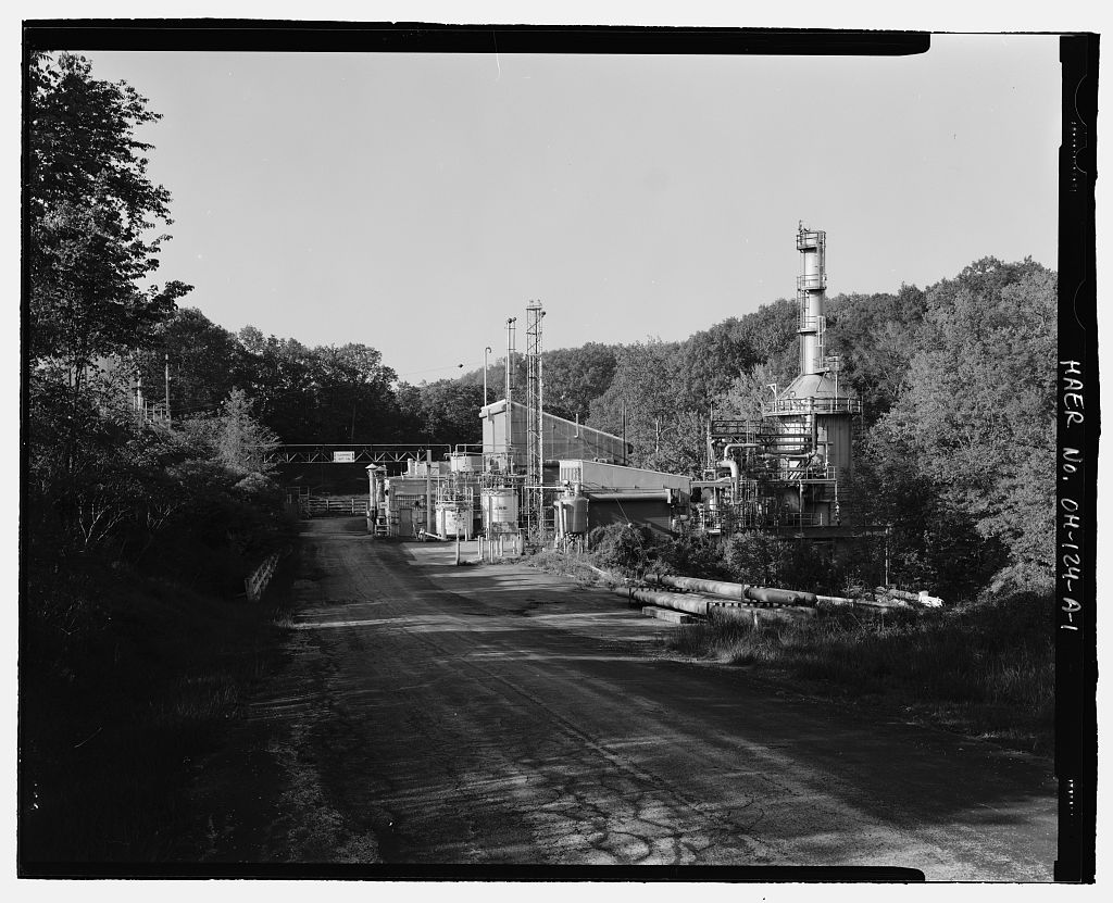
This documentation was initiated on May 15, in accordance with a Memorandum of Agreement among the Federal Aviation Administration, National Aeronautics and Space Administration (NASA), The Ohio State Historic Preservation Officer, and the Advisory Council on Historic Preservation. The City of Cleveland plans to expand the Cleveland Hopkins International Airport. The NASA Glenn Research Center Rocket Engine Test Facility, located adjacent to the airport, must be removed before this expansion can be realized. To mitigate the removal of this registered National Historic Landmark, the National Park Service has stipulated that the Rocket Engine Test Facility be documented to Level I standards of the Historic American Engineering Record (HAER).
This project was initiated to fulfill that requirement. Historians: Robert C. Stewart Historical Technologies, West Suffield, Connecticut Dr. Virginia P. Dawson History Enterprises, Cleveland, Ohio Roy A. Hampton III Hardlines Design Company, Columbus, Ohio Historic Context - Planning and Development of Rocket Testing at Lewis Flight Propulsion Laboratories: Research into liquid-fueled rockets in the Cleveland area was conducted as early as under the aegis of the Cleveland Rocket Society. While the Society was a group of amateurs, a German engineer, Ernst Lobell, headed a team that successfully launched several liquid-fueled rockets starting in These rockets, however, were not destined for space, since Lobell envisioned using rocket vessels for speeding up intercontinental mail deliveries.
1 The costs and facilities necessary for advanced research were beyond the capability of individual researchers and amateur societies, and only the government or corporate sectors could therefore complete serious rocket research. The government and major corporations, however, were not developing rocket engines at the time. Instead, their efforts were focused on developing advanced piston-engine designs. The progression into jet and rocket engines by government and corporate laboratories was consistent with the advance of technology. In the late research into advanced aircraft engine design was centered in governmental laboratories in Great Britain and Germany.
Wright Aeronautical Corporation and Pratt & Whitney, the major American engine manufacturers, produced fine commercial engines but were reluctant to commit major funding to advanced engine development. 1 Frank H. Winter, "Lighting the Fuse," Timeline (October-November ROCKET ENGINE TEST FACILITY HAER No. OH-124 Page 3 Several aeronautical engineering pioneers, including George W. Lewis, Director of Research for the National Advisory Committee on Aeronautics (NACA), saw a critical need for a government- funded laboratory devoted to engine development. He and others successfully managed to secure federal funding for an engine research laboratory. From the Cleveland Municipal Airport had expanded to more than acres.
During this period the airport hosted the National Air Races, and the western portion of the airport was used as a parking area during the races. In NACA decided to build its Aircraft Engine Research Laboratory in Cleveland on 200 acres of the municipal airport. In April the Aircraft Engine Research Laboratory was renamed the Flight Propulsion Research Laboratory to reflect its role in propulsion research. The name was changed again the following year to the Lewis Flight Propulsion Laboratory (herein referred to as Lewis Laboratory), in honor of George William Lewis.2 In the late and early the U.S. military was responsible for aggressive research in rocket propulsion.
3 As part of this development, portions oflaboratories at Wright-Patterson Air Force Base that had tested jet propulsion technologies during World War II were converted into rocket engine test facilities from 4 Concerns about national security guaranteed that the Army, Navy, and Air Force received ample funding for propulsion research and development. In contrast, funding for propulsion development by NACA remained tight through the early l 5 As part of its mission as a nationwide laboratory focused on aircraft engines, Lewis Flight Propulsion Laboratory began rocket propulsion research as early as There was strong interest in rocketry for U.S. military applications during the early Cold War years due to the success of the German V-2 rocket during World War II.
A rocket propulsion section was established at Lewis Flight Propulsion Laboratory in Between and the early a large amount of research at the Lewis Laboratory rocket lab focused on the improvement of existing turbojet technologies. Although NACA management during the late was uncomfortable with the organization taking a more aggressive role in rocket propulsion development, the Lewis Laboratory rocket lab completed some research on rocket fuel development during the late Rocket propulsion research completed at Lewis Laboratory in the late was circulated to the Navy Bureau of Aeronautics, Air Force Materiel Command, 2 George W. Lewis ( was a leading proponent for basic research at the National Advisory Committee on Aeronautics (NACA).
He strongly believed that practical testing of concepts was the way to acquire useful knowledge, and he was an active participant in formulating research policy and NACA's early emphasis on engineering rather than basic aeronautical science. 3 Virginia P. Dawson, Engines and Innovation (Washington, National Aeronautics and Space Administration, l 99 l ). 4 Hardlines Design Company, "Historic Documentation of Buildings 79A-C and Building 95, Wright-Patterson Air Force Base," on file at Hardlines Design Company, 5 Dawson, Engines and Innovation, ROCKET ENGINE TEST FACILITY HAER No. OH-124 Page4 and other U.S. military organizations. 6 In the late researchers at Lewis Laboratory became interested in experimenting with hydrogen rocket technology.
In Lewis Laboratory received its first formal funding appropriations for rocket research, possibly following intelligence reports of Soviet advances in rocket technology development. At that time, Lewis Laboratory had a series of cinder-block World War II-era rocket test cells, and four larger cells that had been built later using laboratory operation funds. 7 When the initial request for construction of the Rocket Engine Test Facility was made in much of the rocket research at Lewis Laboratory was related to military applications. This was still true in when construction began on the Rocket Engine Test Facility. 8 It was only after the successful launch of Sputnik by the Soviet Union in that the space travel potential of Rocket Engine Test Facility research was more strongly emphasized.
9 Liquid hydrogen had been proposed as a rocket fuel as early as and Tsiolkovsky's Treatise on Space Travel advocated the material as an ideal fuel. The American rocket pioneer Robert Goddard recognized its potential. Goddard calculated that liquid hydrogen, even diluted 2: 1 over that required for complete combustion, would increase the total rocket's mass by only 11 percent. 10 As early as researchers at The Ohio State University produced a liquid-hydrogen-fueled rocket.
11 Unfortunately, there were no laboratories or pilot plants available immediately after World War II capable of doing research on liquid hydrogen as a rocket fuel, although experiments using liquid hydrogen and gaseous oxygen in rockets were completed at Ohio State from April 2, until May 29, Aerojet General Corporation was also running similar tests in California from as was the Jet Propulsion Laboratory from 12 The U.S. Army carried out major programs of rocket research in the early to mid-l at Redstone Arsenal, near Huntsville, Alabama. This work focused on missile development. Two major new weapons resulted from research completed during World War II. The United States developed the atomic bomb, while the Germans developed the a liquid-fueled, medium- range, rocket-powered missile.
In the late the U.S. Army sought to make the atom bomb 6 Virginia P. Dawson, "History of the Rocket Engine Test Facility at NASA-Glenn Research Center" (draft). On file at Hardlines Design Company (February 19, 7 Dawson, Engines and Innovation, 8 Ibid., 12, 25. 9 Ibid., 10 Robert H. Goddard, Rocket Development (New York: Prentice-Hall, Inc., 11Virginia P. Dawson, Rocket Propulsion Research at Lewis Research Center (Cambridge, Massachusetts: Lewis Research Center, July 1. 12 John Sloop, Liquid Hydrogen as a Propulsion Fuel, (NASA Special Publication No. 2. ROCKET ENGINE TEST FACILITY HAER No. OH-124 Page 5 lighter and the V-2 engine more powerful, so that a missile capable of carrying an atomic warhead could be developed.
By an American team of scientists, which included many of the Germans who had worked on the achieved this goal. The team reduced bomb weight to pounds, and they developed a prototype rocket engine capable of producing 333 kilonewtons pounds) of thrust. The Army continued to develop what was called the "Redstone" missile, and spent millions of dollars to improve guidance systems and rocket reliability. The Redstone was deployed to NATO troops in West Germany in Post-design phase rocket engine development generally follows three stages: engine testing, static rocket testing, and experimental launches. The second stage requires that the rocket be securely anchored in a "static test stand" where its performance can be measured and evaluated.
This requires a facility to house the stand, an infrastructure to supply reactants, and instrumentation to monitor rocket performance. In the Army realized that further development of the Redstone would require construction of a more sophisticated test stand than the primitive rigs in use during this period. A law passed by Congress, however, restricted the research and development funds that could be spent to build facilities. Rather than wait the usual four years required to appropriate funds to construct a facility, Redstone engineers designed and built an "interim test stand" for This amount was the maximum that could be spent without congressional approval.
By a permanent test stand, the "Static Test Tower," had been built, but the Army opted to continue operations at the interim test stand. 13 Part of the reluctance to fund additional rocket research through the military may have come from President Eisenhower's inclination to create a new agency for space exploration, the National Aeronautics and Space Administration (NASA), out ofNACA. The Redstone and its supporting infrastructure were designed for the use of alcohol and liquid oxygen as propellants. The interim test stand was equipped with a steam-powered pump to force the reactants into the combustion chamber. Steam was generated for the pump by using potassium permanganate to cause hydrogen peroxide to decompose.
14 During the period when research on the Redstone was ongoing at Huntsville, scientists at NACA-Lewis Research Center were exploring the development of liquid hydrogen as a fuel. Steady supplies of liquid hydrogen were unavailable during the post-war period. Consequently, early research focused on un-symmetrical dimethyl hydrazine as a fuel and oxidizers such as hydrogen peroxide, chlorine trifluoride, liquid oxygen, nitrogen tetroxide, and liquid fluorine. 15 These reactants were toxic and produced toxic by-products. Any facility using them required the implementation of methods for the safe handling and disposal of waste. 13 Historic American Engineering Record (HAER), National Park Service, U.S. Department of the Interior. "Marshall Space Flight Center, Test Stand." HAER No.
AL-129-A, Historic American Engineering Collection, Library of Congress, Washington, 14 Ibid., 32. 15 lbid. ROCKET ENGINE TEST FACILITY HAER No. OH-124 Page 6 In the early the Lewis Laboratory acquired a hydrogen liquefier, and many tests were run in the Rocket Lab Test Facilities. Hydrogen/fluorine engines were tested in Cell 22, which was equipped with a scrubber. 16 However, rocket staff at Lewis Laboratories began to plan a large rocket engine test complex better suited to testing liquid hydrogen technologies. At first, they planned this propulsion laboratory for a remote location in the western United States, but they eventually decided to develop a smaller rocket test facility at Lewis Laboratory.
Lewis Laboratory scientists requested authorization to construct a test facility for evaluating high- energy propellants and rocket engine designs. NACA approved this request in The test laboratory that resulted from this approval was Lewis Laboratory's Rocket Engine Test Facility. 17 Construction drawings were produced for the Rocket Engine Test Facility from and construction was completed between The facility included a test cell and ancillary buildings dedicated to the testing of full-scale rocket engines, and researchers soon focused on the use of liquid hydrogen as a fuel.
The complex was located on a ten-acre site within a forty- acre area at the southern end of NASA's Glenn Research Center, a location locally known as the "South The facility was designed to permit up to three minutes of operation at a thrust of eighty-nine kilonewtons pounds) of thrust. However, on rare occasions, tests were run at 311 kilonewtons pounds) of thrust. In this facility was the largest high-energy test facility in the country capable of handling liquid hydrogen and other liquid fuels that could produce toxic exhaust. The construction of a large scrubber to remove pollutants was unique at the time.
The complex was finished in the fall of at a cost of million, and originally consisted of two major components: a control center housed in Building and a test cell in Building An observation blockhouse was also included in the original construction campaign. Support structures added subsequently included Building a propellant transfer and storage facility built ca. and Building which was built in to accommodate a cryogenic vaporizer and compressor. This facility was an integrated laboratory, designed and built to perform specific experimental functions. As such, it differed from the more developmental missile-oriented facility at Redstone and other similar developmentally oriented facilities operated by the military.
18 16According to George Repas; cited in NASA-Glenn Research Center, "Comments on the Rocket Engine Test Facility Historic American Engineering Record Documentation" (January 24, 5. 17 Dawson, Engines and lnnovation, l 51. books/butkowsky4/space8.htm. Other major centers of rocket propulsion development in the late and included White Sands Missile Range and Edwards Air Force Base. Rocket propulsion test stands built at White Sands in the late and included the" lOOK" and Static Test Stands, both completed in l and the Test Stand" built in However, these stands accommodated static propulsion systems testing of full-scale missiles rather than testing of single engines, as was the case at the Rocket Engine Test Facility.
As at Redstone Arsenal, these White Sands test stands were developmentally oriented, in contrast to the strong research orientation of the Rocket Engine Test Facility. ROCKET ENGINE TEST FACILITY HAER No. OH-124 Page 7 Contemporary NASA Rocket Testing Facilities: The Rocket Engine Test Facility at the Glenn Research Center at Lewis Field was one center among several in NASA's facility inventory. At present the John C. Stennis Space Center in Hancock County, Mississippi, manages NASA's rocket propulsion testing programs. It oversees facilities at the Marshall Space Flight Center in Alabama, the White Sands Test Facility in New Mexico, and the Glenn Research Center's Plum Brook Station in Sandusky, Ohio.
All main engines used on the Space Shuttle undergo acceptance testing at the Stennis facility. In addition to acceptance testing, Stennis is equipped to test developmental rocket engine components in a complex of seven separate test cells equipped with facilities for handling ultra-high-pressure gases and high-pressure cryogenic fluids. The George C. Marshall Space Flight Center in Huntsville, Alabama, is currently NASA's primary center for developing space transportation and propulsion systems. Its facilities include a Combustion Research Facility, Component Test Facility, Solid Propellant Test Facility, Advanced Engine Test Facility, Hydrogen Cold Flow Facility, and Test Cells for evaluating scale model combustion devices and rocket engines.
NASA also operates the White Sands Test Facility near Las Cruces, New Mexico. White Sands tests and evaluates potentially hazardous materials, components, and rocket propulsion systems. 19 These facilities have continued much of the work formerly conducted at the NASA-Glenn Rocket Engine Test Facility. 20 Overview of Testing and Facility Development at the Rocket Engine Test Facility: Test Stand A It must be emphasized that the Rocket Engine Test Facility was classified as a research facility. As such, the staff focused on a mission to test new designs and concepts, analyze successes and failures, and then re-design and re-evaluate. This environment fostered creative and innovative solutions in a field of study that was new and in which there were many unknown factors.
While major aerospace companies were undertaking corporate research in rocket engine development, the Rocket Engine Test Facility was able to evaluate novel concepts and transfer viable ones to other research facilities for scale-up and possible production. The type of research carried out produced data cost-effectively by testing model and sub-scale engines. Sub-scale testing also produced useful design data with minimal use of expensive fuels and oxidizers. Typically these test engines had chambers with throats, or lO" chambers with throats. Using high- 19 Website http://www.ssc.nasa.gov. 20 NASA-Glenn researchers demonstrated the capability for testing a hydrogen- and oxygen-burning rocket in a continuously operating altitude facility.
This Rocket-Based Combined Cycle is designed to lower the cost of space transportation by combining both rocket and air-breathing propulsion systems. This work was reported in June ibid. ROCKET ENGINE TEST FACILITY HAER No. OH-124 Page 8 pressure reactant feeds, an engine with a throat could produce thrusts of 75 kilonewtons \ pounds). In the name of Lewis Laboratory changed to Lewis Research Center to reflect its incorporation into the new National Aeronautics and Space Administration (NASA), formed around NACA as its core. During the and the Rocket Engine Test Facility participated in several important research programs, most notably a program focusing on the development of liquid hydrogen as a rocket fuel.
The facility also made important contributions to the development of the Pratt and Whitney engine used in the Centaur rocket, and the J- 2 engine used for the second stage of the Saturn V rocket. 21 The facility also accommodated important research on improving rocket engine combustion stability by reducing unwanted pressure oscillations during operation. 22 The programs often used relatively inexpensive sub-scale engines made of carbon steel coated with a ceramic coating known to the trade as "Rockide." These engines could also be re-used after several cycles. When the Rockide coating became thin, the engines were recoated and put back into the test program. 23 Rockide was a cooperative development of Metco and the Norton Company.
To coat a metal with this material, a rod of ceramic material was passed through a Metallizing24 gun plasma flame where it melted and formed droplets that accumulated on the carbon steel rocket engine. Either alumina (Rockide "A," aluminum oxide) or zirconia (Rockide zirconium dioxide) could be coated on the test engine components. Instead of expensive water-cooled test components, the hardware designers found that they could obtain useful data with Rockide-coated steel engines and firing times as short as three seconds. The Rocket Engine Test Facility was originally designed to handle engines using liquid oxygen (LOX) and rocket propellant which was a refined grade of kerosene.
NASA researchers tested early experimental engines on the facility's vertical test stand (Stand A), which could support engines that exerted pounds of thrust. Liquid oxygen was used as the oxidant. However, records indicate that engines using a hydrogen-fluorine combination were tested at the Rocket Engine Test Facility from including a test of a regeneratively cooled 21 Dawson, Engines and Innovation, 22 Robert Stewart, Tour of the Rocket Engine Test Facility with George Repas (former Rocket Engine Test Facility engineer), VHS videotape, 23 Interview with George Repas (February 21, ). 24 Metallizing is a process used to coat or build up metal substrates with a layer of another or similar metal.
It is useful for building up worn areas on machinery or for coating an inexpensive substrate with a layer of another hard, wear-resistant metal. In operation, the coating metal, in the form of a rod or wire, is passed through a plasma torch. Miniscule molten droplets of the metal are formed and projected onto the substrate to be coated. The droplets fuse together and form a coating that may be machined to specified dimensions. ROCKET ENGINE TEST FACILITY HAER No. OH-124 Page 9 hydrogen-fluorine engine with a 480-pound thrust, the highest thrust attained by any chemical 25 roek et up tothat time. In the early test runs were completed at the Rocket Engine Test Facility on a Centaur RL- 10 engine, the world's first liquid hydrogen rocket engine.
A number of technical problems with the were investigated at the Rocket Engine Test Facility from The Centaur was first used in the second stage of an Atlas rocket that carried a robotic probe to the moon. The success of tests at Lewis Research Center helped confirm the reliability of the and contributed to growing confidence at NASA in the project management abilities of the Lewis Research Center staff. In October management of the Centaur Program was transferred from Marshall Space Flight Center in Huntsville, Alabama, to Lewis Research Center. The expertise of the Rocket Engine Test Facility staff was an important factor in this transfer, and the Centaur program continued to be managed by Lewis Research Center for the next thirty years.
26 Research completed at the Rocket Engine Test Facility during this period also influenced the decision to use a liquid hydrogen engine for the upper stage of the Saturn rocket. It is now widely accepted that use of liquid hydrogen in the upper stages of the Saturn rocket gave the United States a decisive advantage in the race to complete a manned mission to the moon. 27 By the reactants such as nitrogen tetroxide, un-symmetrical dimethyl hydrazine, and fluorine were increasingly used in tests at the Rocket Engine Test Facility, although all fluorine testing ended by because it was considered impractical as an oxidizer. 28 Use of these chemicals resulted in alterations to the Rocket Engine Test Facility.
The facility's unique configuration with a massive scrubber/silencer was in large part dictated by the necessity to ensure that no toxic by-products were released into the environment. The scrubber also reduced the noise generated by the firing rocket engines. There were a number of upgrades to the test facility during the Over that decade, the original gas bottles of the Rocket Engine Test Facility were upgraded to test more powerful engines. Originally rated for psi, they were filled to psi. In the bottles were upgraded to psi for helium and nitrogen, and psi for liquid oxygen. The higher pressured allowed the facility to test sub-scale engines with thrusts equivalent to full-size or larger model engines. Modifications during the included construction of Building 205 ca.
as a propellant transfer and storage area. Building the cryogenic vaporizer facility, was built in Both buildings had vaporizers. Mobile Dewars could transport liquefied gases to these facilities, where the vaporizers converted the liquids into high-pressure gases. The 25 Virginia P. Dawson, "History of the Rocket Engine Test Facility at NASA-Glenn Research Center," 26 Virginia P. Dawson, "Memo on Rocket Engine Test Facility," on file at Hardlines Design Company (February 15, 27 Ibid., 28 According to George Repas; cited in NASA-Glenn Research Center, "Comments on Rocket Engine Test Facility Historic American Engineering Record Documentation" (January 24, 5. ROCKET ENGINE TEST FACILITY HAER No.
OH-124 Page 10 exhaust scrubber stack at Building 202 was also extended in the late to guarantee thorough removal of toxic exhaust products related to the reactants in use at the facility. In addition, the test facility control room in Building 100 was repeatedly upgraded during this period to keep pace with advances in instrumentation technologies. Between and the early the Rocket Engine Test Facility investigated the problem of combustion instability, also sometimes referred to as "screech." This instability was caused by pressure changes in the engine combustion chamber during firing, and could lead to melting of the chamber wall and, ultimately, engine failure. The F-1 engine used for the first stage of the Saturn launch vehicle experienced serious combustion instability problems.
Rocket Engine Test Facility investigations of various combustion chamber and injector designs may have contributed to a re-design of the F-1 engine's injector. This re-design successfully solved the F-1 engine's combustion instability problems. 29 From Rocket Engine Test Facility research focused on combustion instability in the M- l engine. The M-1 was developed as an upper-stage hydrogen engine for the Nova rocket, which was to be more powerful than the Saturn rocket. Tests at the facility determined that the inclusion of baffles in the M-1 combustion chamber sufficiently reduced instability. However, a decision to use a lunar orbit rendezvous approach for the moon rather than a direct ascent approach meant that the more powerful Nova would not be needed for the moon project.
The M- l program was cancelled in but the Nova rocket was kept on the drawing board for future . . beyond the moon. 30 After the end of research for the Apollo Program, a number of research programs were undertaken at the Rocket Engine Test Facility in the and In a proposal was written to use the facility to research development of a reusable upper stage for the space shuttle. The focus of this proposal was the development of an engine capable of completing up to fifty missions. 31 In the late and Rocket Engine Test Facility engineers tested the first liquid-oxygen-cooled engines built by NASA and explored the problems of using this unique cooling concept.
Another important program involved testing a research engine known as the Plug Engine, which was tested in the interest of developing re-usable engines. Each Plug Engine featured an hourglass-shaped, ceramic-coated, cooled plug in the injector. These engines were often fired and shut off eighty-five times in a row until the facility's hydrogen supply tank was nearly empty. In some cases an engine was fired more than 300 times in one evening. Testing stopped when the engine began to leak. These tests were conducted to determine the low thermal cycle fatigue characteristics of the engines. These engines, commonly known as spool pieces, were constructed of various metal alloys and featured a number of different cooling passage 29 Dawson, "Memo," 6. 30 Ibid. 31 Ibid., 7.
ROCKET ENGINE TEST FACILITY HAER No. OH-124 Page 11 designs. This testing program was conducted on Test Stand A from through the l 32 Testing at the Rocket Engine Test Facility during the and greatly contributed to the development of propulsion systems for the Space Shuttle and other important NASA programs. The Rocket Engine Test Facility was significantly upgraded in the Building 206A, a liquid hydrogen vaporizer facility, was added to the Rocket Engine Test Facility in This structure was built on a site east of the rocket test facility's 500,000-gallon water tank.
A second test stand ("Stand B") was also added to Building 202 in the The Rocket Engine Test Facility continued to play an important role in propulsion technology development during the and the first half of the For example, hydrogen-oxygen engines used in the Space Shuttle were tested at the Rocket Engine Test Facility. Test Stand B Until all engines tested at the Rocket Engine Test Facility were evaluated in the ambient atmospheric conditions found at the earth's surface. Since most rocket engines are designed to operate in outer space, a test stand that could simulate the conditions found there would provide a practical means of obtaining data in a terrestrial laboratory.
In a second test stand, known as Stand B, was added to Building 33 Stand B introduced the capability of evaluating rocket nozzles with ratios of up to 1 on small low-thrust engines. The new Stand B could also simulate the vacuum of space. The new stand consisted of a cylindrical chamber in which a rocket engine could be mounted horizontally. The forward end of the chamber was a shallow dome that supported a test stand for mounting the rocket engine. Sealed feed-through openings provided a means for supplying reactants as well as control and sensory wiring. The back end of the chamber was a cylinder mounted on wheels that could be connected to the vacuum system.
After the engine had been mounted and connected to supply, sensor, and control systems, the wheeled cylinder was rolled into position against the shallow dome, sealing the engine in the chamber. The exhaust port of the chamber was then connected to the vacuum system. The engine exhaust was directed through a water-cooled diffuser that was supplied from the gallon scrubber/silencer reservoir. The exhaust then passed through an inter-cooler and into the scrubber/silencer. The vacuum was maintained during the test period by two gas ejectors powered by the facility's nitrogen supplies. The ejectors evacuated a vacuum reservoir chamber that measured 28' long and to' in diameter, and that was coupled to the test chamber.
34 Normally this type of ejector was steam-powered, but the availability of a high-pressure nitrogen supply on the site made the use of this gas cost-effective.3 5 32 George Repas, "South 40 Hardware ldentification," on file at Hardlines Design Company (July 5, 3 1 [hid 34 Drawing CF - 35 Ejectors use the venturi effect to create a vacuum An eJector is a simple form of vacuum pump that has no moving parts. It consists of a gas nozzle that discharges a high-velocity jet of nitrogen across a suction chamber connected to the vacuum chamber. The gas to be evacuated is entrained by the nitrogen and carried into a venturi-shaped diffuser that converts the velocity energy of the nitrogen into pressure energy. Ejectors normally used high-pressure steam to ROCKET ENGINE TEST FACILITY HAER No.
OH-124 Page 12 Test Stand C, Later Programs, and Decommissioning In another test stand, known as Stand C, was added to the Building 202 complex. The new test stand was a freestanding structure located approximately 40' north of the test cell that accommodated Stands A and B. The new Test Stand C was used to test seal materials and designs for liquid oxygen pumps and other components. The initial test program tested seals on a turbo pump rig. A small pole barn was also built for storage on the southern portion of the site in the early In the three separate testing programs were run for Inc., at the Rocket Engine Test Facility under an agreement between NASA and the contractor.
Under this contract, TRW provided the engine and NASA provided the hardware, piping, instrumentation, computers, software, and operations personnel to complete the testing and to provide data to An engine fueled by liquid hydrogen and liquid oxygen and capable of exerting pounds of thrust was tested, along with a liquid-hydrogen-fueled engine capable of exerting pounds of thrust An engine fueled by kerosene and liquid oxygen and capable of exerting pounds of thrust was also tested. 36 This research was related to development of a low-cost rocket engine. 37 NASA developed plans in the to rehabilitate the Rocket Engine Test Facility. The agency proposed a "Construction of Facility Modification" contract for million to upgrade and substantially rehabilitate the facility.
The purpose of this rehabilitation was the restoration and enhancement of productivity. The project included a "Distributed Control System," a "Rehabilitation of Building l and a "Rehabilitation of Miscellaneous Systems." Substantial repairs to the facility's exhaust scrubber/silencer that would cost were also part of this project. 38 This rehabilitation was to include the replacement of corroded steel water spray bars in the facility's exhaust scrubber with new stainless steel bars. Maintenance of the spray bars had been an ongoing concern, since scrubber effluent had corroded the bars and caused major physical damage to the spray system.
Plans called for the Rocket Engine Test Facility to close temporarily for these repairs, and some new corrosion-resistant, stainless steel spray bar components were ordered and delivered to the site. These new spray bars were never installed. The City of Cleveland announced plans to expand Hopkins International Airport through the construction of an extended runway. This expansion would require demolition of the Rocket provide the energy necessary to create a vacuum. Since the Rocket Engine Test Facility had access to ample supplies of pressurized nitrogen, it was cost-effective to use this gas rather than steam. 3" See note 18. 37 Dawson, "Memo," 39. Jg Aerospace Technology Facilities Division, RETF CoF Status.
Record of overhead slides prepared for meeting (Cleveland, LeRC), undated but probably Archives: NASA-Glenn Research Center, Cleveland, Ohio. ROCKET ENGINE TEST FACILITY HAER No. OH-124 Page 13 Engine Test Facility, including Building In addition, NASA's Space Propulsion Technology Division had no planned NASA or reimbursable programs that required the Rocket Engine Test Facility, and no future program funds were anticipated that could offset operational costs at the facility. Awareness of plans to expand the airport runway and demolish the Rocket Engine Test Facility led NASA management in the first half of to decide against further investment in the test facility.
NASA therefore canceled the "Construction of Facility Modification" project, and announced that the Rocket Engine Test Facility would close permanently. The last tests were completed at the facility during the first half of and the official shutdown date was July 1, Since closing, the Rocket Engine Test Facility has remained vacant and in "Inactive-Mothballed" status. 39 The Rocket Engine Test Facility was listed on the National Register of Historic Places in 85 for its role in the development of lightweight, regeneratively cooled hydrogen engines and for its role in facilitating the overall progress of propulsion technology used in NASA missions and programs. 40 The National Park Service also designated the facility a National Historic Landmark.
The entire Rocket Engine Test Facility site in the South 40 area is currently slated for demolition to accommodate the expansion of the adjacent Cleveland Hopkins International Airport. Because of the facility's National Register and National Historic Landmark status, this Historic American Engineering Record documentation project is required to mitigate the demolition. Overview of Major Rocket Engine Test Facility Buildings: Building 202 - Rocket Engine Test Cell Building 202 was part of the original construction phase for the Rocket Engine Test Facility, but this building has been substantially altered throughout the history of the facility.
Building 202 originally housed a test cell, a propellant supply system, and a distinctive scrubber system that removed combustion waste products from the exhaust stream. The scrubber system also muted the noise of rocket firing. Gasoline was the test fuel originally used at the facility, before liquid hydrogen was readily available. Adjacent to the test cell was a small shop where NASA personnel assembled engines and installed instrumentation, and a tank farm of high-pressure helium bottles. Storage areas for fuels, liquid oxygen, and water for the scrubber were located on the hillside east of Building Water for the scrubber was fed by gravity through a pipe measuring 55" in diameter from the 500,000-gallon tank located above the test cell floor.
The center of the feeders to the spray nozzle assembly is about 16' below the test cell floor, giving a total water head of approximately plus the depth of water in the 500,000-gallon reservoir tank. Water pressure at the spray 39 Larry A. Diehl, 5300/Chief, Space Propulsion Technology Division, Cleveland, to 7000/Acting Director of Technical Services, January 31, Archives: NASA-Glenn Research Center, Cleveland, Ohio. 40 Harry Butowsky, "Rocket Engine Test Facility, National Register of Historic Places Nomination" (Washington, United States Department of the Interior, National Park Service, ROCKET ENGINE TEST FACILITY HAER No. OH-124 Page 14 manifold was generally 80 psi. A valve at the reservoir could shut off the water entering the pipe.
A second valve at the base of the pipe could not be fully closed and stayed about l O percent open. This allowed the pipe to drain and prevented water in the pipe from freezing. Liquid reactants were transferred to tanks in the fuel and oxidant pits using the pressure of vaporized d mert and re-pressunze gas. 41 Critical to a successful test run was the availability of an adequate fuel and oxidizer supply that could be forced into the test engine at a controlled rate. Hazardous reactants also had to be kept isolated before being pumped into the rocket engine. These conditions were met by the construction of a fuel pit and an oxidant pit for storing fuels adjacent to the test cell. The termination or observation room in Building 202 was located adjacent to the test cell.
This space was designed to protect observers and electronic data transmission equipment during the unpredictable tests of experimental engine designs. The room housed termination hardware that allowed connection between wiring from the test engine to the relatively long-distance communications lines that carried data to the control room in Building A periscope-like mirror system allowed the observer to watch a test directly from a safe location. The engineer in the observation room could also immediately terminate a test by pressing an "abort" button related to a programmable logic controller. The Test Cell. 42 The test cell was a lightly built but solidly framed structure sheathed in asbestos cement Transite panels. In later years fiberglass sheets replaced these panels.
Explosions blew these sheets free of the frame and relieved pressure inside the cell. 43 The panels were then easily replaced. The rocket engine being tested exhausted directly into the scrubber/silencer. Seven burners on top of the scrubber ignited any hydrogen or other fuel not consumed by the engine, and prevented this explosive, unburned fuel from accumulating inside the scrubber. 44 Instrumentation measured engine thrust, chamber pressure, and other parameters. This instrumentation included strain gauges, load cells, pressure sensors, thermocouples, platinum resistance temperature detectors, and accelerometers, which were mounted on the various supporting frames and near the rocket 41 Drawing No.
CE-159887 - 42 The descriptive material on the test cell and its operation was obtained during a videotaped tour of the facility conducted by George Repas, who was employed as a hardware design engineer at the Rocket Engine Test Facility throughout most of its years of operation. 43 According to Mr. Repas, an explosion blew away all of the fiberglass panels on only one occasion. All other explosions blew away only a few panels. 44This was a technological change from the procedure used in Rocket Lab Test Cell 22, where carbon dioxide was injected into the exhaust stream to suppress explosions; NASA-Glenn Research Center, Comments on Rocket Engine Test Facility Historic American Engineering Record Documentation (January 24, ROCKET ENGINE TEST FACILITY HAER No. OH-124 Page 15 engine.
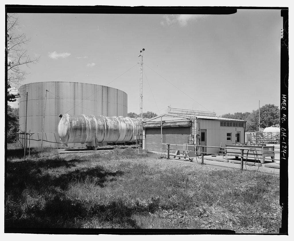
These data were sent to the adjacent observation room for transmission to the control room in Building The Scrubber/Silencer. The rocket exhaust was treated inside the scrubber/silencer, where the hot gas passed through a heavy spray of water. The scrubber/silencer consisted of several sections. The test engine was supported on a thrust stand over the inlet end. This conical section was attached to a horizontal tank measuring 25' in diameter and approximately 60' long. The scrubber was equipped with multiple water spray nozzles that cooled the exhaust stream, dissolved soluble matter, and captured solids. Exhaust gases produced by the rocket exited at velocities of feet per second and temperatures up to F.
The transition of the exhaust stream from a rocket nozzle measuring a few square inches in surface area to a horizontal scrubber/silencer tank with a cross section of more than 490 square feet slowed the exhaust to a velocity of approximately twenty-five feet per second. The cooled exhaust, clear of soluble compounds, entered an elbow-shaped transition to a vertical section of the scrubber/silencer. Exhaust emerged from this opening at a temperature below l 60 F, and at a velocity of around twenty feet per second. Additional water treatment equipment was located north of the scrubber/silencer. Water, condensed steam, and combustion by-products trapped by the scrubber drained into a detention tank with a capacity of gallons.
Wastewater remained in this tank until the end of the day's test program, when it was pumped into a neutralizing tank. Chemical technicians analyzed the wastewater and determined the quantity and type of additive needed to neutralize acidity or alkalinity. After treatment, the water was retested and then pumped to a holding tank. The treated water was then pumped to the municipal wastewater treatment plant, and solid wastes were sent to a stable landfill. 45 Solid wastes are essentially insoluble in water. For example, the waste generated by fluorine reactant treated with calcium hydroxide would be calcium fluoride, a compound with a solubility of parts per 100 parts by weight of water. The resulting compound is chemically the same as fluorite, a mineral found in nature. Building No.
205 - Propellant Transfer and Storage Area Building 205 was constructed ca. approximately north-northeast of the Rocket Engine Test Cell in Building The building is a lightly constructed shed that covers an area of about 1, 710 square feet. The original equipment has been removed from this building, and some cladding is missing from the east elevation, but the shell of the original building remains. 45A stable landfill is defined as one that presents no threat of polluting the environment, has no evidence of concentration gradient of pollutants between the landfill and the surrounding area, and that complies with legislative mandates.
The actual technical requirements and extensive material on developing a stable landfill are detailed in United States Environmental Protection Agency, Solid Waste Disposal-Facility Criteria - A Technical Manual EPA530-R-93-017 (Washington, U.S. Environmental Protection Agency, November Chapter 4, section D. ROCKET ENGINE TEST FACILITY HAER No. OH-124 Page 16 The Rocket Engine Test Facility did not use conventional electrically driven centrifugal pumps to deliver liquid oxygen to the test cell. When the Rocket Engine Test Facility complex was built from l commercially available mechanical pumps for handling cryogenic fluids were not ideally designed for forcing liquid oxygen at high flow rates into test engines.
To overcome the problems inherent in directly pumping liquid oxygen, the designers developed an indirect pumping system. The system used pressurized gaseous helium to transfer the pumping energy of electrically driven compressors to the liquid oxygen supply system. Building 205 housed the compressor and automated control system that pressurized helium gas to psi. This pressurized helium was then used to force liquid oxygen through the piping system. The helium that was pressurized by the compressor in Building 205 was then piped to the liquid oxygen tank in the oxidant pit at Building Control valves admitted pressurized helium into the liquid oxygen tank.
The pressurized helium pushed the liquid oxygen into the outlet pipe and out to the test rig at the rate necessary to obtain the engine's maximum thrust. 46 Building 206 -- Cryogenic Vaporizer Facility Building 206 was constructed in and has undergone little alteration. 47 This structure was part of the gas distribution system for the Rocket Engine Test Facility. Building 206 housed a liquid nitrogen vaporizer and a nitrogen gas compressor. It may have been designed to handle other gases, since the building was equipped with explosion-proof lighting and telephones. Inert, non-flammable nitrogen gas was used at the Rocket Engine Test Facility to power pneumatic actuators that opened and closed valves.
Electrically operated solenoid valves in tum controlled the pressurized nitrogen supply to the actuators. Hydraulic fluid pressurized the engines' fire control systems while the fire suppression system was pressurized with inert, non-flammable nitrogen gas. The most cost-effective method of transporting nitrogen, however, was to maintain it in liquid form. Large mobile Dewars could transport the nitrogen, and maintain it below its boiling point of-l C, with limited loss through evaporation. The liquid nitrogen had to be vaporized for use in the facility. A nitrogen vaporizer is basically a heat exchanger. 48 Liquid nitrogen was first fed through a pump/compressor, pressurized to psi. The highly pressurized liquid then flowed through a network of pipes to the vaporizer.
Fans pulled ambient air across the exterior surface of the pipes. The liquid nitrogen in the pipes warmed and boiled, forming high-pressure nitrogen gas. This gas was then piped throughout the Rocket Engine Test Facility for use. 46 Drawing No. CE-101632 - 17 Building 206 is sometimes referred to in NASA records as "Building in an effort to distinguish it from Building 206A, which is a different building that was constructed later. In this report, Building is always referred to as Building 48 John H. Perry ed., Chemical Engineers' Handbook (New York: McGraw-Hill Book Company, ROCKET ENGINE TEST FACILITY HAER No.
OH-124 Page 17 The use of pressurized air to actuate remote valves was common practice in the Textbooks of the period describe devices called "pneumatic diaphragm motors," which were used at the Rocket Engine Test Facility to open sliding stem control valves, dampers, rotary plug valves, and other remotely controlled devices, 49 The use of inert, compressed nitrogen to operate pneumatic actuators yielded an extra margin of safety in controlling reactive fuels and oxidants. Nitrogen also powered the ejectors that simulated the vacuum of space in Test Stand B, which was added to the facility in Building 100 - The Control Room Building 100 was built in during the original Rocket Engine Test Facility construction phase.
The northernmost wing of Building 100 housed the central control room where engineers ran and monitored rocket engine tests. Its location north of the actual test stand provided a safe location where engineers could run the tests. The transfer and pressurizing of the fuels and oxidizers used during the engine tests were also controlled from the control room. Equipment in this space also detected, monitored, and recorded engine performance during tests. A remote control facility enhanced the safety of testing new rocket engine designs using hazardous fuels, and test engineers could therefore collect and store data in an area that was unlikely to be damaged in case of catastrophic engine failure. The design of the control room followed standard practice of the time.
The main control and instrument consoles were centrally located and surrounded by model or control boards that showed the operating status of the major valves, pumps, motors, and actuators. The control console and model boards were schematic representations of the system, with colored lines that represented the pipes carrying reactants to the engine being evaluated. 50 Test engine operations were complex and short, rarely lasting more than a few minutes. During that brief time, transient events could occur that were significant to longer-te1m perfo1mance, but human reaction time was insufficient for manual operation of a test. In addition, real-time direct observations by engineers did not yield much useful data.
Consequently, the operation, sensing, and recording of engine tests were mostly done using electro-mechanical devices or computers. In the late programmable controllers were developed. With the development of the personal computer, these devices were re-designated as programmable logic controllers, or At the Rocket Engine Test Facility, programmable logic controllers made by the Modicon Corporation replaced the earlier electro-mechanical devices used in the control system. A programmer calibrated the PLC to operate the valves and actuators controlling the fuel, oxidant, and ignition sequence according to a predetermined time schedule. The engine test runs were nominally controlled by the but they could be manually overridden by a "panic button" located on the main control panel.
49 Perry, so Drawing No. -- . ROCKET ENGINE TEST FACILITY HAER No. OH-124 Page 18 Originally, the performance data of a run were recorded on magnetic tape, thermal paper linear recorders, multicolor pen recorders, or "Visicorders," devices manufactured by Honeywell that recorded several events simultaneously. In the personnel at the Rocket Engine Test Facility reduced raw data using TRADAR or CADDE programs that were written by Lewis Research Center personnel specifically for rocket engine testing. These data were then fed by direct digital data link to the Research Analysis Center (RAC) in Building where IBM TSS and Cray 1-S computers, as well as DEC VAX clusters, further processed data before transmitting it to the control room for analysis.
51 This system provided on-line data processing facilities to the control room, hard copy terminals, and monitors located in the rocket operations building control room. The control room has undergone several re-configurations since Changing technology and the addition of a high-altitude rocket test stand and a turbo pump test stand required the addition of new control and recording equipment. In Test Stand C was added to Building This stand was used to test seal materials and designs for liquid oxygen pumps and other components. The controls for Test Stand C were located in instrument racks on the southeast side of the control room.
Observation Blockhouse The observation blockhouse was also built during the original Rocket Engine Test Facility construction phase of During the early years of operation at the Rocket Engine Test Facility, technicians and engineers relied on direct human observation of engine firings to supplement instrument readings. Some of these observations were made by engineers and technicians stationed in a small blockhouse located approximately north of the test stands in Building 52 The blockhouse protected these observers from flying debris in case of catastrophic engine failure. The blockhouse was equipped with an intercom system, emergency communications, and a telephone system to allow two-way contact between observers and test engineers.
Positioned below the observation window was a "panic button" similar to the one in the Building l 00 control room. The observer could activate this button to initiate an automatic test shutdown under programmable logic control, in case of an emergency. 53 As sensors, instrumentation, and computerized data reduction became more sophisticated, the infonnation that could be provided by observers in a protected area was less significant and the blockhouse fell into increasing disuse. In the staff installed a closed-circuit television system with a camera on top of the 51 Email letter from Kevin P. Coleman, Records and Electronic Forms Manager, History Office Liaison, NASA, John H. Glenn Research Center at Lewis Field, Cleveland, Ohio. 52 Drawing - 53 See HAER No.
OH-124-D - GRC Building 100 - Rocket Operations Building. ROCKET ENGINE TEST FACILITY HAER No. OH-124 Page 19 blockhouse. 54 The test cell in Building 202 and the surrounding area were also equipped with additional lighting, which enabled technicians and engineers in the Building 100 control room to observe tests on closed-circuit television. This further enhanced safety and reduced the need for observers stationed in the blockhouse. Conclusion: The Rocket Engine Test Facility was an outstanding example of a research and development operation that made major contributions to several space programs. It was instrumental in developing liquid-hydrogen-fueled rocket engines.
Its staff, engineers, and technicians exhibited creativity and ingenuity in developing effective solutions to complex engineering problems. The facility was designed with sufficient foresight and flexibility to allow the expansion and use of new technologies that were developed during its working period. Researchers at NASA's Glenn Research Center continue to do outstanding work in rocket research, and their recent efforts have focused on rocket-based combined-cycle engines. These engines combine both rocket and air- breathing propulsion systems to reduce the cost of on-board oxygen by using atmospheric air for a portion of the burn. 55 54 Interview with George Repas I 55 Jeff Hass, "Ground Testing," Aerospace America (December 77. ROCKET ENGINE TEST FACILITY HAER No.
OH-124 Page 20 Sources of Information/Bibliography A. Engineering Drawings: NASA Lewis Research Center - Cleveland, Ohio Rocket Engine Test Facility Observation Post Drawing No. CF - National Advisory Committee for Aeronautics -- Lewis Flight Propulsion Laboratory - Cleveland, Ohio Rocket Engine Research Facility-- Test Cell Building Foundation Plan Drawing No. CE-101310-6/29/55 National Advisory Committee for Aeronautics - Lewis Flight Propulsion Laboratory -- Cleveland, Ohio Rocket Engine Research Facility Exhaust Duct and Detention Tank - Demister Support Details General Plan and Miscellaneous Details Drawing No.
CE-101261 National Advisory Committee for Aeronautics - Lewis Flight Propulsion Laboratory - Cleveland, Ohio Rocket Engine Research Facility -- Exhaust Duct and Detention Tank Exhaust Duct Elevations and Sections Drawing No. CE-101263 --- National Advisory Committee for Aeronautics -- Lewis Flight Propulsion Laboratory - Cleveland, Ohio Rocket Engine Research Facility -- Exhaust Duct and Detention Tank Exhaust Duct Wash Down Spray System Drawing No. CE-101276---7/18/55 NASA Lewis Research Center- Cleveland, Ohio Rocket Engine Test Facility Oxidant Tank Details Drawing No. National Advisory Committee for Aeronautics - Lewis Flight Propulsion Laboratory -- Cleveland, Ohio Rocket Engine Research Facility-- Fuel Tank General Assembly Drawing No. CE-101634-- ROCKET ENGINE TEST FACILITY HAER No.
OH-124 Page 21 NASA Lewis Research Center - Cleveland, Ohio High Pressure Propellant System for Rocket Engine Test Facility Oxygen System Schematic Diagram Drawing No. - NASA Lewis Research Center - Cleveland, Ohio Facility Plan and Equipment Layout RETF Area Master Plan S-40-Drawing No. CF NASA Lewis Research Center-Cleveland, Ohio Rocket Engine Test Facility- Building No. 202 - Pilot Plan Equipment Location Drawing No. National Aeronautics and Space Administration - Lewis Research Center - Cleveland, Ohio Gaseous Nitrogen System-Turbo Machinery Test Facility Building 202 PSIG Gaseous Nitrogen Supply Test Stand C Drawing CE-183172 - NASA Lewis Research Center - Cleveland, Ohio Rocket Engine Test Facility-Gaseous Nitrogen System South 40- Building No.
202 psig Gaseous Nitrogen Supply System Schematic Drawing No. - NASA Lewis Research Center- Cleveland, Ohio Rocket Engine Test Facility- Gaseous Nitrogen System South 40 - Building No. 202 psig Gaseous Nitrogen Supply System Schematic Drawing No. - NASA Lewis Research Center - Cleveland, Ohio Rocket Engine Test Facility for Altitude Testing Piping Section Drawing No. - B. Interviews: Repas, George, Hardware Design Engineer Interview by the author, 28 May Cleveland, Video recording, Hardlines Design Company, Columbus, Ohio ROCKET ENGINE TEST FACILITY HAER No.
OH-124 Page 22 Repas, George, Hardware Design Engineer Interview by the author, 24 October West Suffield, Connecticut, Telephone interview, Hardlines Design Company, Columbus, Ohio Repas, George, Hardware Design Engineer Interview by the author, 15 November West Suffield, Connecticut, Telephone interview, Hardlines Design Company, Columbus, Ohio C. Letters: Diehl. Larry A. Cleveland, 5300/Chief, Space Propulsion Technology Division, Cleveland, to Acting Director of Technical Services. January 31, Archives: NASA Glenn Research Center, Cleveland, Ohio. D. Slide Presentation: Aerospace Technology Facilities Division. REIF CoF Status. Record of overhead slides prepared for meeting. (Cleveland, LeRC) Undated but probably Archives: NASA-Glenn Research Center, Cleveland, Ohio. E.
Websites: HABS-HAER website http://memory.loc.gov/ ammem/hhquery.html NASA website http://www.ssc.nasa.gov National Park Service website www.cr.nps.gov/history/online books/butkowsky4 F. Secondary
 Block
Block