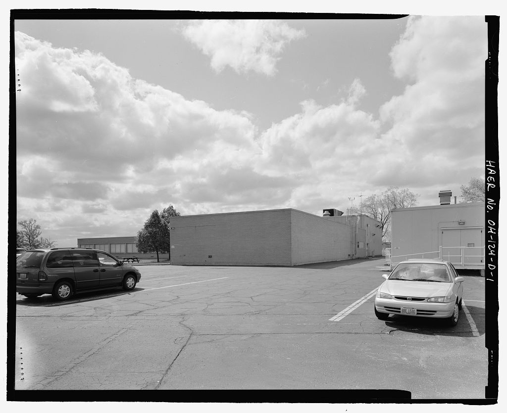
This documentation was initiated on May 15, in accordance with a Memorandum of Agreement among the Federal Aviation Administration, NASA, The Ohio State Historic Preservation Officer, and the Advisory Council on Historic Preservation. The City of Cleveland plans to expand the Cleveland Hopkins International Airport. The NASA Glenn Research Center Rocket Engine Test Facility, located adjacent to the airport, must be removed before this expansion can be realized. To mitigate the removal of this registered National Historic Landmark, the National Park Service has stipulated that the Rocket Engine Test Facility be documented to Level I standards of the Historic American Engineering Record (HAER). This project was initiated to fulfill that requirement. Historians: Robert C.
Stewart Historical Technologies, West Suffield, Connecticut Dr. Virginia P. Dawson History Enterprises, Cleveland, Ohio Introduction: Building 202 is located on land that was formerly part of the Cleveland Municipal Airport. NASA currently owns this property. From the airport expanded to cover more than acres. During this period the airport was home to the National Air Races, and the western portion of the airport served as a parking area during these events. In the National Advisory Committee on Aeronautics (NACA) decided to build its Aircraft Engine Research Laboratory on 200 acres of the airport site. This location included the National Air Races parking lots and an adjacent strip of land that belonged to the Cleveland Metropolitan Park.
In April the Aircraft Engine Research Laboratory was renamed the Flight Propulsion Research Laboratory to reflect its role in propulsion research. The name changed again in to the Lewis Flight Propulsion Laboratory, in honor of George William Lewis.2 In the name was modified once again, to the Lewis Research Center. This name change reflected the facility's role in the new NASA, which had developed around a core ofNACA facilities.
Lewis Research Center continued its role as a NASA research facility throughout the and 2George Lewis served as Director of Aeronautical Research for the National Advisory Committee for Aeronautics (NACA) from Under his leadership, NACA's Langley Research Laboratory established its reputation for outstanding contributions to aeronautical knowledge, which included both basic engineering research and testing. Lewis was responsible for obtaining funding for NACA's many unique test facilities. During World War II he oversaw the building of two additional national aeronautical research laboratories. The Lewis Flight Propulsion Laboratory was named after Lewis because of his important role in NACA. ROCKET ENGINE TEST FACILITY,
No. 202 (Rocket Propulsion Test Facility- Rocket Test Cell Building HAER No. OH-124-A Page 3 and in March the center was officially renamed the NASA John H. Glenn Research Center at Lewis Field. Today, the Glenn Research Center at Lewis Field occupies more than 350 acres west of Cleveland Hopkins International Airport.3 A map in the graphics section of this report shows the location of this research facility. A request authorizing construction of a test facility for evaluating high-energy propellants and rocket engines was approved in As built, the facility consisted of a test cell and ancillary buildings dedicated to the testing of full-scale rocket engines.
The complex was located on ten aces of a 40-acre tract known locally as the "South 40" and situated at the south end of NASA's Glenn Research Center. The new Rocket Engine Test Facility was designed to permit up to three minutes of rocket engine operation at a thrust of eighty-nine kilonewtons. Upon its completion in the fall this facility was the largest high-energy rocket engine test facility in the United States. Built at a cost of million, the complex originally encompassed two major components: a control center housed in Building and a test cell at Building Other components included an observation blockhouse constructed as part of the original construction phase, and Buildings 205 and built in the to accommodate liquid fuel and oxidizer vaporization facilities.
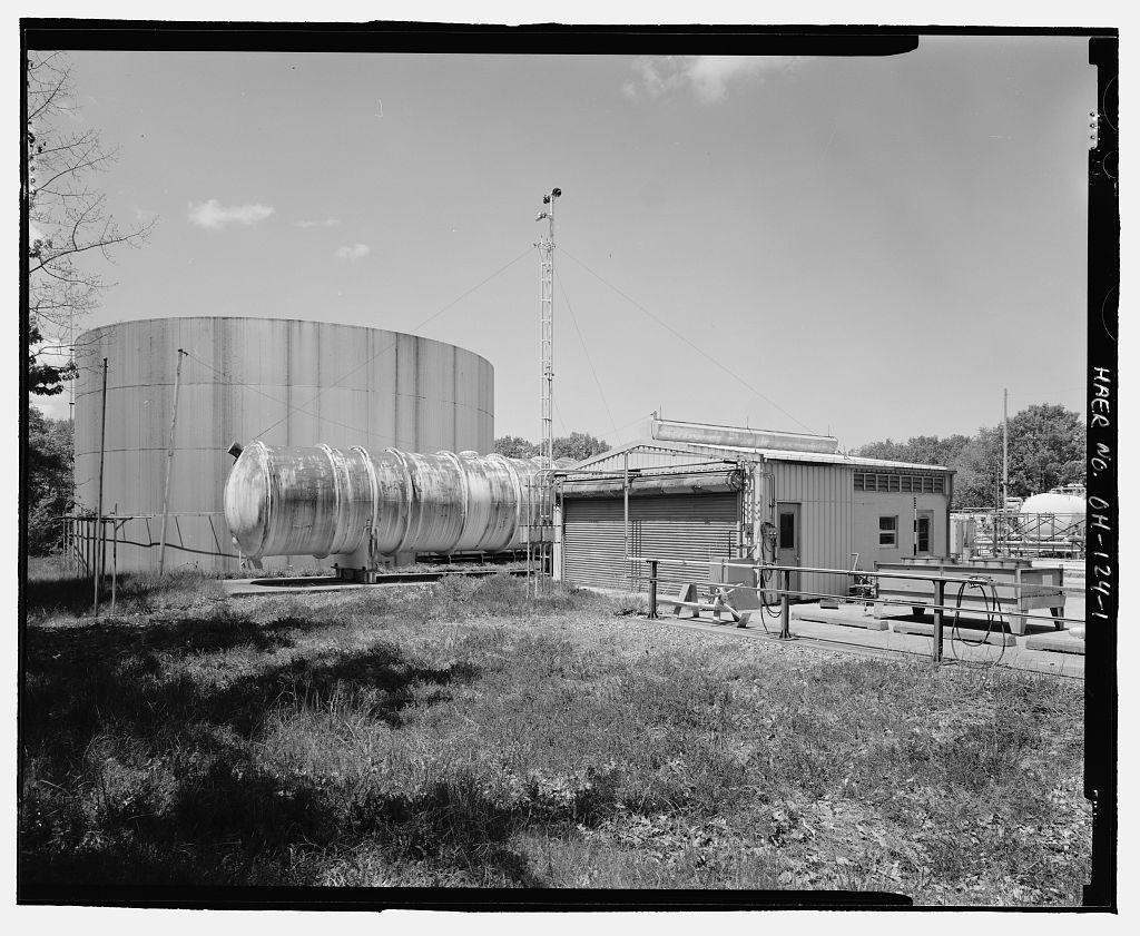
Building 202 included a test cell, a propellant supply system, and a distinctive system for scrubbing exhaust gases to remove waste products generated during combustion. The scrubber also silenced the noise of rocket firing. There was a small shop adjacent to the test cell where personnel assembled engines and installed instruments to measure test data. Also adjacent to the test cell was a tank farm of high-pressure helium bottles. Storage areas for some fuels, liquid oxygen, and water were located on the hillside east of Building From this elevated storage location, hydrocarbon fuels, ammonia, and hydrazine were transported by gravity to the test cell below. Propellant pressure tanks were filled with fluorine or liquid hydrogen transported to the facility on trailers.
Water for the scrubber was supplied using a gravity-fed system from a tank with a capacity of gallons. It must be emphasized that the Rocket Engine Test Facility was classified as a research facility. As such, the staff focused on a mission to test new designs and concepts, analyze successes and failures, re-design, and re-evaluate. The environment fostered creative and innovative solutions in a field of study that was new and in which there were many unknown factors. While major aerospace companies were conducting corporate research in rocket engine development, the Rocket Engine Test Facility was able to evaluate novel concepts and transfer viable ones to other research facilities for scale-up and possible production.
The type of research that was completed produced data cost-effectively by testing model and sub-scale engines. Sub-scale testing also produced useful design data with minimal use of expensive fuels and oxidizers. Typically these test engines had chambers with throats, or 10" chambers with 3 National Aeronautics and Space Administration, "Lands of the Lewis Research Center" (Cleveland: National Aeronautics and Space Administration, ROCKET ENGINE TEST FACILITY, GRC BUILDING No. 202 (Rocket Propulsion Test Facility- Rocket Test Cell Building HAER No. OH-124-A Page4 throats. Using high-pressure reactant feeds, an engine with a throat could produce thrusts of 75 kilonewtons pounds).
The complex had the high-pressure capabilities and facilities for testing a comprehensive variety of rocket fuels and oxidants. An addition that was constructed in and which was known as Test Stand B, equipped Building 202 for the testing of large area ratio rocket nozzles under conditions that simulated those in space. 4 Building 202 played a pivotal role in the development of hydrogen rocket fuel technologies. Research conducted by NASA personnel at this test facility contributed to the successful development of the Centaur rocket and the upper stages of the Saturn V rocket.
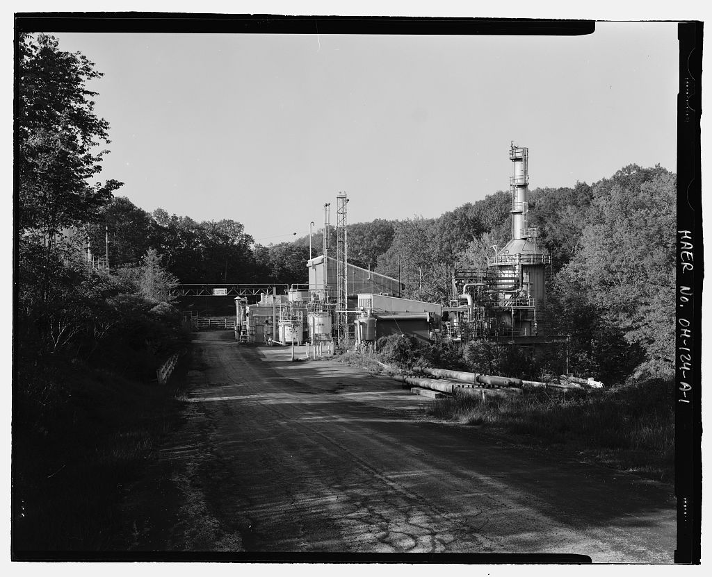
The research completed at Building 202 was therefore central to the success of the Apollo moon exploration program in the late and Site Description: The Rocket Engine Test Facility complex is located on a ten-acre site within a forty-acre area at the southern end of NASA's Glenn Research Center. This location is locally known as the "South Building the Rocket Engine Test Facility Rocket Test Cell Building, is located on the side of a small, steep gorge. The gorge drains an arm of Abram Creek, which is a tributary of the Rocky River. The east side of the gorge was contoured during construction to create a uniform slope, and two service roads were provided for the facility. Both service roads paralleled the hillside contours and permitted relatively level access up the steep hillside.
The lower service road led to the test cell, while the upper road serviced Building Building and the water reservoir. The general Rocket Engine Test Facility site is accessible from the Lower South Road at NASA Glenn Research Center. South Road begins at the intersection of Walcott Road and Cedar Point Road in the Glenn Research Center complex at Lewis Field. The elevation of Building 202 at the test cell floor is above sea level. The surface of Abram Creek is approximately 50' below the test cell floor. Several ancillary structures stand in the immediate vicinity of Building Two of these are Building the South Area Propellant Transfer and Storage Area, and Building the Cryogenic Vaporizer Facility.
Other support structures in the immediate area include the 500,000-gallon water storage reservoir, which was built on the hillside at an elevation of above sea level. The hillside site and the placement of the water storage tank at an elevation above Building 202 allowed water to be gravity-fed to the scrubber/silencer. The reservoir water was used to scrub exhaust gases produced by the rocket engines being tested. The final support facility is a small observation blockhouse positioned approximately north of the test cell. All of these support structures are functional industrial buildings devoid of architectural or aesthetic features. They are representative examples of form dictated by function.
4 Harry Butowsky, "Rocket Engine Test Facility, National Register of Historic Places Nomination" (Washington, United States Department of the Interior, National Park Service, ROCKET ENGINE TEST FACILITY, GRC BUILDING No. 202 (Rocket Propulsion Test Facility- Rocket Test Cell Building HAER No. OH-124-A Page 5 Description of Building General: Building 202 was built on an L-shaped plan. The longer leg was constructed using I-beam uprights and lighter structural steel forms, and the building exterior was sheathed with vertically corrugated, insulated metal wall panels. The facility contained an observation room, an office, a tool crib, and a locker room with toilets and a shower. A utility bay housed a boiler and an electrical distribution cabinet.
A small substation room housed a transformer and switchgear. The facility's welding booth occupied the southwest comer of the building. The central area of this wing provided space where technicians could service engines and prepare them for a test. The southern part of the building that fronts on Lower South Road had an overhead garage door that opened into the central service area. Two overhead monorail cranes lifted engines from trucks or trailers and carried them to the service area or welding booth. A stairway led to a small basement below the service area, where a compressor tank and heat exchanger were stored. The base of the L-shaped plan housed the fuel and oxidant pits, test cell, scrubber/silencer, valve house, and pump house.
Wastewater treatment facilities were located north of the scrubber/silencer. The Fuel and Oxidant Pits: The fuel pit, oxidant pit, and observation room were constructed of reinforced concrete. The floor level of both pits was 26' below the test cell floor. The fuel and oxidant pits were separated from the test cell and observation room by a 2'-thick reinforced concrete wall. 5 This heavy construction could withstand an explosion or fire in the test cell. was transferred from a tanker to a cylindrical tank vessel suspended from a frame in the fuel pit. The frame was equipped with a Baldwin load cell that transmitted analog data regarding the weight of the fuel and vessel to the control room. 6 The oxidant pit was similarly equipped with liquid oxygen tanks.
An outer jacket containing liquid nitrogen enveloped the oxygen tanks. 7 Liquid oxygen was transferred from a mobile tanker-trailer into a double-walled, vacuum-insulated tank called a "Dewar," which was located on the hillside west of Building 8 Oxygen flowed to the tanks in the oxidizer pit through a pipe that was jacketed with a liquid nitrogen bath. The liquid 5 Drawing CE-101310 Test Cell Building Foundation Plan. 6 Drawing CE-101634 Fuel Tank - General Assembly. 7 Liquid nitrogen boils at -l C, while liquid oxygen boils at - l 83 C. As a result, the liquid nitrogen maintained the liquid oxygen below its boiling point and prevented significant evaporative loss. It also guaranteed greater accuracy in determining actual oxidant usage.
8 Sir James Dewar invented the Dewar flask in It insulated against the transfer of heat by conduction, convection, or radiation. It was commercialized in as the "Thermos" flask. ROCKET ENGINE TEST FACILITY, GRC BUILDING No. 202 (Rocket Propulsion Test Facility- Rocket Test Cell Building HAER No. OH-124-A Page 6 oxygen was forced from the tanks and into the test engine by pressurized helium gas, which displaced the oxygen. The fuel and oxidant pits were both equipped with sprinkler systems for fire suppression. During experiments with fluorine, the liquid nitrogen bath served to liquefy any vaporized fluorine that leaked from the tank. This was a safety feature that minimized the possibility of atmospheric fluorine release.
The termination or observation room was designed to protect test observers and the electronic equipment used to transmit data to the control room in Building Using a periscope-like window and mirror system, engineers in the observation room directly observed rocket engine tests from a safe location. The test engineer in the observation room could also press an "abort" button that would immediately shut down a test through a programmable logic controller. The Test Cell: 9 The vertical test stand located at the center of the test cell was built to accommodate rocket engines firing with a maximum thrust of pounds. This limit was imposed by the weight of mountings, plumbing, controls, and instrumentation.
The facility's scrubber/silencer and foundations were designed, however, to handle engines exerting up to pounds of thrust. The supporting frame for the engine was instrumented with strain gauges, pressure sensors, load cells, and thermocouples that measured the engine thrust and other data. These data were sent to the adjacent observation room for relay to the control room. The cell measured wide and deep, and enclosed a usable floor area of square feet. The shed roof of the test cell was 25' high on the west side and 35' high to the east. The test cell enclosure consisted primarily of upright steel I-beams, which were the major structural members, while lighter steel channel and angle beams fastened between the I-beams produced a modular framed structure.
The walls and roof of the structural frame were sheathed in corrugated cement asbestos sheets, also known as "Transite" or "Carrystone." These sheets measured thick and were lightly fastened to the framework. If an explosion occurred during a test, the sudden increase in pressure inside the test cell blew these sheets free of the frame and relieved the internal pressure. The sheathing was then easily replaced. In later years, lightweight, translucent fiberglass/resin sheets replaced the cement asbestos panels. These provide the same benefits as the asbestos cement, but they also allowed more light into the test cell. The west facade of the test cell had a double sliding door that, when opened, exposed approximately one-third of the cell's width to the outside.
A window centered over the sliding door measured 7' high and wide, and consisted of thirty-five lights, which were arranged in seven horizontal and five vertical rows. When opened, a double sliding door on the north 9The descriptive material on the test cell and its operation was obtained during a videotaped tour of the facility led by George Repas, who was employed as a hardware design engineer at the Rocket Engine Test Facility during most of the years that the facility was in operation. ROCKET ENGINE TEST FACILITY, GRC BUILDING No. 202 (Rocket Propulsion Test Facility- Rocket Test Cell Building HAER No. OH-124-A Page 7 side of the test cell exposed about one-half of the cell interior to the outside. The fuel and oxidant pits partly conceal the lower east facade of the test cell.
A window extended across the facade above the roofline of the fuel and oxidant pits. This window was a steel-frame industrial type unit that measured 4' 6" high and 27' wide. This window had forty-two lights, mounted three high and fourteen wide. An additional louvered vent with a windscreen was placed at the peak of the shed roof and covered the full width of the test cell. This louvered vent was approximately 3' high. The roof slanted upwards to the east to allow loose hydrogen gas to escape. Two gas unit heaters maintained a comfortable working temperature inside the test cell during set-up operations. 10 Pipes supplied with nozzles were positioned along the inner perimeter of the test cell near the roofline, and could spray water into the cell to suppress fire.
Additional pipes and nozzles could flood the test cell with carbon dioxide to control fires. A centrally located opening led from the test cell into the scrubber/silencer below. This oversized circular opening was covered by as many as twelve wedge-shaped steel plates that could be adjusted to change the diameter of the opening to accommodate various engine support systems. The transitional passage into the scrubber/silencer was a conical piece approximately high. The top of the cone was a heavy steel flange with a circular opening that measured 4' in diameter. At the bottom of the cone, where the piece joined the horizontal tank, the aperture measured 12' in diameter. 11 Several burners near the rocket exhaust ignited any hydrogen or other fuel that had not burned inside the engine.
These burners prevented unburned fuel from building to explosive levels inside the scrubber. The test stand or rig that supported the engine was mounted over the flange at the top of the cone so that engine exhaust vented directly into the scrubber/silencer. The Scrubber/Silencer: The remammg section of the base of the building's L-shaped plan contained the scrubber/silencer that treated exhaust by directing the hot gas through a heavy spray of water. The water for scrubbing exhaust was supplied by a tank on the hillside at an elevation of above sea level, approximately 50' above the inlet to the scrubber/silencer. 12 This tank had a capacity of gallons. The scrubber/silencer consisted of several sections. The test engine was supported on a thrust stand over the inlet end.
This conical section was attached to a horizontal tank that measured 25' in diameter and approximately 60' long. The conical section was equipped with four water 10 Drawing Plot Plan Equipment Location. 11 Drawing - Exhaust Duct - Inlet Cone and Details. 12 Ibid. ROCKET ENGINE TEST FACILITY, GRC BUILDING No. 202 (Rocket Propulsion Test Facility- Rocket Test Cell Building HAER No. OH-124-A Page 8 ) spray nozzles for cooling. A concave end cap closed the end of the tank closest to the thrust stand, and a manifold fitted with spray nozzles was mounted on this end cap. Additional manifolds with spray nozzles cooled and protected three sides of the "firing duct" immediately below the inlet cone.
While the spray from these nozzles somewhat cooled the exhaust, their chief function was to protect the scrubber/silencer components nearest the rocket exhaust from thermal damage. 13 The distal end of the tank section housed five pipe manifolds that supported additional water spray nozzles for thermal diffusion. 14 The silencer/scrubber configuration then narrowed through a 7'-long transitional cone to a diameter of The exhaust path then entered a ninety-degree elbow before passing through the vertical stack, which measured 20' in diameter and rose to 35' 9" above the test cell floor. 15 Two spray manifolds with nozzles were located inside the stack just above the elbow and provided additional cooling and cleaning.
Once the exhaust passed through this transition to the scrubber/silencer's vertical stack, the stream had cooled and was clear of most water-soluble compounds. Near the top of the stack, several de-mister units removed small water droplets from the exhaust stream. 16 During a test run, the reservoir supplied water under gravity flow to the nozzles at a rate as high as gallons per minute. This water flow was controlled by a bank of valves mounted on the south side of the scrubber/silencer's horizontal portion. Exhaust gases exited the rocket engines at velocities of to per second and at temperatures of F. The water spray dissolved soluble matter, captured solids, and cooled exhaust gases.
The passage of the exhaust stream from a rocket nozzle no larger than a few square inches to a horizontal scrubber/silencer tank with a cross section of more than 490 square feet slowed the exhaust to a velocity of approximately 25' per second. By the time the exhaust stream emerged from the stack at about 20' per second, the temperature had decreased to less than l 60 F. Additional equipment for water treatment was located north of the scrubber/silencer. Water, condensed steam, and combustion by-products trapped by the scrubber drained into a gallon detention tank. This tank was located at the lowest point in the complex, adjacent to a fork of Abram Creek. This tank held wastewater until the completion of the daily test program, when the water was pumped to a neutralizing tank.
The neutralizing tank consisted of an oil separation chamber and a sand filter. Chemical technicians analyzed the wastewater and determined the quantity and type of additive needed to neutralize acidity or alkalinity and establish a pH value 17 that met municipal wastewater standards. Technicians added chemicals 13 Drawing Exhaust Duct Wash Down Spray System. 14 Drawing - Exhaust Duct Elevations and Sections. 15 Ibid. 16 Drawing - Demister Support Details. 17 The pH is a measure of acidity or alkalinity. Values below 7.0 indicate increasing acidity while values between 7 .0 and indicate increasing alkalinity. ROCKET ENGINE TEST FACILITY, GRC BUILDING No. 202 (Rocket Propulsion Test Facility- Rocket Test Cell Building HAER No.
OH-124-A Page 9 to the neutralizing tank through a "lime pump house," and the additives reacted with the combustion by-products in the wastewater. Some fuel/oxidizer combinations produced highly corrosive acid by-products, and the use of fluorine created hydrofluoric acid as a by-product. Reaction of water containing hydrofluoric acid with a calcium compound in the neutralizing tank produced a stable, solid precipitate of calcium fluoride. After treatment, technicians then retested the water before pumping it into a holding tank known as the "collector basin," or "swimming pool," as it was commonly called. This treated water was then pumped to a municipal wastewater treatment plant, and the solid wastes were sent to a stable landfill.
The 500,000-gallon reservoir also supplied water to cool the rocket engine nozzle during active testing. This cooling water was pumped using a or a 1,450-gallon-per-minute pump. In addition, the reservoir supplied the line of fire suppression spray nozzles positioned around three sides of the test cell approximately 24' above the floor. The west side of the cell was not equipped with nozzles. Operations: Standard operating procedures were followed when preparing an engine test. was pumped from a mobile tanker-trailer into cylindrical tanks in the fuel pit. These tanks were mounted in a suspension framework equipped with load cells that measured the weight of both empty and full tanks.
The load cells could determine the weight of the tank while fuel was being drawn, and by comparing the weight of a full tank with the tank's weight after completing a test, test engineers could accurately calculate the weight of fuel burned during the procedure. Rocket Engine Test Facility personnel could determine the rate of fuel use by plotting tank weight against run time. Variable position hydraulic valves controlled the pressure of inert helium gas flowing into the fuel tanks. This gas pressure forced fuel from the tanks and into the rocket engine under test. Liquid oxygen was transferred from a mobile tanker-trailer, also known as a mobile liquid Dewar, into a double-walled, vacuum-insulated tank, or stationary Dewar.
The stationary Dewar was located on the hillside west of Building Oxygen flowed through a pipe that was jacketed in a liquid nitrogen bath, and ran to the tanks in the oxidizer pit. The tanks in the oxidizer pit were encased in outer tanks that also contained a liquid nitrogen bath. These liquid nitrogen baths maintained the oxygen in a liquid state. The liquid oxygen was then forced from the tanks and into the test engine by displacement from helium gas under pressure. The system of using gas pressure to move reactants to the engine eliminated the need for expensive turbo pumps. The rocket engine under test was then cooled by water supplied from the reservoir and pumped using a or a 1,450-gallon-per-minute pump.
Working pressure ratings for the primary liquid hydrogen, liquid oxygen, cooling water, and hydrocarbon propellant systems was pounds per square inch (psi). Storage pressures were psi for gaseous hydrogen, psi for gaseous helium, and psi for gaseous nitrogen. The site provided bulk storage for gallons of liquid nitrogen, gallons of ROCKET ENGINE TEST FACILITY, GRC BUILDING No. 202 (Rocket Propulsion Test Facility - Rocket Test Cell Building HAER No. OH-124-A Page 10 liquid oxygen, and gallons of liquid hydrogen. Gas pumping equipment could provide hydrogen at psi, helium at psi, and nitrogen at psi to the gas bottle farms.
History: While exotic propellants offered higher specific impulse, from a practical standpoint, researchers could develop many solutions to rocket engineering design problems by using common fuels. Technicians and engineers gained valuable experience and knowledge by testing and operating prototype rocket engines, regardless of which reactants were used. Consequently, the first experimental engines tested at the Rocket Engine Test Facility were gasoline-fueled and tested on a vertical test stand at the center of the test cell. This stand was capable of supporting engines that exerted up to pounds of thrust. Liquid oxygen was used as the oxidant. Building 202 was originally designed to handle these volatile reactants.
The Rocket Engine Test Facility was planned and constructed as a rocket engine research facility. As part of its mission as a nationwide laboratory focused on aircraft engines, Lewis Flight Propulsion Laboratory had begun rocket propulsion research as early as There was strong interest in rocketry for U.S. military applications during the early Cold War years due to the success of the German V-2 rocket during World War IL Rocket propulsion research completed at Lewis Laboratory in the late was circulated to the Navy Bureau of Aeronautics, Air Materiel Command, and other U.S. military organizations. 18 When the initial request for construction of the Rocket Engine Test Facility was made in much of the rocket research at Lewis Laboratory was related to military applications.
This was still true in when construction began on the Rocket Engine Test Facility. 19 It was only after the successful launch of Sputnik by the Soviet Union in that the potential of the Rocket Engine Test Facility research for space travel was more strongly emphasized. 20 Building 202 was constructed from as part of the original Rocket Engine Test Facility construction phase. Construction drawings of the buildings date from The original building consisted of a test cell, shop area, the observation room, oxygen and fuel pits, a scrubber/silencer, and associated pump and wastewater handling facilities.
By the late research engineers and scientists working at the Lewis Research Center were persuaded that hydrogen was the optimum fuel for upper-stage rockets, although whether liquid oxygen or fluorine was the ideal oxidizer was still being debated. However, many practical solutions for engineering problems had to be resolved before the theoretical advantages of hydrogen/oxygen propulsion could be achieved. Hydrogen is a powerful fuel that must be handled carefully to 18 Virginia P. Dawson, "History of the Rocket Engine Test Facility at NASA-Glenn Research Center" (draft). On file at Hardlines Design Company, Columbus, Ohio, (February 19, 19 Ibid., 12, 25. 20 Ibid., ROCKET ENGINE TEST FACILITY, GRC BUILDING No. 202 (Rocket Propulsion Test Facility - Rocket Test Cell Building HAER No.
OH-124-A Page I I mm1m1ze the danger of an explosion. In addition, large quantities of hydrogen were not available during the early years of the rocket research program. The Rocket Engine Test Facility was originally designed to handle engines using liquid oxygen (LOX) and rocket propellant which was a refined grade of kerosene. NASA researchers tested early experimental engines on the facility's vertical test stand (Stand A), which could support engines that exerted pounds of thrust. Liquid oxygen was used as the oxidant.
However, records indicate that engines using a hydrogen-fluorine combination were tested at the Rocket Engine Test Facility from including a test of a regeneratively-cooled hydrogen-fluorine engine with a 480-pound thrust, the highest thrust attained by any chemical up to that time. roe k et engme 21 By the reactants such as nitrogen tetroxide, un-symmetrical dimethyl hydrazine, and fluorine were increasingly used in tests at the Rocket Engine Test Facility, although all fluorine testing ended by because it was considered impractical as an oxidizer. 22 Use of these chemicals at the Rocket Engine Test Facility resulted in the extension of the scrubber exhaust stack to guarantee thorough removal of toxic exhaust products.
A transitional cone was mounted on top of the stack, thereby reducing the opening to 6' in diameter and extending the stack to a total height of At the top of the scrubber stack a flare ring ignited any residual hydrogen. In its original form and as modified, the scrubber/silencer was a well-engineered solution to a waste treatment problem. The scrubber system was instrumental to the maintenance of high environmental quality in the vicinity of the Rocket Engine Test Facility. When the Rocket Engine Test Facility closed in there were nine propellant systems consisting of Dewars and tanks with working pressures of to psi connected to the test stands with stainless steel, vacuum, or liquid-nitrogen-jacketed pipelines.
The use of gas pressure to force the reactants from the tanks and into the test engines eliminated the need for high-pressure rocket turbo machinery and pumps. Hydraulic variable position valves controlled both the pressurized gas flows to the run tanks and the reactant gas flows to the rocket engine. The system was flexible and allowed multiple configurations that could support any particular test program. In Building 202 was modified to add capabilities for evaluating rocket nozzles with ratios of up to on small, low-thrust engines. The new test stand, called Test Stand B, simulated the vacuum of space through a large vacuum tank that housed the engine during active testing.
Engines were mounted horizontally in this test stand, while the engine exhaust was directed through a water-cooled diffuser and inter-cooler, and into the existing scrubber/silencer. Two gas ejectors powered by the facility's nitrogen supplies created the 21 !hid., 22According to George Repas; cited in NASA-Glenn Research Center, "Comments on Rocket Engine Test Facility Historic American Engineering Record Documentation" (January 24, 5. ROCKET ENGINE TEST FACILITY, GRC BUILDING No. 202 (Rocket Propulsion Test Facility- Rocket Test Cell Building HAER No. OH-124-A Page 12 vacuum. 23 Normally this type of ejector was steam-powered, but the availability of an existing on-site high-pressure nitrogen supply made the use of this gas cost-effective.
In Test Stand C was added to Building This stand was used for testing seal materials and designs for liquid oxygen pumps and other components. The initial test program tested seals on a turbo pump rig. Some of the controls for Stand C were located in a rack on the southeast side of the control room. There was also a complete gauge board inside the test cell. 24 The last tests at the Rocket Engine Test Facility occurred in Since that time, Building 202 has been vacant. Building along with the entire Rocket Engine Test Facility at the Abram Creek site, is scheduled for demolition to make way for expansion of Cleveland Hopkins International Airport.
Conclusion: The Rocket Engine Test Facility contributed to NASA's Apollo Program by extensive testing of liquid hydrogen/liquid oxygen propellants. These propellants were used in the upper stages of the giant Saturn rocket, the rocket propulsion system responsible for transporting human beings to the moon. NASA personnel conducted research using the test stands in Building 202 that was critical to the development of liquid hydrogen as a reliable and safe rocket fuel. The design of the Rocket Engine Test Facility was a successful, functional layout for this research facility, and NASA scientists achieved major progress in the isolation and resolution of engine design problems.
The staff at the Rocket Engine Test Facility was largely responsible for creating an efficient and cost-effective methodology for rocket engine testing. 23Ejectors use the venturi effect to create a vacuum. An ejector is a simple form of vacuum pump having no moving parts. It consists of a gas nozzle that discharges a high-velocity jet of nitrogen across a suction chamber connected to the vacuum chamber. The gas to be evacuated is entrained by the nitrogen and carried into a venturi- shaped diffuser that converts the velocity energy of the nitrogen into pressure energy. 24 Drawing CE-183172 - Gaseous Nitrogen System - Turbo Machinery Test Facility. ROCKET ENGINE TEST FACILITY, GRC BUILDING No. 202 (Rocket Propulsion Test Facility - Rocket Test Cell Building HAER No.
OH-124-A Page 13 Sources of Information/Bibliography A. Engineering Drawings: National Advisory Committee for Aeronautics - Lewis Flight Propulsion Laboratory - Cleveland, Ohio Rocket Engine Research Facility - Exhaust Duct and Detention Tank - Demister Support Details General Plan and Miscellaneous Details Drawing No. CE-101261 - National Advisory Committee for Aeronautics - Lewis Flight Propulsion Laboratory - Cleveland, Ohio Rocket Engine Research Facility - Exhaust Duct and Detention Tank Exhaust Duct Elevations and Sections Drawing No. CE-101263 - National Advisory Committee for Aeronautics - Lewis Flight Propulsion Laboratory - Cleveland, Ohio Rocket Engine Research Facility- Exhaust Duct and Detention Tank Exhaust Duct Wash Down Spray System Drawing No.
CE-101276 - National Advisory Committee for Aeronautics - Lewis Flight Propulsion Laboratory - Cleveland, Ohio Rocket Engine Research Facility- Test Cell Building Foundation Plan Drawing No. CE-101310- National Advisory Committee for Aeronautics - Lewis Flight Propulsion Laboratory - Cleveland, Ohio Rocket Engine Research Facility - Fuel Tank General Assembly Drawing No. CE-101634- National Aeronautics and Space Administration- Lewis Research Center- Cleveland, Ohio Gaseous Nitrogen System-Turbo Machinery Test Facility Building 202 PSIG Gaseous Nitrogen Supply Test Stand C Drawing CE-183172 - ROCKET ENGINE TEST FACILITY, GRC BUILDING No. 202 (Rocket Propulsion Test Facility-- Rocket Test Cell Building HAER No. OH-124-A Page 14 B.
Interviews: Repas, George, Hardware Design Engineer Interview by the author, 28 May Cleveland, Video recording. Hardlines Design Company, Columbus, Ohio C. Secondary
 Block
Block