Rocky River Bridge, Spanning Beaver Dam River, Rocky River
Rocky River Bridge, Spanning Beaver Dam River, Rocky River, Cuyahoga County, OH. Surveyed as HAER OHIO,18-RORI,1-, with 1 photograph and a 8,947-word written history.
From the record
“At the time of its construction, the Rocky River Bridge, with a clear span of 280 feet, was the longest concrete arch in the world.”
Written record, HAER OHIO,18-RORI,1- survey. Machine-read text.
surveyed by the federal HAER program as HAER OHIO,18-RORI,1- · the record runs 8947 words · one of 115 surveyed structures published for this county.
1 photograph from the federal survey record, Library of Congress.
Location
71 words
Source document
Quoted word for word from HAER OHIO,18-RORI,1-.
Not written, edited or summarised by this site.
Spanning the Rocky River gorge at Detroit Avenue between the Cities of Rocky River and Lakewood, Cuyahoga County, Ohio. Latitude: 41 28 f 5 7 M N. Longitude: 8; 0 UTM Grid Ref: Lakewood Date of Erection: Designer and Builder: Designed by A. M. Felgate, County Bridge Engineer, under the direction of A. B. Lea, County Engineer. Contractor was % ; The Schillinger Bros. Co. of Columbus, Ohio. ."* Original and
Significance
8786 words
The headings the report itself prints. Each one jumps to where it begins.
Source document
Quoted word for word from HAER OHIO,18-RORI,1-.
Not written, edited or summarised by this site.
At the time of its construction, the Rocky River Bridge, with a clear span of 280 feet, was the longest concrete arch in the world. Because of the ongoing development of the concrete arch, the record length of the Rocky River span was shortlived, but it retains its place as the longest unrelnforced concrete arch in America, exceeding the Walnut Lane Bridge at Philadelphia by 47 feet. Prepared by Carol Poh Miller January It is understood that access to this material rests on the condition that should any of it be used in any form or by any means, the author or delineator of such material and the Historic American Engineering Record of the National Park Service at all times be given proper credit.
\ HAER No, OH-21 page 2 The Rocky River Crossing Prior to and the introduction of ferry service across Ohio's Rocky River, persons traveling west from Cleveland along the Detroit road had to detour many miles inland from Lake Erie in order to avoid the steep slopes of the Rocky River gorge. In the first bridge across the river was completed, built as a cooper- ative venture by eighteen families in Rockport Township (later the cities of Lakewood and Rocky River). History records practi- cally nothing about this structure except that it was "built on . slight elevation from the water, and muddy roads led to it from either side." 1 In a new bridge over the Rocky River was constructed by the Rockport Plank Road Company.
This was a wooden toll bridge, 24 feet wide and situated about halfway down the slope of the gorge. In it was replaced by an iron high-level bridge, 28 feet wide with an oak plank floor and stone abutments. 2 One local historian has written that "Horses and wagons on their way to the Cleveland market crowded this narrow bridge across the valley."3 At the time of its replacement twenty years later, this third bridge carried a single electric railway track, connecting Rocky River with the city of Cleveland. HAER No. OH^-21 page-3 From the mid-nineteenth century through the the rural hamlet of Rocky River (on the west side of the river) served as a popular resort for Clevelanders.
Silverthorne's Tavern demolished located just north of the bridge's western terminus, and later the Westlake Hotel at the same location, catered to visitors to a resort famous for the beauty of its surroundings. But the advent of the automobile, the increasing use of heavy electric interurban cars, and the develo- ment of Cleveland as an important commercial and industrial city meant that. Rocky River was to be transformed from a community of flourishing farms to a "suburban city of homes."^ A wider and more substantial high-level bridge was needed. The iron high-level bridge, the third bridge to occupy the historic Detroit road crossing at the Rocky River, was deemed "dangerous to public travel" in and the Board of Cuyahoga County Commissioners condemned the structure.
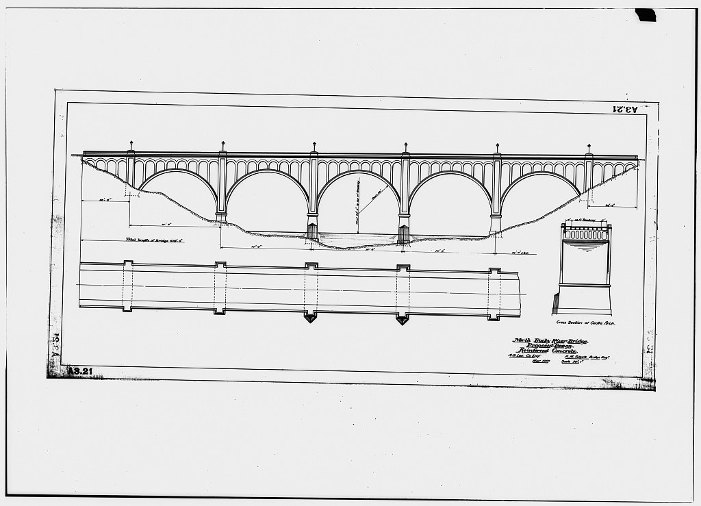
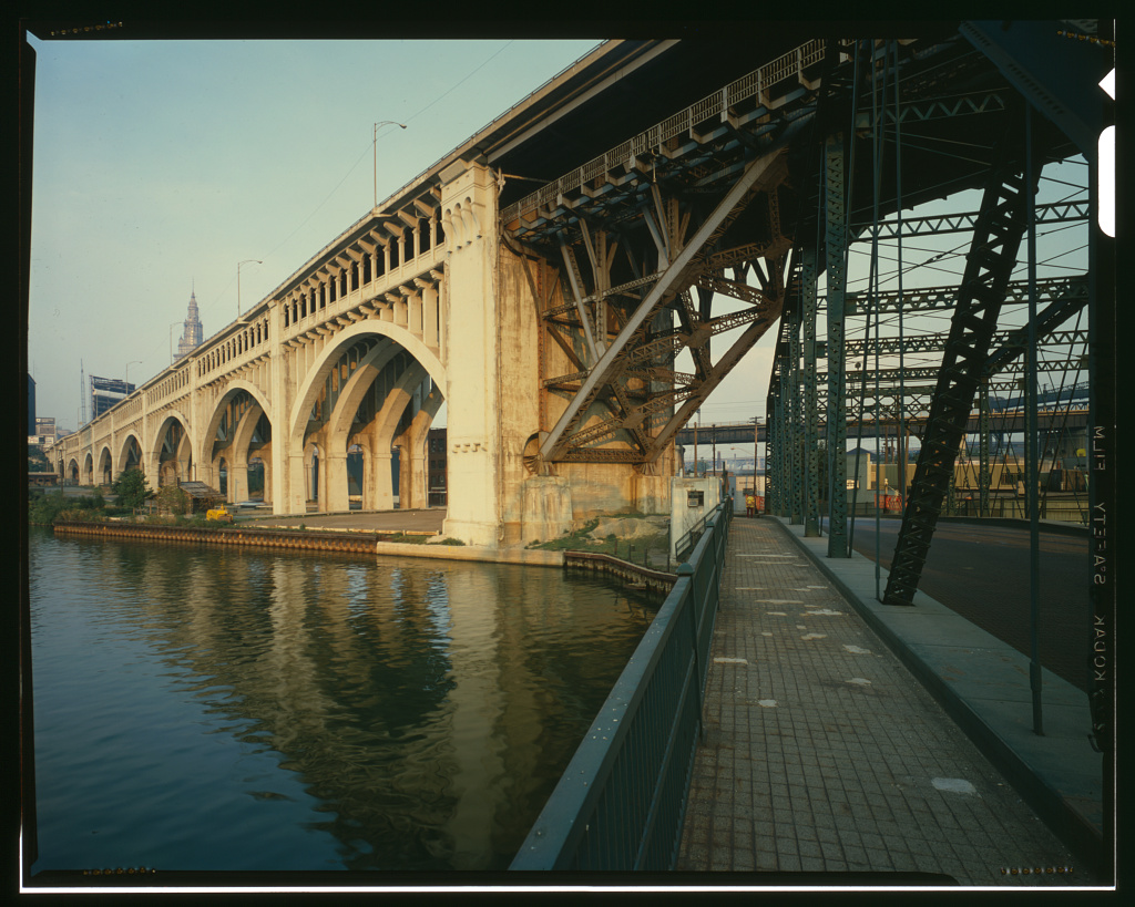
On 11 July the Commissioners resolved to "purchase a strip of land 66 feet wide, parallel with and immediately northerly of the present bridge, and to erect thereon a new bridge. On 25 July the County Commissioners voted to issue bonds in the amount of to finance a replacement structure.^ HAER No, page 4 * Physical History The design for the new bridge, prepared by Cuyahoga County Bridge Engineer A. M. Felgate under the direction of County Engineer A. B. Lea, called for a concrete structure consisting of a central twin-ribbed open spandrel arch with a 280-foot clear span, five approach arches with 44-foot clear spans, and end abutments with flanking, curved retaining walls* The bridge was designed to carry a 40-foot roadway with 8-foot sidewalks on each side.
The sidewalks were widened to 12 feet for observation platforms at the main arch piers. The roadway was designed to carry two 60-ton electric interurban cars on two tracks and two lanes of automobile traffic. This plan for the bridge at Rocky River was very similar to the Walnut Lane Bridge at Philadelphia whose central arch it exceeded by 47 feet. Thus, at the time of its design and construction, the Detroit Avenue viaduct over the Rocky River was the longest concrete arch bridge in the United States. 7 The site for the new bridge was particularly favorable to the construction of a concrete arch. The borings for the foundations showed hard shale with no seams, and the stone piers of the previous bridge proved the bearing capacity of the shale was quite high.
"These conditions were particularly favorable HAER No, page 5 / to the construction of an arch, as the horizontal thrusts could be provided for very satisfactorily," A. M. Felgate later wrote. The elimination of bridge piers in the river was especially de- sired in order to avoid the flooding problems created by spring ice jams; the long span allowed the piers to be placed where the current could not affect them. The choice of a single-span arch was favored, too, by preliminary plans showing the cost of a two- or three-span structure to be approximately the same as for a single span.
Finally, in Felgate's words, "It was also possible with a single span to evolve a design of a monumental character, the dignity of which would be commensurate with the requirements of the locality." 8 The Rocky River Bridge 3 is of the type known as Luxemburg construction, named after the Luxemburg Bridge over the Petrusse River in Germany. The essential feature of the type is a twin method of construction. Two comparatively narrow bridges are placed side by side; the space is then bridged over by a roadway. This parallel twin construction is carried through the main arch span, piers and approach spans. The piers are made in two halves and connected with a curtain wall, forming a portal. Each half is made hollow in order to save material.
According to bridge engineer Felgate, the Rocky River Bridge included three features marking an advance in the design and construction of concrete arches: the design of the main HAER No. page 6 arch with a span of 280 feet, then the longest concrete arch of its type in the world; the method of raising the compressive strength of the concrete by the introduction of embedded stone slabs; and the use of steel (rather than timber) centering during the erection of the main arch.-'-" The 280-foot arch consisted of a pair of plain concrete ribs, each 22 feet wide by 11 feet thick at the springing line and 18 feet wide by 6 feet thick at the crown. The ribs were de- signed so that the central line of pressure resulting from the dead load followed closely the center line of the linear arch.
According- ly, these ribs were not reinforced, as they were used to resist compressive stresses only, and under no circumstances could tensile stresses ever be introduced. The central arch ribs were "reinforced" by embedded slabs of stone, placed radially and separated by a space of about 6 inches. Felgate estimated that approximately 35 percent of the entire volume of the main ribs was composed of these derrick stones, or "floaters, " ^ whose purpose primarily was to increase the com- pressive strength of the concrete. Some of the slabs were over 6 feet long by 4 feet wide by 1 foot thick, and considerable time was required to place them correctly. According to Felgate, the use of the radial slabs proved cheaper than, and as effective as, 12 steel for reinforcement. W^ilbur J.
Watson, consulting engineer for the contractor, HAER No, OH-21 page 7 evolved the design for the steel centering, the essential feature of which was a three-hinged steel arch. (Centering is the tempo- rary framework, usually wooden, used in arch and vault construction; it is removed, or "struck," when the mortar has set.) The use of steel centering, according to Watson, constituted a "radical de- parture" from the usual method of building concrete arches, that of timber centering.
(The arch ribs of the Walnut Lane Bridge were cast by means of timber centering.) The contractor for the Rocky River Bridge decided that it would be cheaper to use steel , centering and that, in addition, its use would allow a clear water- way and thus eliminate the danger of destruction of the arch centers by ice in the river. Steel centering also offered greater facility of movement since, upon completion of the first arch rib, it was necessary to move the centers into position for work on the second one. This could be done easily by means of rollers. Finally, all of the 20-inch I-beams used in the centering as cross beams, stringers and joists were later to be incorporated into the bridge as floor beams for the street railway tracks.
H A word is in order here with regard to the computation of stresses in the main arch. Felgate has written that these were determined by the graphical analysis known as "Gain's method," then checked independently by algebraic methods and found to agree.-^ Tables published in the journal Engineering-Contracting illustrate the methods of deriving the stresses- in the 280-foot main arch ribs HAER No, 0H *21 page 8 under different conditions of loading.15 In the assumptions made for calculating the stresses, the concrete in the main arch rib was assumed to weigh 160 pounds per cubic foot, and all other concrete 150 pounds per cubic foot. The safe compressive strength of the concrete was assumed to be 600 pounds per square inch.
The 60-ton street cars were assumed to produce, for each half of the bridge to one side of the center line, an equivalent uniform live load as follows: for the first 10-foot width of roadway on one side of the center line, 270 pounds per square foot; for the next 10 feet of roadway, 100 pounds per square foot; and for the 8-foot sidewalk, 80 pounds per square foot. (Eccentric live loading was not considered.) The wind load was assumed to be 30 pounds per square foot of vertical surface.
Determination for stresses was made for the following conditions: (1) dead load stresses; (2) dead load plus live load stresses; (3) dead load plus one-half live load stresses; (4) dead load of arch ribs, spandrel piers and walls; (5) temp- erature stresses; (6) stresses due to shortening of the arch from thrust; and (7) wind stresses. According to Felgate, the combined stresses for all possible conditions produced their greatest effect at the spring- ing line of the main arch, where the unit stress was 566 pounds per squaxe inch. Numerous tests of the concrete made during HAER No, OH-21 page 9 i construction showed that after 30 days 6-foot cubes developed an average compressive strength of pounds per square inch; thus a safety factor of 4 was obtained.
As the age of the con- crete increased, Felgate estimated the safety factor would probably be increased to Centering for the main arch was constructed of steel in the form of a three-hinged arch. Wilbur Watson, the Cleveland consultant who designed the centering, described it in an issue of Concrete Engineering : These steel centers are composed of two parts which form a three-hinged spandrel braced arch with curved upper chord. The curved upper chord will carry cross beams composed of two 20-in. I-beams at each panel point. The cross beams will carry the stringers which are composed of four lines of 20-in. I-beams and these stringers in turn will carry the joists which run trans- versely to the axis of the bridge and carry the timber bows.
There are four of these cross beams in each panel and the bows vary in size from 12 x 12 at the springing to 3 x 12 at the crown. These bows will carry the 2-in. sheathing on which the concrete will be laid. The timber bows will be so constructed that they will be able to carry the tangential component of the weight of the arch without assistance from the steel truss. The entire vertical weight of the arch is carried to the shoes through four sets of steel wedges, one for each shoe, each set composed of four wedges.
These wedges are of annealed cast steel planed on all slid- ing faces and provided with a powerful screw for holding them in position and for lowering After the construction of the arch, the wedges will be lowered by unlocking and turning this screw and will then be jacked over into position for the construction of the second rib.
At the close of his discussion, Watson remarked that a centering very similar to his design was then being used for the Delaware HAER No, OH*21 page 4.0 Bridge on the Delaware, Lackawanna & Western Railroad at Portland, New Jersey, and that "this will probably be the standard method of construction for arches of this character in the future."^ The erection of the contractor's plant and the excavation were begun on 29 October The existing high-level bridge was continued in service while the new bridge was under con- struction parallel to and immediately downstream from it. Con- tractor for the construction of the Rocky River Bridge was The Schillinger Bros. Co. of Columbus, Ohio.
Their plant was estab- lished at the east end of the site and included an office, repair shop, boiler house, blacksmith and carpenter shops, saw mill and storehouse, cement house, storage bins, concrete plant, derricks and cableway. The cableway was a 900-foot Lidgerwood on movable towers 65 feet high. The concrete plant was located to the north of the cableway tower. Storage bins were built over the mixer, and the sand and crushed stone were delivered to the bins by a 1-yard "Williams" clamshell bucket operated by a 60-foot boom derrick. The bins were arranged so that the measuring hoppers were filled by the use of a lever which opened and closed the hopper gate. They also were provided with a series of steam pipes for heating the materials in cold weather.
The concrete mixer used was a pugmill type with a capacity of 200 yards per day. The concrete was delivered from the mixer in 1-1/2-yard buckets 18 on flat cars on a standard gauge track running to the cableway. HAER No, OH-2-1 page XI Excavation for the footings of the piers was carried down to the solid shale rock about 19 feet below the water line. The first concrete was placed on 5 December The average run of concrete was about 125 yards per day. Accord- ing to one engineer's log, by late spring of all of the footings, the west abutments, twin piers No. 1, one pier No. 2 and one pier No. 5 had been poured, and the large piers Nos. 3 and 4 had been filled to about 5 feet of their height.
9 Special attention was devoted to attaining a finish on the exposed surface of the concrete that would be uniform and "in keeping with the monumental character of the structure." In engineer Felgate's words: A facing mixture consisting of one part cement and four parts granite screenings is placed along the exposed surfaces as the concrete is cast in the forms. Steel plate separators are set against the forms so that the facing mixture may be poured simultaneously with the concrete. The separators are drawn upward as soon as the facing mixture is poured in order that the mixture may bond with the concrete. After the forms are stripped with surfaces are bush hammered and then washed with a dilute solution of hydrochloric acid, which exposes the grit of the granite facing.
The results are quite satisfactory. 20 Concrete as a material for bridge construction was in still relatively novel, and the results it yielded were frequently marvelled at by the Rocky River engineers in their field notes. One project engineer wrote; HAER No, / page 12 One cannot help but admire the beautiful finished work. . . . this extreme care of detail is economy.
Concrete must be right in the first place and no amount of labor and material spent In pointing up or patching ever makes it up to the original We look at a finely finished pier, with true bevels and chamfers, and the exposed crushed granite of the surface glittering in the sunlight, and wonder at its beauty.21 Work on the first rib of the main arch was begun on 6 August Notes kept by the resident engineer for the County show the timetable for work on the first rib: "First concrete in main arch rib placed Aug. 6. Voussoirs completed Aug. 30. Started running keys Sept. 3. Final key placed Sept. 9. Centering struck Sept.
22 The deflection of the steel centers required that the arch ribs be placed in large voussoir sections, separated by key spaces of 4 feet.23 Concrete struts were built in these key spaces with sufficient strength to carry the tan- gential component of the load. This was to prevent the concrete from sliding down the centers. The struts in keys A, B, C and D were 30 x 36 inches, 24 x 30 inches, 18 x 24 inches and 12 x 18 inches respectively, and were placed on the neutral axis of the rib, each key space containing three struts. The concrete struts were reinforced with 1-inch and, toward the crown, 3/4-inch square bars cut in 6-foot lengths. The concrete in the voussoirs and struts was (1 part Alma Portland Cement, 2 parts sand and 4 parts crushed limestone).
HAER No, OH-21 page 13 Into this were placed the derrick stones ("floaters")* which averaged feet in size. The large stones were placed with their edges toward the lagging, their width in as close to radial lines as possible. In placing the concrete, the crown sections were loaded first; the crown deflection of the steel was about 1 and 3/4 inches, with quarter points rising proportionately. The plac- ing of the succeeding voussoir sections, beginning with the haunch segments and moving toward the crown, overcame this condition and caused the quarter points to recede to their true position.
After the voussoir sections were completed, the key spaces (except for key F at the crown) were filled with a concrete of the proportion It was made very wet to insure that the struts between the sections were thoroughly surrounded. The rich mix was designed both to develop strength early and to make it equal in strength to the concrete contain- ing the derrick stones. The lowest two spaces were filled first, then the second pair, and so on until the condition was exactly the same as a stone arch ready to receive the keystone. Engineer Felgate continues the story: The temperature movements of the crown pier had been under constant observation and it was found that for a rise of approximately 30 degrees the pier raised one-quarter of an inch.
It was therefore decided to leave a joint at this key and the sides of the key space were oiled with linseed oil to prevent a bond ins the concrete. The United States weather bureau HAER No* OH^-21 page -14 was consulted and a time was chosen to key the arch when the temperature could be ex- pected to remain stationary for about two days. After this key was cast the temperature did remain stationary for two days and then rose very considerably. The crown of the steel centering came up with the temperature, with the result that the joint at one side of this key opened about one-quarter of an inch. This joint remained free from that time until the steel centers were lowered, showing that the entire radial component of the arch was taken by the steel centers.
The concrete in the arch rib was twenty-eight days old when the centers were removed, while that in the last key had been placed only nine- teen days.24 The concrete for the key at the crown was mixed com- paratively dry and thoroughly rammed into place. The top of the key was built up somewhat higher than the extrados of the adjoining sections and loaded with flat slabs of derrick stone to retain the dense mixture secured by ramming. This load was removed the day after the key was cast and the concrete was then cut down to the line of extrados. Tests of cubes of the two concrete mixtures showed that the concrete had a 30-day strength of pounds per square inch; the mixture in the keys had a 7-day strength of pounds per square inch.
Following this, it was decided to lower the centering and construct the second arch rib before the cold weather set in. This would allow the river to be entirely cleared of falsework and the dangers of the January floods and ice jams could be avoided. HAER No, OHV21 page 15 A profile of the lagging taken prior to the removal of the centering showed that the intradosal curve corres- ponded quite closely to the theoretical curve; the center point at the crown was exactly right, the average variation elsewhere in the arch was less than 1/2 inch. Intradosal and theoretical curve lengths checked to about 1/2 inch. The steel centering was jacked over into proper position for the construction of the second (north) rib.
The labor of rebuilding the forms for the rib, which were left standing during the move, was thus saved. Procedures and methods for building the second rib were exactly the same as those employed for the first one, but the rate of progress was somewhat greater due to the experience gained in building the first rib and to having larger and better shaped derrick stone. Progress was as follows: the first concrete was placed 9 October; voussoirs completed 31 October; started running keys 30 October; final key placed 6 November. The centering was struck sometime around mid-November (no exact date is available). 2 5 The spandrel arches were built next. There were four spandrel arches on each side of the main arch ribs to carry the floor system of the roadway.
These were identical in arrangement to the five approach spans. The spandrel arches each consisted of two ribs with their piers connected by a HAER No, OH^-21 page 16 curtain wall. The ribs of each arch were also connected by a 6-inch reinforced-concrete slab that acted as a strut bet- ween them. 2" Like the main arch, the five approach spans consisted of two ribs, built in pairs. The concrete for each arch rib was started at both springing lines simultaneously and carried toward the crown at an equal rate in order to keep the weight on the centering balanced. The ribs of the approach arches were 5 feet wi4e and 3 feet thick at the springing line, 4 feet wide and feet thick at the crown..
These ribs were rein- forced over the extrados at both haunches and at the intrados for 9 feet on each side of the crown by six 1-inch bars* ' The centering and forms for the 44-foot approach arches and the 21-foot spandrel arches over the main ribs were con- structed of wood. The forms, prepared in a framing yard adjacent to the work, were bolted together so that they could be removed 24 hours after the concrete had been placed to allow for the washing and brushing of the concrete surface. A subway, or hollow passageway, feet high by feet wide, was provided under both sides of the roadway for water, gas, sewer pipes and public service wiring connections. The floor of each subway was made by the 6-inch reinforced- concrete slabs that acted as struts between the pairs of ribs HAER No.
OH-21 page 17 of both the approach and spandrel arches. The roadway slab was reinforced over the subways with steel rods, but between the arch ribs it was carried by transverse 20-inch 65-pound steel I-beams embedded in concrete (those same I-beams that had been used as part of the steel centering for the main arch). The 100-pound T-rails of the street car tracks were attached di- rectly to these beams. A three-ply felt waterproofing was applied over the concrete floor of the bridge. A 1-inch layer of sand was applied next, and the roadway was paved with brick. The joints of the brick were filled with tar !" No accounts of the finishing work on the bridge the construction of the walks, balustrade and light poles are available.
Final cost of the structure was nearly less than the estimated expense,-^" Bronze plaques bear- ing the names of the County Commissioners and Engineers, the Contractor and Mayors of Lakewood and Rocky River were installed at both approaches of the completed structure. In Cleveland celebrated the County Centennial the week of 10 October "witji yells of Chippewas, flag raising by pioneer citizens, daring aerial features, and salutes from lakecraft."- Ji The week's program also included the dedication of the Denison-Harvard and Rocky River Bridges. At the Rocky River crossing, County Commissioner William F. Elrick presided over the ceremonies from a stand in the center of the bridge, A. page 18 Band music and a parade of decorated automobiles marked the occasion.
According to newspaper accounts, Ohio State Senator Thomas P. Schmidt declared the new bridge to be "typical of the inventive genius of the age." Another speaker asserted that the bridge "demonstrated that no longer did American engineers have to go to Europe for ideas on bridge construction. In fact Europeans werescoming to America . . .
The Rocky River Bridge " one of the most handsome and convenient bridges to be found in Northern Ohio," a "marvel of beauty and efficiency," in the words of one Lakewood writer-" was opened to traffic following its dedication on 12 October The burgeoning suburban population, many of whom earned their living in Cleveland, and the increasing number of automobiles would in the next twenty years earn for the bridge its dubious distinction as "one of the worst bottle-necks in Cuyahoga County""; A, HAER No. OH-21 page 19 Decline and Recent History Complaints of traffic jams on the bridge began officially in The Lakewood Chamber of Commerce that year recommended that the span be widened to six lanes and that sidewalks be hung on steel "arms" outside the bridge.-" The plan was never carried out.
Complaints in the press continued through subsequent decades, until traffic was somewhat eased in with the opening of the new Clifton-Westlake Bridge, crossing the Rocky River about a half mile to the north of the older structure. Periodic widening of the bridge approaches was also conducted in an attempt to ease rush-hour congestion. Deterioration of deck concrete became a problem as early as caused by its saturation with the.salt used to clear the roadway of ice. (The arch ribs and piers were still, and are today, surprisingly sound.") Crumbling deck concrete remains a major problem, although wooden platforms constructed along the extrados of the main arch ribs prevent the chips from falling into the river and possibly injuring pleasure boaters below.
Alterations to the bridge during its 66-year history have been as follows :^ In the south side of the west approach was widened. This involved the installation of a 50-foot span steel truss encased A, HAER No. OH-21 page 20 in concrete to carry the roadway and sidewalk which projected beyond the retaining walls. The north side of this approach was also widened, and reinforced-concrete retaining walls were added. In the south side of the east approach was widened. In the sidewalks were re surfaced, new curb facing was installed, and the original railing was replaced with a new design of reinforced concrete with posts, top and bottom rails, and vertical spindles. The streetcar rails were abandoned in with the demise of the Lake Shore Electric Railway.
The rails remained and in the bridge and approaches were re-surfaced with asphaltic concrete. In the east approach was again widened, causing four Lakewood buildings to be razed. Loose and deteriorated concrete fragments were chipped away from the middle section of the bridge deck to alleviate danger to boaters. In recent years numerous steel plates have been inserted in the bridge deck to cover holes that have developed. Asphaltic con- crete paving has been replaced over the plates. In a four-ton load limit was put into effect and the outer two lanes v closed to traffic. That same year the Ohio Department HAER No, page 24 of Highways recommended that the entire structure be removed and replaced.
The firm of Adache-Ciuni-Lynn, Inc., consulting engineers of Cleveland, is currently preparing plans for a new bridge to be constructed at the site of the historic river crossing. The new span will utilize the present site of the east approach, but the west approach is to be located some 200 feet south of that of the present span* and the old bridge will be kept in service during the first phase of construction. Complete demolition of the Rocky River Bridge appears virtually certain. It is worthwhile to note here that there has been little, if any, local support for the preservation of what Cuyahoga County Engineer Albert S. Porter has termed a "crumbling eyesore."39 A Cleveland Plain Dealer editorial of 2 March pronounced: "As for the bridge's historical significance . . .
,we doubt there is enough to warrant more than a plaque or certificate." A, HAER No, page 22 m Historical Status The historical distinction of the Rocky River Bridge rests on the fact that it was the last, rather than the first, of a group of structures to be built during the relatively brief era of unreinforced concrete construction. Predecessors to the Rocky River Bridge indeed, "the two outstanding examples of the period," according to David Plowden were the Connecticut Avenue Bridge over Rock Creek in Washington, and the Walnut Lane Bridge over the Wissahickon Creek in Philadelphia. Both were completed in "Aside from these two," Plowden has written, "the period was a barren one."^ Carl W.
Condit cites the "somewhat primitive but still handsome" Walnut Lane Bridge as the forerunner of all long- span fixed arches in the United States, noting that "the. clear span of 233 feet made this the longest bridge of its kind at the time." Condit makes no mention of the Rocky River Bridge near Cleveland, whose clear span of 280 feet made it the longest bridge of its kind just two years later. Furthermore, Condit erroneously claims that the Walnut Lane Bridge was the last long-span concrete arch bridge to be built with unreinforced ribs: "Long-span arch bridges followed the general form of the Walnut Lane structure, but it was the last with unreinforced ribs."^ 1 Research shows that the Rocky River Bridge is well A, deserving of this last distinction.
HAER No, OH-21 page 23 Obviously some confusion arises when one attempts to make claims for the Rocky River span's record in terms of pure length . If one judges it in the class of concrete arch bridges, both plain and reinforced, certainly the Rocky River Bridge pales in comparison with such later structures as the Cappelan Memorial Bridge at Minneapolis-St. Paul with a central span of 400 feet, or the George Westinghouse Bridge at Pittsburgh whose central arch had a span of 460 feet. Even the Grafton Bridge at Auckland, New Zealand, already under construction at the time of the Rocky River Bridge's completion, claimed a clear arch span of 320 feet. But each of these longer concrete arch bridges was of reinforced-concrete construction.
If one considers the Rocky River Bridge in the category of the plain concrete arch, it was both the last of its type and the longest. In terms of method of construction, the Rocky River Bridge was significant in an experimental sense: the use of steel centers for the construction of permanent masonry arches of such long span had never been tried before. "As far as this writer is aware," Wilbur Watson, the consulting engineer who designed the centers, wrote, "these were the first steel centers to be used for any but very short spans. Watson's innovation proved both economical and prac- tical fot.use in construction of the Rocky River Bridge. The HAER No.
page 24 journal Concrete Engineering , in particular, praised the "wonderful efficiency" of steel arch centering in its article announcing the completion of the Rocky River Bridge, At the same time, it pointed out that the then recent failure of the timber centering for Spokane's Monroe Street Bridge, reported in a previous issue,** was "all the more to be regretted for the reasons [ sic ] that the authorities there had under con- sideration at one time the use of steel centers similar to those used at Rocky River. The efficiency of steel centers stands out more clearly in striking contrast to this failure."*^ Did Watson's prediction come true? Did steel centering become "the standard method of construction" for long-span con- crete arches? M. K.
Hurd's recent volume on concrete formwork reports that, as early as members of the American Con- crete Institute (then called the National Association of Cement Users) were debating the merits of wood and steel formwork.* 0 As previously mentioned, steel centering was employed contem- poraneously with the Rocky River Bridge for the erection of a railroad bridge at Portland, New Jersey, ' In later years it proved itself a valuable addition to construction technology: low, short-span concrete arches continued to be supported on simple wooden trusses, but steel centering was used to great advantage on longer span arches. The twin arch rings of the Delaware. Lackawanna & Western's famous viaduct over Tunkhannock HAER No.
OH-21 page 25 Creek at Nicholson, Pennsylvania were constructed by means of movable steel centering; the type used was that of the three-hinged arch developed by Watson for the construc- tion of the Rocky River Bridge. Later, higher arches frequently utilized metal shoring in heavily braced tower assemblies.^9 But the construction of the Rocky River Bridge likely representsvthe first long-span concrete arch bridge to employ steel centering. Thus it can be recognized that the Rocky River Bridge played a significant, although transitional, role in the develop- ment of long-span concrete arch bridge construction in America, bringing to a close the era of plain concrete arch construction.
In one sense the bridge was an anomaly of its time, designed even after the advantages of reinforced concrete had been proven; in another sense, it was a daring experiment, in its then- unprecedented length and its "radical" departure from the standard method of timber centering. In terms of aesthetics, the Rocky River Bridge was designed in an age that believed concrete offered a special architectural opportunity to produce a monumental structure. 5 0 Felgate himself posited this as one of the reasons for his choice of the concrete arch type for the new bridge.
3 1 The concrete arch bridge came to be used extensively in highway bridges during HAER No, OH-21 page 26 the first half of this century, and the type was especially suited for the "memorial" bridges constructed in many major American cities. Unfortunately, as Plowden notes, the results frequently were less interesting than the steel trusses they commonly replaced, most being imitative of stone construction.^ Such was not the case with the Rocky River Bridge, which speaks for itself as a concrete structure. This has been stated best by Cleveland historian Samuel P. Orth: "Reliance has been placed on themain lines of the structure to satisfy the aesthetic properties rather than dubious ornamentation.
The structure is well balanced, dignified and beautiful, and reflects great credit upon the engineers in charge."" The Rocky River Bridge is in- eluded in Steinman and Watson's list of the "most beautiful concrete bridges in America." 0ne engineer on the project called it simply "a sermon*'in concrete. 1 " In local historical and community terms, it can be said that the Rocky River Bridge traffic "bottle-neck" or not has visually enriched its immediate environment for some 65 years.
With the establishment of the Cleveland Metropolitan Park System in more than acres of land in the Rocky River Valley have been preserved, preserving in turn the special park setting of the bridge* Historically, it can be seen that the bridge has been in large part responsible for Rocky River's transition from a rural hamlet to the small suburban city it is HAER No, OH-21 page 27 today. Its construction permitted persons employed downtown or in Cleveland's industries to commute from home to work easily. Indeed, the arch bridge is prominent in the design of the official seal of the City of Rocky River. In summary, the Rocky River Bridge quite literally marked the end of an era.
It was both the last and the longest long-span concrete arch in the United States to be built with unreinforced ribs. In addition, construction of the Rocky River Bridge represented a significant technological innovation, being the first long-span concrete arch to be constructed by means of steel, rather than timber, centering. Historically, the bridge permitted and hastened Rocky River's development from a predominantly rural community to the populous Cleveland suburb it is today. In spite of the current physical condition of the Rocky River Bridge, its last, imaginative visitors will yet enjoy a glimpse of this structure as the engineering wonder it once was. A ; HAER No, page 28 # Footnotes Ralph D.
Richards and Ron Gabel, City of Rocky River: Golden Jubilee and Ohio Sesqui-Centennial, unpaged. 2 Ibid . The term "high-level" may merit some explanation to the reader. Both Lakewood and Rocky River are situated on tableland some 70 feet above Lake Erie. The steep gorge cut by the Rocky River separates the two and thus requires a "high- level" bridge to connect them conveniently and to avoid the steep descents and ascents of a lower crossing. ^William Ganson Rose, Cleveland: The Making of a City (Cleveland and New York: World Publishing Company, p. Historian Rose writes: "The hamlet of Rocky River had a population of about seven hundred people when it was establish- ed on December 19, . . . Fine farms flourished here until the.early when the automobile began to shorten distances.
Then the transition to a suburban city of homes began, facilitated by the Rocky River Bridge . . . ." Cleveland , p. 5 (Cuyahoga County) Commissioners' Journal Record, Vol. 23, Cuyahoga County Archives, Cleveland, Ohio. ^A. (Alfred) M. Felgate is somewhat of a mystery.
Although his name appears as the "Bridge Engineer" for a number of important Cleveland bridges the Rocky River, Denison-Harvard demolished and Hilliard Road spans- no biographical data has come to light either locally or through contact with the American Society of Civil Engineers or Western Society of Engineers, Personnel records show that he was employed by the Engineering Department of the Cuyahoga County Surveyor as "deputy county surveyor" from until and as "deputy" from until In the Cleveland City Directory (Cleveland: Cleveland Directory Company, Felgate is listed as a civil engineer with the King Bridge Co. for (the first year that his name appears) and from until He is listed as a draftsman with the Watson Engineering Co.
for With the exception of his two periods of employment with the County, Felgate for all other years is listed simply as "civil engineer," with no firm name accompanying this title. The necrology file at the Cleveland Public Library shows that he died in HAER No, page 29 9 'Comparative data on the "Dimensions of Plain Concrete Hingeless Arches" constructed before can be found in Ira Osborn Baker, A Treatise on Masonry Construction , ed. (New York: John Wiley. & Sons, p. 8 A. M. Filgale [sic], "A Triumph in Concrete," The Ohio Architect, Engineer and Builder 16 (October Felgate's name has here been misspelled; attribution of author- ship to him is certain, however, since a biographical note at the end of the article identifies the writer as the engineer of the Rocky River Bridge.
^Although the bronze plaques installed at the approaches to the bridge upon its completion read "Detroit Avenue Bridge," the span has always been popularly known as the "Rocky River Bridge" and virtually every periodical of the day used this name as well. I have followed suit. 10 Filgale (Felgate), "Triumph in Concrete," p. 47. HA. L. Stevens, resident engineer for the County, claimed the percentages to be 26 for the south rib, 30 for the northern one. This was explained by the fact that larger and better shaped derrick stone was available for use in the second rib. "Further Notes, the Rocky River Bridge," Concrete Engineering 4(November 12 "Triumph in Concrete," p. 49.
Regarding the use of the derrick stones, an issue of Engineering-Contracting reported the following: "A unique feature of the arch ring concrete is that slabs of stone will be embedded, in the concrete in radial positions and quite close together; in a word the arch rings will be of a special rubble concrete. So far as we know the only precedent is the Walnut Lane Bridge of 233 ft. span recently constructed at Philadelphia, Pa. The purpose of this rubble is to increase strength and not primarily, as is ordinarily the purpose of rubble, to cut down the cost of the con- crete work. Tests made on cubes show that failure comes generally by diagonal shear.
If some resistance in the form of steel or flat stones is introduced normal to the shearing stress the ultimate strength of the construction is considerably increased" ("The Stress Sheets and Some Construction Details of a Span Rubble Concrete Arch Bridge at Cleveland, Engineering-Contracting 31 qo March HAER No, OH-21 page 30 # 13 Wilbur J. Watson, "Steel Centering for the Main Arch of the Rocky River Bridge," Concrete Engineering 4 (July 14 "Triumph in Concrete," p. 49. 15 "The Stress Sheets and Some Construction Details," pp. l6 "Triumph in Concrete," p. 50. l7 Watson, "Steel Centering," pp. See also Wilbur J.
Watson, "Steel Centering Used in the Construction of the Rocky River Bridge, Cleveland, Ohio," Proceedings of the American Society of Civil Engineers 37 (April ls Notes from John McMichael, superintending engineer for Schillinger Bros., "The Rocky River Bridge," Concrete Engineering 4 (June 19 Ibid., p. 20 "Triumph in Concrete," p. 54. 21 McMichael, "Rocky River Bridge," p. 22 Stevens, "Further Notes," p. 23xhis and the following material on the construction of the main arch ribs is taken from Filgale (Felgate), "Triumph in Concrete," pp. and A. L. Stevens, "Field Notes on the Rocky River Bridge," Concrete Engineering 4 (October 24 "Triumph in Concrete," p. 53. 25 Stevens, "Further Notes," p. 26 xhe Rocky River Concrete Bridge Near Cleveland, 0." Engineering Record 59 (23 January 92.
2 7 Ibid . 28 McMichael, "Rocky River Bridge," p. A complete description of the centering and forms used for the construction of the approach spans can be found in "The Construction of the Rocky River Bridge," Engineering Record 61 (1 January HAER No, OH-21 page 31 29 "Rocky River Concrete Bridge Near Cleveland, p. 92. 30 Stanley L. McMichael et al., Bridges of Cleveland and Cuyahoga County (Cleveland: p. 32. 31 Rose, Cleveland , p. 3 2 Cleveland Leader , 12 October Cleveland Plain Dealer , 12 October 33 Frank C. Lowing, History of the City of Lakewood (Lakewood, 0.: unpaged. 3 4 Cleveland Press , 25 July 35 Ibid.
3 6 Cleveland Press , 16 September 37 Investigation and Evaluation of the Structural Integrity of the Superstructure Frameworks of the Rocky River Bridge for the County of Cuyahoga," prepared by The Osborne Engineering Company, Cleveland, Ohio, July (Typewritten), PP. 38 Ibid., pp. and "Detroit-Rocky River Bridge" file, Office of the Cuyahoga County Engineer, Cleveland, Ohio. 3 9 Cleveland Plain Dealer , 1 March ^Bridges: The Spans of North America (New York: Viking Press, p. ^ A merican Building Art: The Twentieth Century (New York: Oxford University Press, pp.
^ 2 Tyrrell mentions the "concrete arch bridge over Rocky River on Detroit Avenue, Cleveland, Ohio" as "the longest masonry span in America." He then gives a capsule description of the structure, noting: "The main arch rings contain no steel rein- forcement, as calculations show that tension cannot occur in any part of the arch." Thus a lack of ready reference to physical data for the Rocky River Bridge does not explain Condit's or Plowden's omission of it. See Henry Grattan Tyrrell, History of Bridge Engineering (Evanston, By the Author, p. HAER No, OH-2-1 page 32 ^ 3 "Steel Centering Used in the Construction of the Rocky River Bridge," p.
"Centering Collapse on the Spokane Bridge," Concrete Engineering 5 (September 45 "The Rocky River Bridge Completed," Concrete Engineer- ing 5 (October 46 M. K. Hurd, Formwork for Concrete , 2nd ed. (Detroit: American Concrete Institute, pp. Hurd defines "formwork" as both the mold and the temporary structure (center- ing) that supports its own weight and that of the freshly placed concrete. I am aware of no work that treats centering or formwork from a historical perspective. 47 See p. 9 above. 48 A. B. MacMillan, Forms and Centering, Parts 1-2 (Scranton, Pa.: International Textbook Company, Part 2, p. 61. 49 Hurd, Formwork for Concrete , p.
50 With regard to the George Westinghouse Bridge at Pittsburgh, Steinman and Watson note that one of the chief arguments for building a concrete rather than steel bridge at this location was that "although the latter would have cost somewhat less, . . . concrete was believed to give better architectural opportunities in producing a monumental structure." David B. Steinman and Sara Ruth Watson, Bridges and Their Builders (New York: G. P. Putnam & Co., rev. and enl. ed., New York: Dover Publications, Inc., p. ^ Felgate later again employed the concrete arch type for the Hilliard Road Bridge, a three-span design with four arch ribs located just upstream from the Rocky River Bridge.
"Located in a parked [ sic ] area, [the bridge] re- quired careful consideration and proportioning to obtain good esthetic effect." See A. M. Felgate, "Modern Bridge in Parkway System of Cleveland, Ohio," Engineering News-Record 97 (25 November 5 2 Bridges , p. % \ 5 3 A History of Cleveland, Ohio , 3 vols. (Cleveland: S. J. Clarke Publishing Co., r HAER No, OH-2-1 page 33 5 Bridges and Xheir Builders , p. 390 55 "Rocky River Bridge," p. A; HAER No, page 34 Sources of Information Unpublished Cleveland, Ohio. Office of the Cuyahoga County Engineer. "Detroit-Rocky River Bridge" file. Friedman, Martin; tfelday, Chapline F.; and Wolfs, John R.
"Detroit Avenue Bridge Over Rocky River at Lake Erie: Cleveland, (Typewritten,) A report prepared in support of the Rocky River Bridge's nomination as an ASCE Historic Landmark. Wolfs, John R., Chairman, Cleveland Section, American Society of Civil Engineers History and Heritage Committee. Cleveland-Cuyahoga County Port Authority, Cleveland, Ohio. Interview, 17 December Published Baker, Ira Osbom. A Treatise on Masonry Construction . ed. New York: John Wiley & Sons, Cleveland Leader , 12 October Cleveland Plain Dealer , 29 November 12 October 13 July 1,2 March Cleveland Press , 25 July 16 September Condit, Carl W.
American Building Art: The Twentieth Century < New York: Oxford University Press, "The Construction Methods on the Rocky River Bridge, with Some Costs." Engineering-Contracting 34 (14 September Sectional plans and elevations, with description of methods employed in building a bridge with a 280-foot concrete arch span. 9 drawings, 3 photos. "The Construction of the Rocky River Bridge." Engineering Record 61 (1 January HAER No, page 35 t Detailed story of the construction of the bridge, with a discussion of problems encountered in the field and their solutions. 5 photos. Filgale [ s ic ], A. M. "A Triumph in Concrete." The Ohio Architect, Engineer and Builder 16 (October Cuyahoga County Bridge Engineer Felgate's account of the design and construction of the Rocky River Bridge. 2 photos.
Plowden, David. Bridges: The Spans of North America . New York: Viking Press, Plowden's volume, like Condit's, helps construct the historical framework of concrete arch construction necessary for a judgment of the historical status of the Rocky River Bridge. "Proposed Concrete Bridge at Cleveland to Be Largest in Existence." Concrete Engineering 3 (April Brief, general discussion of the proposed design for the Rocky River Bridge. 1 drawing, 1 artist's rendering. "The Rocky River Bridge." Concrete Engineering 4 (June Field notes from John McMichael, superintending engineer for Schillinger Bros.; description of contractor's plant and first stages of construction. 2 photos.
"The Rocky River Bridge." Concrete Engineering 4 (July Detailed illustration and discussion of the con- struction of the minor arch ribs, with notes by Wilbur J. Watson on the use of steel centering for the main arch. 12 photos, 2 drawings, 1 artist's rendering. "The Rocky River Bridge Completed." Concrete Engineering 5 (October Praise for steel centers and the "longest concrete arch in the country." 2 photos. "The Rocky River Concrete Bridge Near Cleveland, 0." Engineer- ing Record 59 (23 January v \ General discussion of the specifications for the bridge, 3 drawings. HAER No, OH-21 page 36 # Rose, William Ganson. Cleveland; The Making of a City .
Cleveland and New York: World Publishing Company, "Steel Centering for Concrete Arches." Concrete Engineering 4 (October Description of the construction and use of steel centering; field notes by A. L. Stevens, resident engineer for the County, on the construction of the first main arch rib. 11 photos, 4 drawings. Stevens, A. L. "Further Notes, the Rocky River Bridge." Concrete Engineering 4 (November Notes on the erection of the second (north) rib of the main arch. 5 photos, 1 drawing. "The Stress Sheets and Some Construction Details of a Span Rubble Concrete Arch Bridge at Cleveland, 0." Engineering-Contracting 31 (10 March Description of the general structural features of the Rocky River Bridge, with stress computations. 2 drawings. Tyrrell, Henry Grattan.
History of Bridge Engineering . Evanston, By the Author, Chapter on "Solid Concrete Bridges," with a brief description of the Rocky River span and its contemporary competitors. Watson, Wilbur J. "Steel Centering Used in the Construction of the Rocky River Bridge, Cleveland, Ohio." Pro- ceedings of the American Society of Civil Engineers 37 (April Watson describes in detail his "radical departure" from the usual method of masonry bridge construction, with the use of steel (rather than timber) centering for the main arch. 5 photos, 3 drawings. HAER No, OH-21 page 37
Engineering Information
General Statement Structural Character: Concrete arch bridge of parallel twin construction. Condition of Fabric: Good to poor. While the main arch ribs and piers remain stable, the deck concrete has deteri- orated severely due to permeation with the salt used to clear the roadway of ice. A load limit of four tons has been imposed since August and the two outer lanes are closed to traffic. Description Overall Dimensions: The bridge is 708 feet long and 60 feet 4 inches wide. Foundations: The main arch piers are mass concrete resting on shale about 19 feet below the water line.
Structural System: The Rocky River Bridge consists of a % central twin-ribbed open spandrel arch with a 280-foot clear span, two approach arches on the east and three on the west, each with 44-foot clear span, and end abutments with flanking, curved retaining walls. The rise of the central arch is feet. Cross-sectional dimensions of the main arch ribs are: 11 feet deep by 22 feet wide at the springing line and 6 feet deep by 18 feet wide at the crown. The concrete in the main arch ribs is unreinforced; it is used to resist compressive stresses only and the central line of pressure from the dead and live loads follows closely the center line of the linear arch.
Large derrick stones (aver- aging feet in size) are embedded in radial lines in the concrete of the ribs, intended to raise the compressive strength of the arch. The approach and spandrel arches and the floor system are heavily reinforced with steel. Special Decorative Details: All exposed surfaces of the bridge are covered with a crushed granite-rich mix, placed at the same time the concrete was poured into its forms to insure proper bonding. Bronze plaques installed on the rail- ing end,\posts at both approaches to the bridge read as follows: Detroit Avenue Bridge Commissioners of Cuyahoga County, John G. Fischer. Fred R. Mathevs. H. L. Vail. R. J. Mackenzie. W. F. Elrick. County Engineers, A. B. Lea. F. R. Lander. Bridge Engineer, A. M. Felgate. Contractors, The Schillinger Bros.
Co, Mayor of Rocky River, Mark Mitchell. Mayor of Lakewood, N. C. Cotabish. HAER No, page 38
The original filed report, and the sheets the survey produced. Those published here appear above.
Also surveyed in Cuyahoga County
24 of 114 records shown
The federal survey recorded these other structures elsewhere in Cuyahoga County. These are the other structures
they measured and filed a report on, longest report first.
 Block
Block