Rocket Engine Testing Facility, GRC Building No. 205, NASA Glenn Research Center, Cleveland
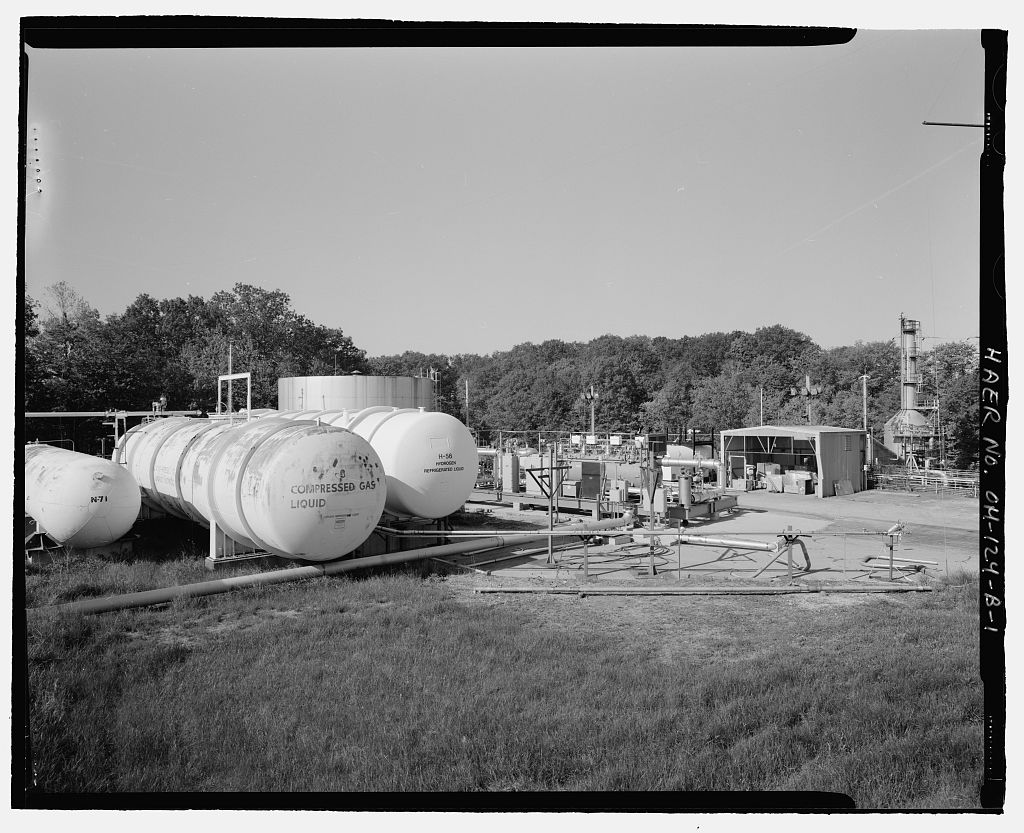
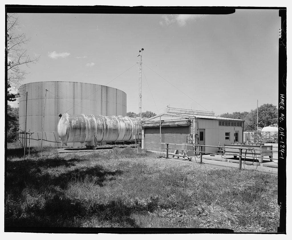
Rocket Engine Testing Facility, GRC Building No. 205, NASA Glenn Research Center, Cleveland, Cuyahoga County, OH. Surveyed as HAER OH-124-B, with 1 photograph and a 2,625-word written history.
From the record
“The Rocket Engine Test Facility Complex is a National Historic Landmark, and Building 205 is included in the description of the site on the National Historic Landmark nomination form.”
Written record, HAER OH-124-B survey. Machine-read text.
surveyed by the federal HAER program as HAER OH-124-B · the record runs 2625 words · one of 115 surveyed structures published for this county.
1 photograph from the federal survey record, Library of Congress.
Significance
111 words
Source document
Quoted word for word from HAER OH-124-B.
Not written, edited or summarised by this site.
The Rocket Engine Test Facility Complex is a National Historic Landmark, and Building 205 is included in the description of the site on the National Historic Landmark nomination form. Building 205 is located approximately northeast of the Rocket Engine Test Cell in Building The significance of Building 205 lies in its relationship to the entire reactant distribution system for the Rocket Engine Test Facility. Building 205 housed a compressor and automated control system used to pressurize gaseous helium to pounds per square inch (psi) for distribution throughout the complex. Compressed helium was used as the energy source to pump liquid oxygen into rocket engines during testing. Building 205 was constructed ca.
Written history
116 words
Source document
Quoted word for word from HAER OH-124-B.
Not written, edited or summarised by this site.
This documentation was initiated on May 15, in accordance with a Memorandum of Agreement among the Federal Aviation Administration, National Aeronautics and Space Administration (NASA), The Qhio State Historic Preservation Officer, and the Advisory Council on Historic Preservation. The City of Cleveland plans to expand the Cleveland Hopkins International Airport. The NASA Glenn Research Center Rocket Engine Test Facility, located adjacent to the airport, must be removed before this expansion can be realized. To mitigate the removal of this registered National Historic Landmark, the National Park Service has stipulated that the Rocket Engine Test Facility be documented to Level I standards of the Historic American Engineering Record (HAER).
This project was initiated to fulfill that requirement.
Written history
987 words
The headings the report itself prints. Each one jumps to where it begins.
Source document
Quoted word for word from HAER OH-124-B.
Not written, edited or summarised by this site.
Robert C. Stewart Historical Technologies, West Suffield, Connecticut ROCKET ENGINE TEST FACILITY -
Grc Building
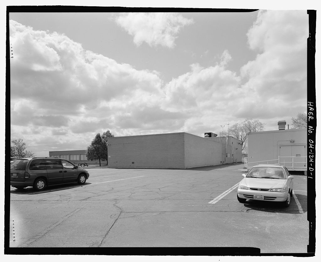
No.205 (Rocket Propulsion Test Facility- Propellant Transfer and Storage Area Building HAER NO. OH-124-B Page 2 Description: Building 205 is located approximately northeast of the Rocket Engine Test Cell in Building The single-room, one-story structure covers a surface area of about square feet. The light construction consists of framing made of pipe uprights welded to channel iron cross members. Light I-beams support the roof. Opaque fiberglass panels form the exterior walls, while translucent fiberglass panels cover the gabled roof and admit natural light into the building interior. Sheathing has been removed from the front of the building. Building 205 is a purely functional building devoid of any ornamentation.
The significance of this building lies in its relationship to the liquid oxygen distribution system for the Rocket Engine Test Facility. Function: The Rocket Engine Test Facility did not use conventional electrically driven centrifugal pumps to deliver liquid oxygen to the test cell. The safe handling and transport of liquid oxygen posed special problems, since this substance boils at C and specialized pumps and piping materials are needed to safely transfer it from one vessel to another. With its low boiling point, significant evaporative losses can occur during transfer. At the Rocket Engine Test Facility, liquid-nitrogen-filled jackets surrounding the major pipes minimized the loss of liquid oxygen.
With a boiling point of C, the liquid nitrogen in the pipe jackets prevented the liquid oxygen from boiling, and thereby minimized evaporation. 1 Losses of liquid nitrogen were inconsequential in their impact on accurate test results, but as a reactant in the test engines, the liquid oxygen had to be carefully measured to obtain valid test data. The liquid oxygen tank in the Building 202 oxidant pit was also jacketed in a bath of liquid nitrogen. 2 When the Rocket Engine Test Facility complex was built in commercially available mechanical pumps for handling cryogenic fluids were not ideally designed for forcing liquid oxygen at high flow rates into rocket engines during testing.
To overcome the problems inherent in pumping liquid oxygen directly, the designers developed an indirect pumping system. The system used pressurized gaseous helium to transfer the pumping energy of electrically driven compressors to the liquid oxygen supply system. Building 205 housed the compressor and automated control system used to pressurize helium gas to psi for use in pumping liquid oxygen. The compressor in Building 205 pressurized the helium, which was then piped to the liquid oxygen tank in the Building 202 oxidant pit. An inlet at the top of the main liquid oxygen tank connected it to the gaseous helium supply system. The inlet to the liquid oxygen outlet pipe was located below the level of liquid oxygen in the tank.
Control valves admitted pressurized helium at psi with a flow rate ofup to 3.5 pounds per second into the tank. The pressurized helium 1 John H. Perry, ed., Chemical Engineers' Handbook (New York: McGraw Hill Book Company, Inc., 2 Drawing No. - ROCKET ENGINE TEST FACILITY - GRC BUILDING No.205 (Rocket Propulsion Test Facility- Propellant Transfer and Storage Area Building HAER NO. OH-124-B Page 3 pushed the liquid oxygen into the outlet pipe and out to the test rig at the rate necessary to obtain the engine's maximum thrust. 3 History: The structure currently known as Building 205 was not part of the original Rocket Engine Test Facility construction phase.
Building 205 does not appear in a photo of a Rocket Engine Test Facility scale model that represented the facility as originally constructed. The model shows a series of large outdoor metal tanks and a small compressor or other piece of equipment just south of the current site of Building 4 A aerial photograph of the Rocket Engine Test Facility shows outdoor tanks and a tanker truck on the site of Building 5 The current Building 205 appears, however, on aerial photographs of the Rocket Engine Test Facility dating to and 6 Original construction drawings could not be found for Building possibly because it is a small prefabricated shed.
Building 205 supported Rocket Engine Test Facility operations until the entire facility was deactivated in Fiberglass cladding has been removed from the main (east) elevation of the building, and the original equipment has been removed from the interior. Building 205 is currently used for surplus equipment storage. The Rocket Engine Test Facility complex, including Building is scheduled for demolition to make way for the expansion of Cleveland Hopkins International Airport. Conclusion: The Rocket Engine Test Facility oxidant distribution system was an ingenious solution that used simple, proven technology to transfer liquid oxygen at controlled flow rates into test engines that required large amounts of oxidant for short periods.
In conjunction with the load cells that weighed the liquid oxygen, this distribution system also enhanced the accuracy of gravimetric measures of the flow rate and total usage of oxidant during a test. Building 205 played a key role in the operation of this system from its construction ca. until the Rocket Engine Test Facility closed in 3 Drawing No. CE-101632 - 4 NASA Photo Number ( l 5 NASA Photo Number ( 6 NASA Photo Numbers ( ( ), and ( ). ROCKET ENGINE TEST FACILITY -- GRC BUILDING No.205 (Rocket Propulsion Test Facility - Propellant Transfer and Storage Area Building HAER NO. OH-124-B Page 4 Sources of Information/Bibliography A. Engineering Drawings: NASA Lewis Research Center - Cleveland, Ohio Facility Plan and Equipment Layout REIF Area Master Plan Drawing No.
CF - NASA Lewis Research Center - Cleveland, Ohio High-Pressure Propellant System for Rocket Engine Test Facility Oxygen System Schematic Diagram Drawing No. -- NASA Lewis Research Center - Cleveland, Ohio Rocket Engine Test Facility Oxidant Tank Details Drawing No. B. Interviews: Repas, George, Hardware Design Engineer Interview by the author, 15 November West Suffield, Connecticut, Telephone interview, Hardlines Design Company, Columbus, Ohio C. Secondary
Sources
692 words
The headings the report itself prints. Each one jumps to where it begins.
Source document
Quoted word for word from HAER OH-124-B.
Not written, edited or summarised by this site.
Butowsky, Harry. "Rocket Engine Test Facility, National Register of Historic Places Nomination." Washington, United States Department of the Interior, National Park Service, Dawson, Virginia P. "Rocket Propulsion Research at Lewis Research Center," 28 1h Joint Propulsion Conference AIAA/SAE/ ASME/ASEE, July AIAA-92- NASA Contractor Report National Aeronautics and Space Administration. "Historic Photographs of the Rocket Engine Test Facility, On file at NASA Plumbrook Research Center, Sandusky, Ohio. Perry, John H., ed. Chemical Engineers' Handbook. New York: McGraw-Hill Book Company, ROCKET ENGINE TEST F AGILITY --
Grc Building
No.205 (Rocket Propulsion Test Facility - Propellant Transfer and Storage Area Building HAER NO. OH-124-B Page 5 Sloop, John. Liquid Hydrogen as a Propulsion Fuel. Washington, NASA Special Publications No. Thomas, Wayne. "Description of the Rocket Engine Test Facility." Cleveland: Lewis Research Center, ROCKET ENGINE TEST FACILITY - GRC BUILDING No.205 (Rocket Propulsion Test Facility - Propellant Transfer and Storage Area Building HAER NO. OH-124-B Page 6 NASA LEWIS RESEARCH CENTER gal \ CLEVELAND, OHIO ~~ SERVO!' 0 GRADES ~ - () ~ LOWER SOUTH ROAD ro \ LOWER SOUTH ROAD ~ RETAINING WALL \ ~ . 'I ,g ~ litl er, -g -3 llll\\lllilL-il~ \ ? ~ ' 7I I ~~ ;o '"Ij ( ) ~ ~ 8. rn ~ -3 '"O a 8 z ~ rn ~ -3 rn ~ I / : / @ ~ ~ /. [ .. , ~ 1 ! lbW .
r -3 -3 '"1 > '"Ij er, RETENTION TANK /i?({ (~_ ~f ~a c o .0 ct' SCRUBBER/SILENCER _< ~ ~ '"' r._ -3 nf\:BUILDI~ 0.. z. )I z. VJ. I FIRST FLOOR PLAN KEY PLAN ~a ~ ~ ;::o REVISED JULY REF. NO. CE-101340 & > ~ (') ROCKET ENGINE TEST FACILITY 16 0 16 32 rn > co t:::::.:::::iia l ;::o '"' C BUILDING NO. 202 SCALE - FEET Z ro ._ SOURCE: PAGE - ROCKET ENGINE TEST FACILITY o;r . ~ 0 COREL50 SOFTWARE SCANNING AND ADDITIONS 0 Z BY STEWART - NOVEMBER ~ e-: a '"O.:..&; z ~ NNO (JQ ro f'" o N co 0 V, - V, ROCKET ENGINE TEST FACILITY - GRC BUILDING No.205 (Rocket Propulsion Test Facility- Propellant Transfer and Storage Area Building HAER NO. OH-124-B Page 8 RETF PRESSURE VESSEL WORKING PRIMARY WATER VESSEL LTA SUNK!
No OS: PRE$URE CAPACITY IRcrr REMARl<S MSSELS VOLi.Ji,$ No {P:ilb) DWG No A GHz i 5tF FT 1 CF622!illillifflll l!OTILE FARM e a liOOO 2W Ot25CF 900 n r.oiJ'il FWI C LMt I ISOO 115 FTJ (E7')1'l4 U - ~-- l1 E F LH2 GIi~ . GN2 4 2 I 995 GAi. iSIJ,292 SCF SCF 1~3 nl ( CF Ff3 FT 3 U:622577 RIM TMIIC 4KHe aorn. FARM G LOX I 411 &AL ss FTa CE1016?,'Z t0i2322! H LOX I 3% &AL sa FT' CE101843 tFIOl2M I A~~'t 2 3S 4116AI./EA 55 FT 3 J rf~ I 561 GA.L FT3 (1=6'U578 K WATER I 115 FT3 8-l!ALL L , WATER l SOOD 5B7 6Al FT~ Cffo'Z2518 M GOX.
I W: (Id 1UBOIJ N Glie,911 - ' I SCF ?JOO FT3 fAl'iM p LN2 I 150 28,000GAL CFf,3,CZO DEWAR Q LN2 2 100 150 GPM PUMP R LN2 I &S ~L - 'iEMOOR DEWAR r:: CFIOl53'5 CFU2!27 DEWAR - - s LM, I 125 18KGAL - T LH2 I 6K bOK CHI A455762 IIAPORIZ!R - w &Me I 6K 160 (OMPRE550R X GHe I M!l&1LE ru&ERS - y I DILE TUBERS AA CO2 I 350 ,f K V/.llOIUZEP. 1AMK AS CO;_ I &K !!I&'!.fo FT 5 STOR..SE TAHI< AC LU~ I i DU dk: tQ&~.o FT 3 STORAGE TA JK AD 2 !i.00 GAL FT1 - Yi.D01l.1Z R Tl"IK AE LOX I :tlnO GAi. FT3 (Ff,'ZIS74 DEWAR -,;!mi AF f Nt 9 41( FTl 4MPIS& 60TU fAIM AG GMz I 50K /lt;eli.E TU6ERS AH GHz I S0K lU&ERS AI I 6K U, i>Pr.l CFIOIS41 VJIPORIZl:R AJ LNz I 55 4000GAL D WM AK LN2 I 600 3006AL DEWAR AL GHe I fiOK-15K SCF MO&llf TUSERS AM (l~ 2 GH'i!
BOTTI.ES A~ G.\\e I \SOO SCF 1\0 \.OX,~ I soo 53\l.'I-M "' OOG.AI.. '?IQA\00 'iUJ"1. '"'i:A.1.1'1(, A.fl' \ ,ooo !aO ~}a~ S'!!,l"!o!,H\ -00 RI.IN "';l>.tJIC
The original filed report, and the sheets the survey produced. Those published here appear above.
Also surveyed in Cleveland
24 of 83 records shown
The federal surveyors worked through Cleveland building by building. These are the other structures
they measured and filed a report on, longest report first.
 Block
Block