Rocket Engine Testing Facility, GRC Building No. 206, NASA Glenn Research Center, Cleveland
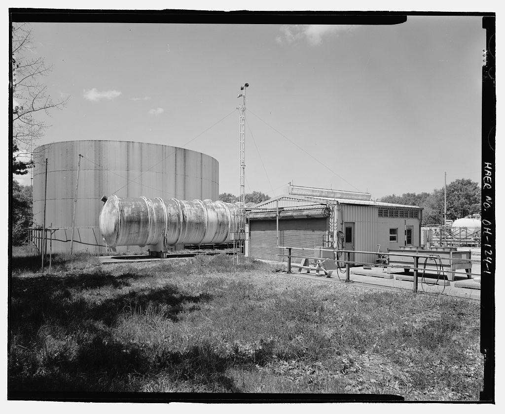
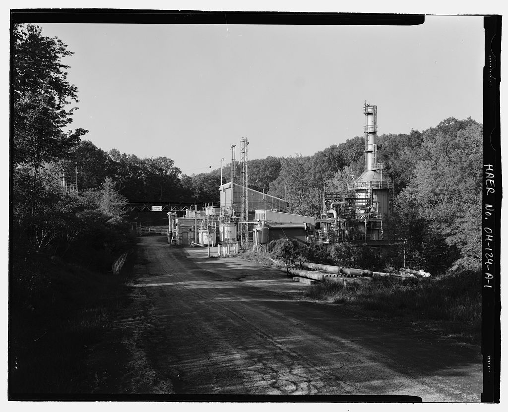
Rocket Engine Testing Facility, GRC Building No. 206, NASA Glenn Research Center, Cleveland, Cuyahoga County, OH. Surveyed as HAER OH-124-C, with 1 photograph and a 1,770-word written history.
From the record
“The Rocket Engine Test Facility Complex is a National Historic Landmark, and Building the Cryogenic Vaporizer Facility, is included in the description of the site on the National Historic Landmark nomination form. 1 The floor of Building 206 is located at elevation on the east bank of the creek bed above the test stand, about northeast of Rocket Engine Test Facility Building The Building 202 floor is at elevation placing it below the Cryogenic Vaporizer Facility.”
Written record, HAER OH-124-C survey. Machine-read text.
surveyed by the federal HAER program as HAER OH-124-C · the record runs 1770 words · one of 115 surveyed structures published for this county.
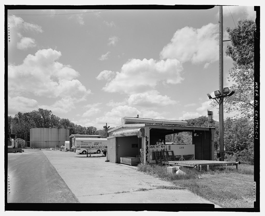
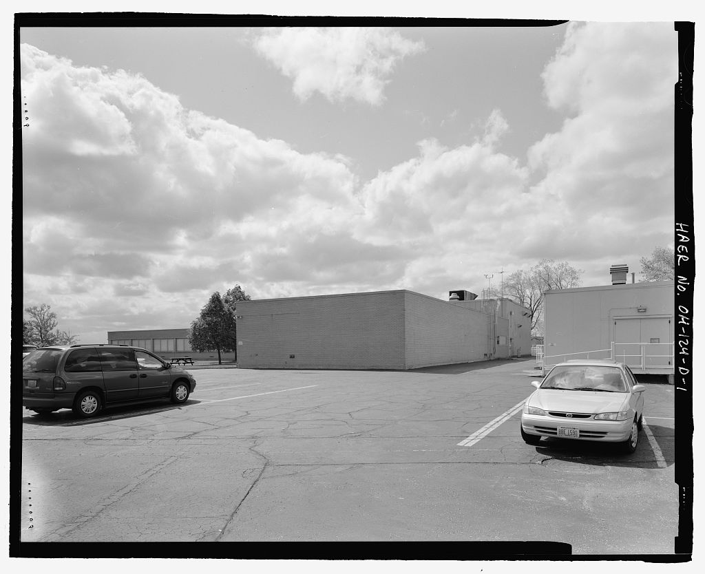
1 photograph from the federal survey record, Library of Congress.
Significance
130 words
Source document
Quoted word for word from HAER OH-124-C.
Not written, edited or summarised by this site.
The Rocket Engine Test Facility Complex is a National Historic Landmark, and Building the Cryogenic Vaporizer Facility, is included in the description of the site on the National Historic Landmark nomination form. 1 The floor of Building 206 is located at elevation on the east bank of the creek bed above the test stand, about northeast of Rocket Engine Test Facility Building The Building 202 floor is at elevation placing it below the Cryogenic Vaporizer Facility. Building 206 was part of the gas distribution system for the Rocket Engine Test Facility. This building housed a liquid nitrogen vaporizer and a gaseous nitrogen compressor. Nitrogen was used in the facility to actuate pneumatic valves where electrically actuated solenoid valves controlling oxygen or hydrogen might be hazardous.
Building 206 was constructed in
Written history
187 words
Source document
Quoted word for word from HAER OH-124-C.
Not written, edited or summarised by this site.
This documentation was initiated on May 15, in accordance with a Memorandum of Agreement among the Federal Aviation Administration, National Aeronautics and Space Administration (NASA), The Ohio State Historic Preservation Officer, and the Advisory Council on Historic Preservation. The City of Cleveland plans to expand the Cleveland 1 Some maps and other sources refer to the original cryogenic vaporizer facility as "Building to distinguish it from the more recently constructed Building 206A, which is located east of the Rocket Engine Test Facility water reservoir. This report refers to the cryogenic vaporizer facility simply as "Building ROCKET ENGINE TEST FACILITY - GRC BUILDING No. 206 (Rocket Propulsion Test Facility - Cryogenic Vaporizer Facility Building HAER No.
OH-124-C Page 2 Hopkins International Airport. The NASA Glenn Research Center Rocket Engine Test Facility, located adjacent to the airport, must be removed before this expansion can be realized. To mitigate the removal of this registered National Historic Landmark, the National Park Service has stipulated that the Rocket Engine Test Facility be documented to Level I standards of the Historic American Engineering Record (HAER). This project was initiated to fulfill that requirement.
Written history
1149 words
The headings the report itself prints. Each one jumps to where it begins.
Source document
Quoted word for word from HAER OH-124-C.
Not written, edited or summarised by this site.
Robert C. Stewart Historical Technologies, West Suffield, Connecticut Description: Building 206 was part of the gas distribution system for the Rocket Engine Test Facility. This structure housed a liquid nitrogen vaporizer and a gaseous nitrogen compressor. It may have been designed to handle other gases as well, since the wiring was protected against explosion. The one-story gable-roof building covers a surface area of 597 square feet and is sheathed in corrugated metal panels. Since ventilation was an important consideration for Building a vent was constructed on the roof along the full length of the ridgeline. Louvered vents on the gable end of the building provided additional ventilation.
An overhead coiling door on the building's gable end measures approximately 16' wide and provides access to the interior and equipment. An isolated concrete-block control room in the southwest corner features a small window that allowed personnel to monitor the machinery bay. The control room had a switchboard of twelve explosion-proof switches that controlled motors and fans in the building. Also, the structure was equipped with wiring, telephones, and lighting that were explosion-proof and would therefore not provide a source of ignition. Function: The most cost-effective means of transporting nitrogen was to transfer it in liquid form.
Liquid nitrogen could be moved in large mobile Dewars, 2 which maintained the nitrogen below its boiling point of .8 C and limited loss through evaporation. Inert, non-flammable gaseous nitrogen was used in the Rocket Engine Test Facility to actuate solenoid valves and to pressurize the fire control and hydrocarbon fuel systems. Liquid nitrogen had to be vaporized before it could be used in the facility. A nitrogen vaporizer essentially consisted of a heat exchanger.3 Liquid nitrogen was first fed through a pump/compressor, pressurized to pounds per square inch (psi). The highly pressurized 2 Sir James Dewar invented the Dewar flask in This invention provided insulation against the transfer of heat through conduction, convection, or radiation.
The Dewar flask was commercialized in as the "Thermos" flask. 3 John H. Perry, ed. Chemical Engineers' Handbook (New York: McGraw-Hill Book Company, l ROCKET ENGINE TEST FACILITY --
Grc Building
No. 206 (Rocket Propulsion Test Facility - Cryogenic Vaporizer Facility Building HAER No. OH-124-C Page 3 liquid then flowed through a network of pipes to the vaporizer. Fans pulled ambient air across the exterior surface of the pipes. The liquid nitrogen in the pipes warmed and boiled, forming high- pressure nitrogen gas. The gas was then piped throughout the Rocket Engine Test Facility for use. Pressure reducers provided gaseous nitrogen at other pressure levels, including or psi gauge for test rigs. A system to supply high-pressure cooling water to test rigs was also pressurized with nitrogen. 4 One major use for high-pressure nitrogen gas was the actuation of solenoid valves that controlled gaseous hydrogen, nitrogen, and helium.
Nitrogen supplied to solenoids at hydrogen Dewars actuated those valves. 5 The use of nitrogen under pressure to actuate remote valves located in proximity to flammable liquids or gases was common practice in the Engineering texts of the period refer to pneumatic actuators as "pneumatic diaphragm motors." Pneumatic actuators, generally operated by compressed air, gaseous nitrogen, or hydraulic fluid, were used to open sliding stem- controlled valves, dampers, rotary plug valves, and a variety of remotely controlled devices. 6 Gas-actuated valves, controlled by electrically operated solenoids, could be rapidly opened or closed. Hydraulic fluid was used to pressurize the engine's fire control systems.
The vacuum condition capabilities added to Test Stand B in were maintained by pressurized nitrogen. Nitrogen powered the ejectors used to simulate the vacuum of space in the test stand. Two gas ejectors powered by the facility's nitrogen supply system created the desired extra-terrestrial conditions. Normally this type of ejector was steam-powered, but the availability of a high-pressure nitrogen supply on the site made the use of this gas cost-effective. 7 History: The site of Building 206 was left as undeveloped lawn space during the original construction phase of the Rocket Engine Test Facility from The location appears as empty space in a photograph of a scale model representing the facility as originally constructed. 8 Historic 4 Drawing CE-183170 - 5 Ibid.
6 Perry, 7 Ejectors use the venturi effect to create a vacuum. An ejector is a simple form of vacuum pump, with no moving parts. It consists of a gas nozzle that discharges a high-velocity jet of nitrogen across a suction chamber connected to the vacuum chamber. The nitrogen traps the gas to be evacuated and then passes into a venturi-shaped diffuser, which converts the velocity energy of the nitrogen into pressure energy. Ejectors normally used high-pressure steam to provide the energy necessary to create a vacuum, Since the Rocket Engine Test Facility had access to ample supplies of pressurized nitrogen, it was cost-effective to use this source rather than steam. 8 NASA Photograph Number ROCKET ENGINE TEST FACILITY - GRC BUILDING No.
206 (Rocket Propulsion Test Facility- Cryogenic Vaporizer Facility Building HAER No. OH-124-C Page 4 aerial photographs of the facility taken in and also show the Building 206 site as empty lawn. 9 An original construction drawing for Building 206 is dated August 23, 10 and the facility appears on a aerial photograph of the Rocket Engine Test Facility. 11 Construction drawings indicate that NASA Lewis Research Center engineering staff members designed Building The building shows little or no evidence of additions, remodeling, or other alterations. Building 206 continued to support the gas distribution system for the Rocket Engine Test Facility until the entire Rocket Engine Test Facility was closed in Building 206 has been vacant since the shutdown and is currently not in use.
The Rocket Engine Test Facility, including Building is scheduled for demolition to accommodate the expansion of Cleveland Hopkins International Airport. Conclusion: Building the cryogenic vaporizer facility, housed equipment that served a critical function at the Rocket Engine Test Facility. This structure provided pressurized nitrogen gas to perform a variety of essential tasks, especially in environments where electrical motors or actuators could not be used safely. The building served in this capacity from the time of its construction in until the Rocket Engine Test Facility closed in 9 NASA Photograph Numbers ( ( and ( 10 Drawing 11 NASA Photograph Number ( ).
Rocket Engine Test Facility Grc Building
No. 206 (Rocket Propulsion Test Facility- Cryogenic Vaporizer Facility Building HAER No. OH-124-C Page 5 Sources of Information/Bibliography A. Engineering Drawings: NASA Lewis Research Center- Cleveland, Ohio Rocket Engine Test Facility Gaseous Nitrogen System South 40 - Building No. 202 psig Gaseous Nitrogen Supply System Schematic Drawing No. - NASA Lewis Research Center- Cleveland, Ohio Rocket Engine Test Facility Gaseous Nitrogen System South 40 - Building No. 202 psig Gaseous Nitrogen Supply System Schematic Drawing No. B. Interviews: Repas, George, Hardware Design Engineer Interview by the author, 24 October West Suffield, Connecticut, Telephone interview, Hardlines Design Company Columbus, Ohio C Secondary
Sources
188 words
The headings the report itself prints. Each one jumps to where it begins.
Source document
Quoted word for word from HAER OH-124-C.
Not written, edited or summarised by this site.
Butowsky, Harry. "Rocket Engine Test Facility, National Register of Historic Places Nomination." Washington, United States Department of the Interior, National Park Service, Dawson, Virginia P. "Rocket Propulsion Research at Lewis Research Center," Joint Propulsion Conference AIAA/SAE/ ASME/ ASEE, July AIAA-92- NASA Contractor Report National Aeronautics and Space Administration. "Historic Photographs of Rocket Engine Test Facility, On file at NASA Plumbrook Research Facility, Sandusky, Ohio. Perry, John H., ed. Chemical Engineers' Handbook. New York: McGraw-Hill Book Company, Sloop, John. Liquid Hydrogen as a Propulsion Fuel. Washington, NASA Special Publication No. ROCKET ENGINE TEST FACILITY -
Grc Building
No. 206 (Rocket Propulsion Test Facility- Cryogenic Vaporizer Facility Building HAER No. OH-124-C Page 6 Thomas, Wayne. "Description of the Rocket Engine Test Facility." Cleveland, Ohio: Lewis Research Center, ROCKET ENGINE TEST FACILITY -- GRC BUILDING No. 206 (Rocket Propulsion Test Facility- Cryogenic Vaporizer Facility Building HAER No. OH-124-C Page 7 (1) <D "' NO o, "= gai 1 00 " .. U/\S'x'lr-lf/l/1~ a:i a r- 'SI" 000 'SI" l!) co 'SI" l!) -st Location Map - Rocket Engine Test Facility Ancillary Buildings GRC Buildings 206 and Blockhouse USGS Lakewood, Ohio Quadrangle
The original filed report, and the sheets the survey produced. Those published here appear above.
Also surveyed in Cleveland
24 of 83 records shown
The federal surveyors worked through Cleveland building by building. These are the other structures
they measured and filed a report on, longest report first.
 Block
Block