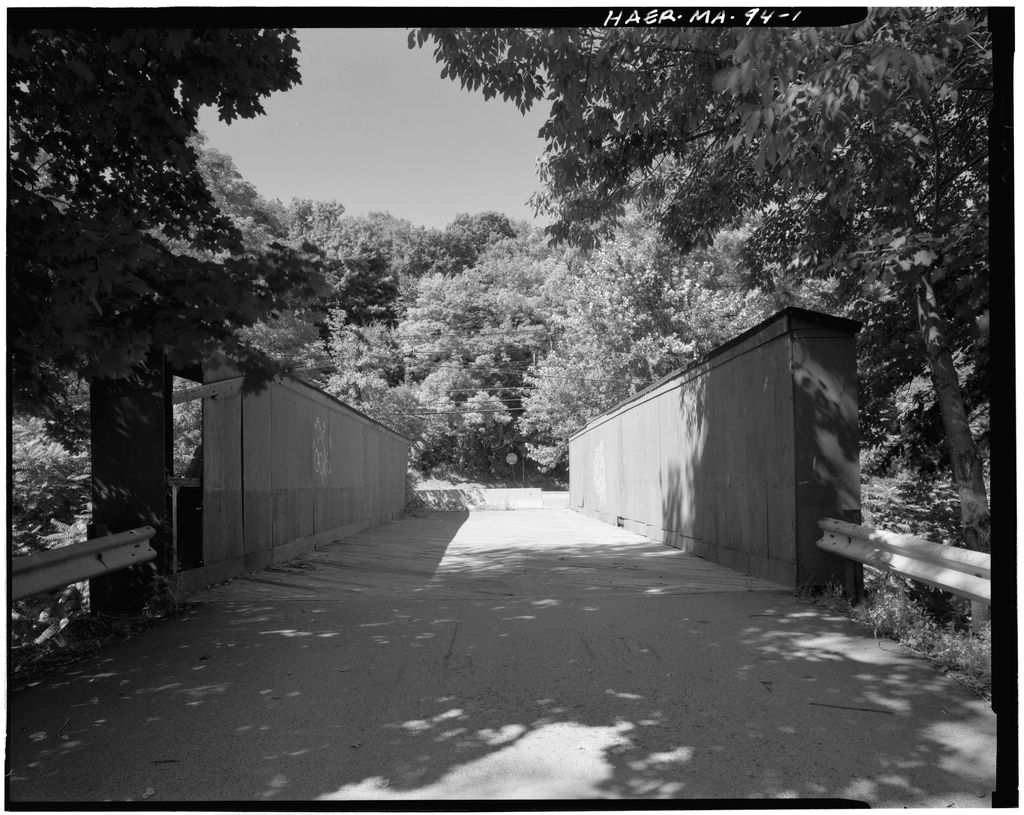
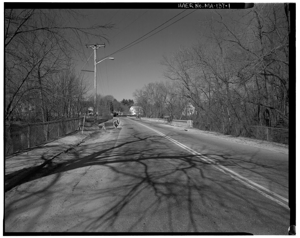
Documentation of the Clark Street Bridge is part of the Massachusetts Historic Bridge Recording Project, conducted during the summer of under the co-sponsorship of HABS/HAER and the Massachusetts Department of Public Works, in cooperation with the Massachusetts Historical Commission. John Healey, HAER Historian, August BOSTON & MAINE RAILROAD: CLARK STREET BRIDGE HAER No. MA-94 (page 2) Description The Clark Street Bridge is a boxed, timber Howe pony truss span. It carries a suburban road across the tracks of the Boston & Maine Railroad, at mile post on the Fitchburg Main Line, and was formerly designated Bridge No. 16 on that line. The span measures overall, and when completed in it spanned a steeply-curved, triple-tracked route, occupying a deep cutting. Today only two tracks remain.
The width across the trusses was originally however the southern truss has been moved inwards to give an overall width of The trusses are deep, resting on stone abutments. The north abutment has straight, stepped wingwalls, and is crudely executed in dry-laid rubble stone. The south abutment is of broken range ashlar, with angled, stepped wingwalls. The truss design is of the developed Howe form.1 All truss components are made from "hard pine" (southern pine).2 The upper chord is comprised of triple "chord sticks."3 The "sticks" are arranged with their long axes vertical, and are separated from each other by 1-inch gaps to give a total chord width of Each component is made up of two lengths of timber simply butted.
The components are then clamped together by bolts bearing on washer plates, and are separated from each other by "filler blocks" at the same point. The distribution of the clamping bolts is irregular, a pair being located about each timber joint, with intermediate bolts where the separation between joints is great. The longest chord stick is these pieces being located on the outer and inner members, in order to stagger the jointing pattern. The central member is made up of two equal lengths butted at the center. The upper chord was built with a 2-inch camber. At their ends the upper chord members have a lipped mitre to receive the inclined endposts. The inclined endposts are comprised of two single members set at 45 degrees, and clamped together as in the top chord.
The inclined endposts attach to the lower chord by means of a cast iron shoe plate. The plate is cast to receive the endposts, and is notched obliquely into the bottom chord, the assembly is clamped together by obliquely-set bolts passing through both endposts and bottom chord. Like the upper chord, the lower chord is made up of three distinctive sticks, however in detail they differ significantly. They are while their longest length is The joint details are wholly different. Five-foot long oak splice blocks are used to effect a joint. Both the chord members to be jointed, and the block are notched to form a tightly-fitting keyed joint, able to withstand tensile stresses. The assembly is clamped in place at each end by two through bolts made up against washer plates, as in the top chord.
Likewise, joints are staggered such that the outer, and inner members have the longest timber lengths. The inner member has short end timbers linked by a long central length. The absence of joints at the center requires additional through bolts, together with filler blocks in this area. The ends of the chord are reinforced by a doubling "bolster" , below which the trusses are blocked onto the abutment. The chords were built with a 2-inch camber. The web system is comprised of eight panels, each measuring The main compression diagonals are paired members. Their dimensions vary in the BOSTON & MAINE RAILROAD: CLARK STREET BRIDGE HAER No.
MA-94 (page 3) end panels they are in the four remaining inward panels they are The counter diagonals are also compressive members, they are absent in the end panels, but occur in the remaining central panels, passing through the paired main diagonals to which they are through bolted. At all except the center panels, the diagonals rest on triangular bearing blocks of cast iron. They are of a standardized design, in which the base is splined to slot into the bottom chord, the diagonals being located by dowelling into pre-cast holes. At the central panel point all diagonals have a 2-inch tenon, mortised into the chord sticks. The verticals are tensile "upset rods" of wrought iron. They are paired, and pass through the outer chord sticks, to be made up by bolts bearing against plates.
At all panel points except that at the center the paired rods pass through the center of the cast bearing block. The upset rod dimensions vary in diameter, increasing from IV" at the center through and from 2" to 2V at the hip. Within each panel, three floor beams are hung from below the bottom chord. This contrasts with the more usual single beam resting upon the chord at the panel point. The beams are fastened to the chord by a single bolt, passing through the slots between the chord sticks to be made up against wooden blocks spanning the top of the chord. Alternate beams are fastened through the inner, and then outer slots between the three chord sticks. The overall length of the beams varies to reflect this arrangement.
The deck stringers comprise of members on V centers, to which was nailed a deck of double transverse planks, each of 2" thickness. Today the deck is of single planks only. All deck components were also of "hard pine". The individual trusses were clad in spruce boarding, capped by a narrow mono- pitched roof. Bridge Design While most American railroads were concerned to replace their wooden bridges with iron and steel spans, the Boston & Maine continued to build wooden spans for both rail and overbridges into the present century.4 In out of a total of Boston & Maine bridges were of wooden construction, and while the proportion of wooden spans was decreasing, more than half of the replacement spans built that year were also of wood.
In addition to trestles and stringer spans, the Boston & Maine was a proponent of the developed Howe truss, the "modified Howe truss" (essentially a multiple king rod design, lacking the intersecting pattern of compressive diagonals, and counter diagonals), and the Town lattice forms. The latter form was used where larger individual spans were required. The developed Howe form was generally used for rail spans of between 30' and Above this span length, Town lattices were used. In overhead highway bridges the modified Howe truss was said to be used "almost exclusively", however the 67-foot Clark Street span apparently required the fully-developed Howe form.
Never a wealthy railroad, the Boston & Maine's continued use of what might be regarded as an obsolescent form, was apparently dictated by economy. The savings in first costs could be considerable, a 120-foot span constructed in iron was said to cost a Howe truss of similar length would cost and a Town lattice would cost It was said that below this BOSTON & MAINE RAILROAD: CLARK STREET BRIDGE HAER No. MA-94 (page 4) length of span the relative cost advantages of timber increased, while above it they were said to "decrease rapidly." Such cost comparisons were made on the basis of an understanding of the materials and designs, drawing partly on intuition and observation, but also on a more scientific understanding of their properties. In comparing the suitability of Town vs.
Howe designs, it was realized that there was a trade off between timber qualities and quantities. The Town bridges required relatively larger quantities of timber, however the design lent itself to the use of readily available--and therefore, cheap--native New England spruce. The Howe bridge demanded less material, but the stresses within the timbers were higher. Experience had, by this time, shown that spruce was an unsuitable material for a Howe bridge, the more costly southern pine, imported from Georgia, proving to be a more suitable timber. At 650 lbs./sq.in. spruce was known to have only 65 percent of the compressive working strength of southern pine, while with a tensile working strength of 800 lbs./sq.in. it possessed 80 percent of the capacity of southern pine.
Experience had shown that, if employed in Howe bridges, spruce tended to warp and crack. The relatively shorter available lengths of spruce required extra joints, which both weakened the structure, and increased production costs. The relative difference in durability between spruce, said to have a life of six to seven years, and southern pine with a life of twelve to fourteen years was perhaps less important, for when enclosed in a housing, and kept clean and well ventilated both were said to last for between forty and fifty years. The effect of weather and "blast cut" required the replacement of transverse beams, and stringers every twenty years.
The combination of vehicular traffic above, and the "blast cut" of locomotives below, necessitated the renewal of deck planks every ten to twelve years.6 The Boston & Haine had found that the saving in materials inherent in the Howe design offset their additional costs when the span was below 60 feet in length. At long, the Clark Street Bridge apparently demonstrates that these economies could be extended in the less highly-stressed highway overbridge. The bridge clearly represents a continuity of early New England railroad bridge-building practice into the twentieth century.
The basic configuration of the Howe truss, characterized by outward-sloping wooden compression members, and wrought-iron tensile verticals, was improved early in its life by the addition of counter diagonals, and hip verticals that could bear compressive loads. Bolsters were added beneath the extremities of the bottom chord in order that the shear from the hip timber might be better transferred to the abutments. Such features evolved as an intuitive response to observations of the behavior of the truss under conditions of live and abnormal loads. Early American timber truss assembly required the cutting of complex mortise and tenon joints. By the early decades of the nineteenth century triangular wooden bearing blocks were being used as a means of affecting union of members.
By the cast-iron bearing blocks, similar to those at Clark Street, were being used for this purpose. Superimposed upon those features that are part of the American intuitive master carpenter tradition, may be seen the influence of the trained engineer. The mechanical behavior of the timbers were known and used to proportion the members for safety and economy. The execution of the joints clearly shows BOSTON & MAINE RAILROAD: CLARK STREET BRIDGE HAER No. MA-94 (page 5) that the nature of the stresses present were well-understood. Particularly, the nature and quantity of material used in the bottom chord joints has been calculated to withstand the tensile forces that the chord sticks might bear.
The graduation in dimensions of the upset rods also indicates a subtle deployment of material based upon calculation. The hanging of the transverse beams from below the bottom chord, was intended to bring about a more even distribution of load across the chord sticks and web members. When this beam was placed upon the chord it was found that the inner sticks and diagonals carried a disproportionate load. Railroad History The Fitchburg Railroad was chartered in and authorized to build a line from West Cambridge to Fitchburg. The line was opened through Belmont to Waltham the following year. Originally a single track, it was doubled to Fitchburg between and The Fitchburg Railroad remained independent until when it became part of the Boston & Maine system.
The Central Massachusetts Railroad was incorporated in and construction work began in It was not until that it was opened from Hudson through to North Cambridge, its single track sharing the right of way with the Fitchburg route through Belmont. The Central Massachusetts was operated by the Boston & Lowell from until when it was dissolved upon purchased by the Boston & Maine. From the outset, the line appears to have occupied a cutting as it curved westward from Belmont Station. Although level grade crossing elimination programs were carried out both east and west of the area in the twentieth century, the line does not appear to have been depressed beneath Clark Street.
The designation of the tracks after was thus: North- Central Massachusetts, Center-Outbound Fitchburg, South-Inbound Fitchburg. (Although the north track was removed in the description below refers to these arrangements, rather than those pertaining today.) The railway deed maps show how the two railroads routes evolved in the immediate vicinity of Clark Street Bridge.7 Land acquired for the original single Fitchburg track is occupied by the central track, designated for the Fitchburg Railroad. Land acquired for the doubling of the Fitchburg tracks in & is occupied by the north track, designated for Central Massachusetts trains. Land acquired in at the time of construction of the Central Massachusetts is occupied by the south track, designated for the Fitchburg Railroad.
The purpose of these changes clearly demonstrates opportunism on the part of the directors of the Fitchburg Railroad. It appears that in negotiating with the newcomer over shared rights of way into Boston, the Fitchburg extracted the advantage in having the Central Massachusetts pay for a curve-reduction program. Thus, on approaching Clark Street from the east, the old and sharply-curved route of the Fitchburg was transferred to the Massachusetts Central which in compensation had to acquire land to the south, and dig a deeper cutting to accommodate a straightened line for the Fitchburg tracks. In the Concord Street grade crossing elimination program was carried out by depressing the tracks one-eighth of a mile to the east of Clark Street.
BOSTON & MAINE RAILROAD: CLARK STREET BRIDGE HAER No. MA-94 (page 6) The wholly-different styles of masonry work in the two abutments testifies to the widening of the lines. The rubble stone north abutment was built by the Fitchburg Railroad company, and the date given for its construction is this date apparently coinciding with the first Clark Street Bridge. The southern abutment was built by the Massachusetts Central, apparently in some four years after the construction of the line. It is unclear whether this is an error in the records, or whether the relocation of the Fitchburg lines took place after the opening of the Massachusetts Central.8 Upon acquiring the Fitchburg Railroad, the Boston & Maine appropriated to improve the bridges on this route.
It is not clear whether the rebuilding of the Clark Street Bridge in was part of this program. The replacement coincides with the Belmont grade crossing elimination program, and although there is no evidence of the excavations extending as far west as Clark Street, it could be seen as providing a convenient opportunity to replace the span. Maintenance When the bridge was surveyed by the Interstate Commerce Commission, seven years after its construction, the trusses and their housing were given a life span of thirty-three years, while the floor members were said to be good for another eleven years, although the deck planks had been renewed in Accordingly, in the entire floor system was replaced.
The southern truss was moved inward at this date.9 In the truss housing, floor beams, stringers and deck were renewed, and the whole structure was raised on timber blocks.10 Today the bridge is closed to traffic, the outer sides of the housings are in very poor condition, while the inside sheathing boards have been replaced in plywood. Inspection of the truss members shows them to be in good condition, and apparently original. Massachusetts has the largest number of housed wooden pony truss bridges known to survive nationally. Six survive within the Commonwealth; New Hampshire retains four, two of which carry the tracks of the Berlin Branch line; Maine and Quebec both have two, while Ohio and Pennsylvania have one each. BOSTON & MAINE RAILROAD; CLARK STREET BRIDGE HAER No.
MA-94 (page 7) ENDNOTES 1. Boston & Maine Railroad, "Fitchburg Line: Bridge No. original plans, File Boston & Maine cabinets, Bridge Section, Massachusetts Department of Public Works, Boston. 2. Interstate Commerce Commission, "Interstate Commerce Commission Valuation Notes, Boston & Maine Historical Society Collection, Mogan Library, University of Lowell, Lowell, Massachusetts. 3. J. Parker Snow, "Wooden Bridge Construction on the Boston & Maine Railroad," Journal of the Association of Engineering Societies. July pp. 4. Ibid. 5. Professor Daniel Schodek, Harvard University Graduate School of Design, personal conversation with author. 6. Interstate Commerce Commission, "Valuation Notes, 7.
Fitchburg Railroad Deed Maps, Boston & Maine Railroad Historical Society Collection, Mogan Library, University of Lowell, Lowell, Massachusetts. 8. Interstate Commerce Commission, "Valuation Notes, 9. Boston & Maine Railroad, "Fitchburg Line: Bridge No. 16, Plans for Repairs, File Boston & Maine cabinets, Bridge Section, Massachusetts Department of Public Works Boston. 10. Interstate Commerce Commission, "Valuation Notes, annotated to indicate work carried out in 11. Nelson Lawry, Rollinsford, New Hampshire, Personal conversation with author. BOSTON & MAINE RAILROAD; CLARK STREET BRIDGE HAER No. MA-94 (page 8)
Boston & Maine Railroad. Plans for "Fitchburg Line: Bridge No. Located in File Boston & Maine cabinet, Bridge Section, Massachusetts Department of Public Works, Boston. Bradlee, Francis, The Boston and Maine Railroad: A History of the Main Road. With its Tributary Lines. Salem, Massachusetts: Essex Institute, pp. "Bridge Bridge Section files, Massachusetts Department of Public Works, Boston. Interstate Commerce Commission. "Interstate Commerce Commission Valuation Notes, Boston & Maine Historical Society Collection, Mogan Library, University of Lowell, Lowell, Massachusetts. Snow, J. Parker, "Wooden Bridge Construction on the Boston & Maine Railroad," Journal of the Association of Engineering Societies. July pp. 31- 43. Waddell, J.A.L. The Designing of Ordinary Iron Highway Bridges.
New York: John Wiley & Sons,
 Block
Block