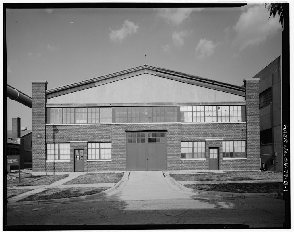
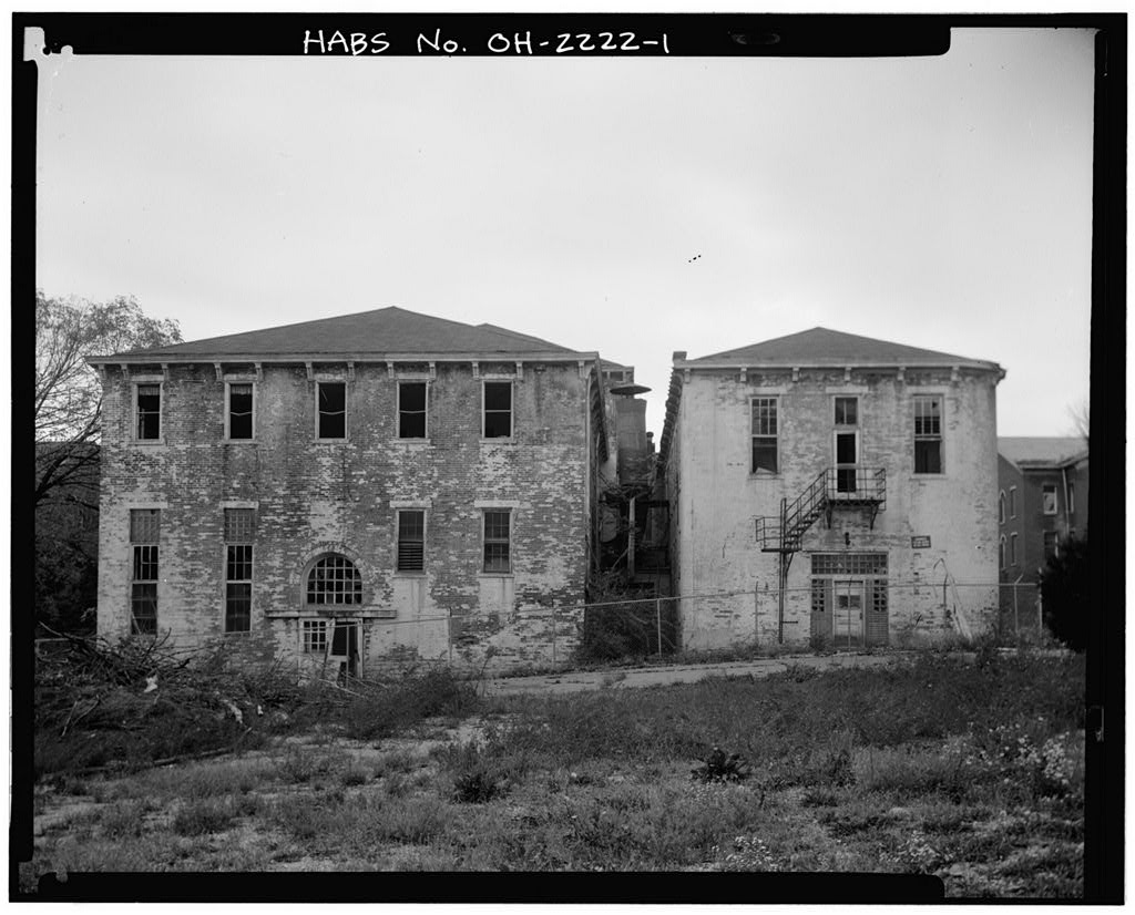
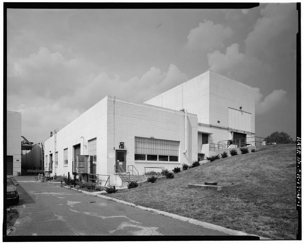
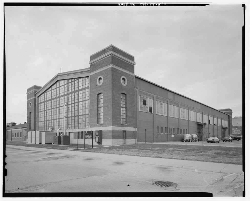
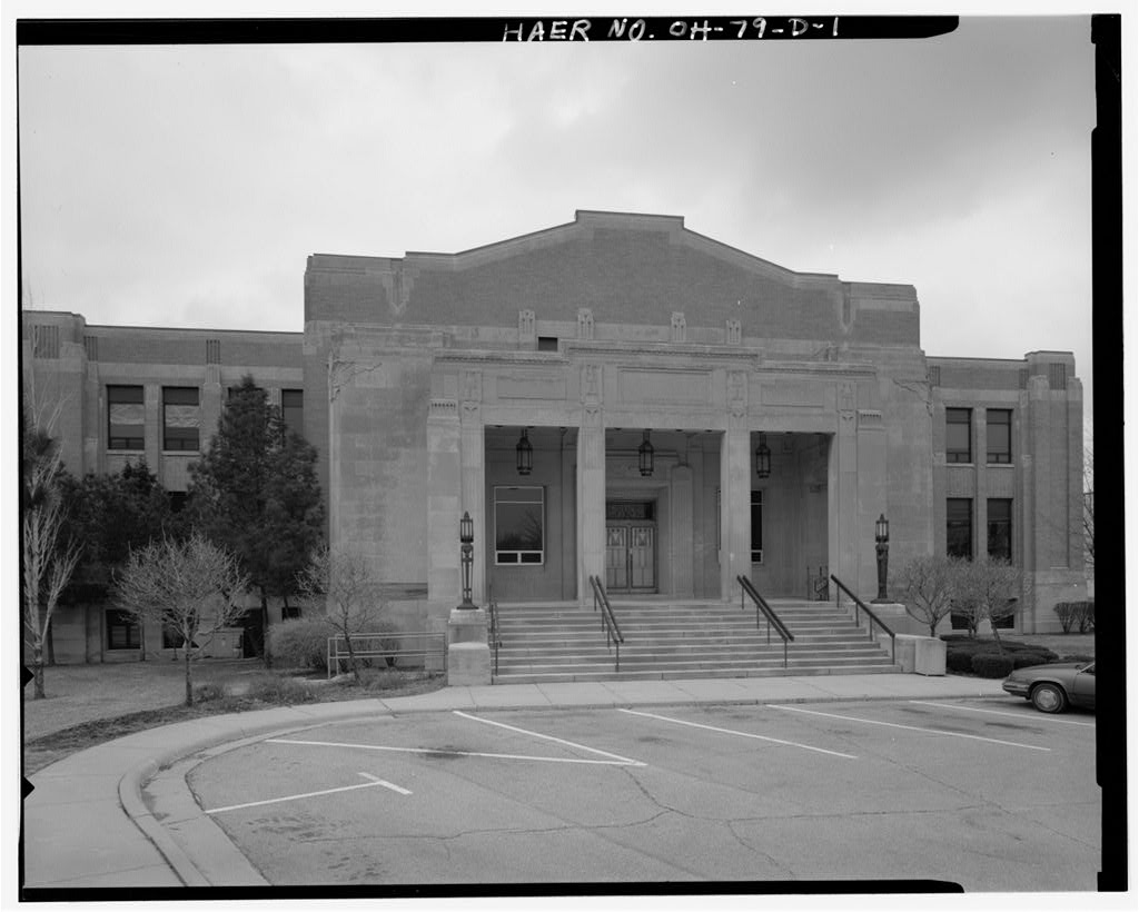
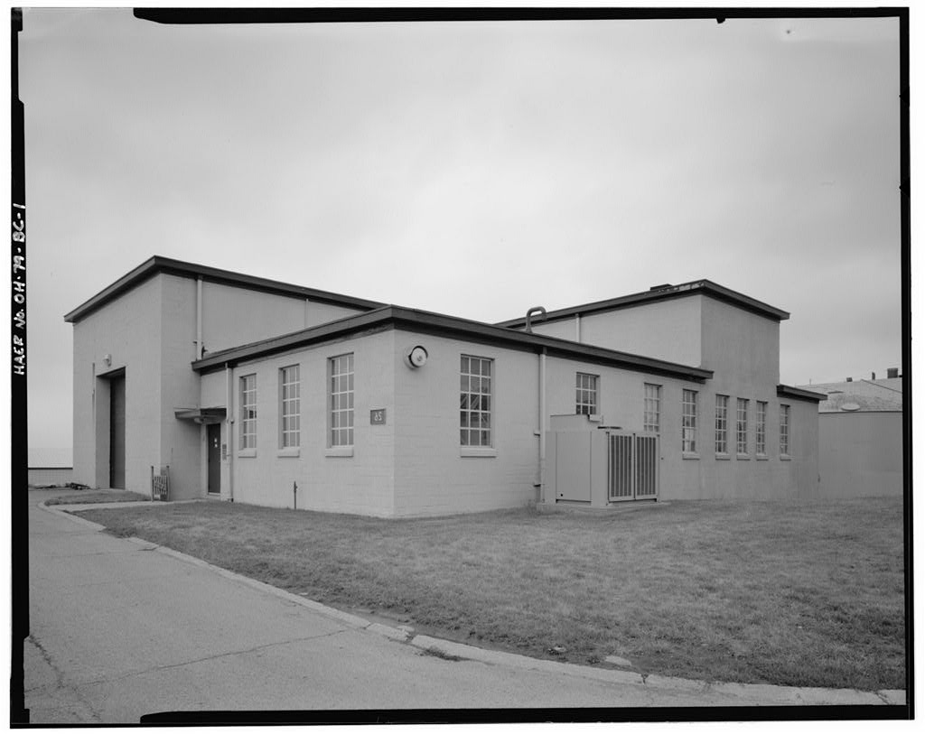
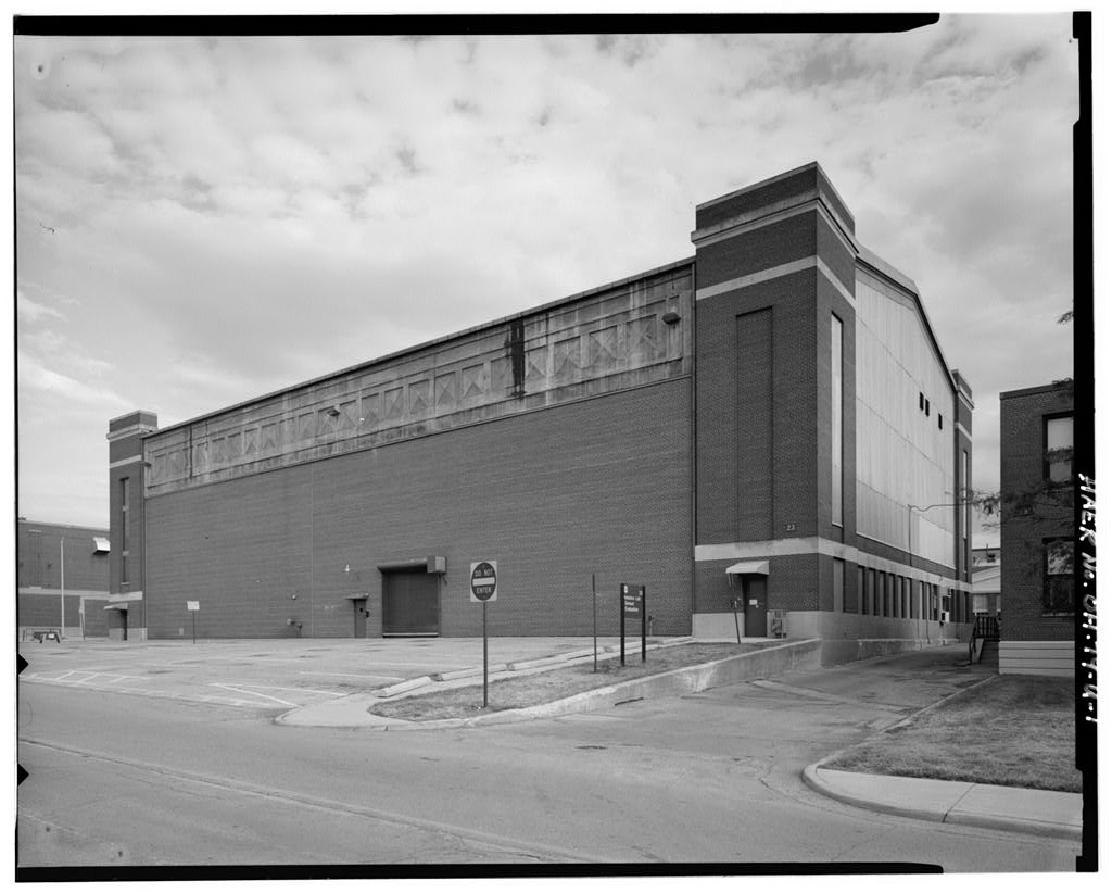
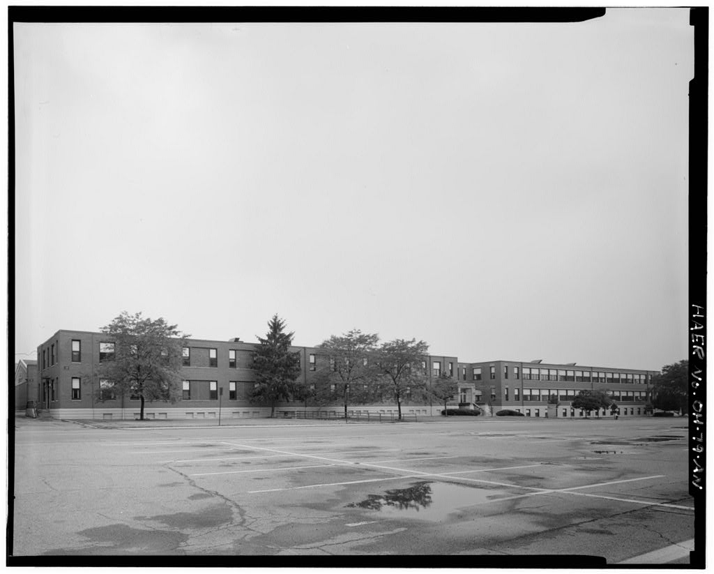
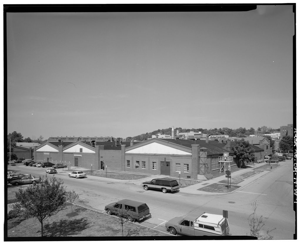
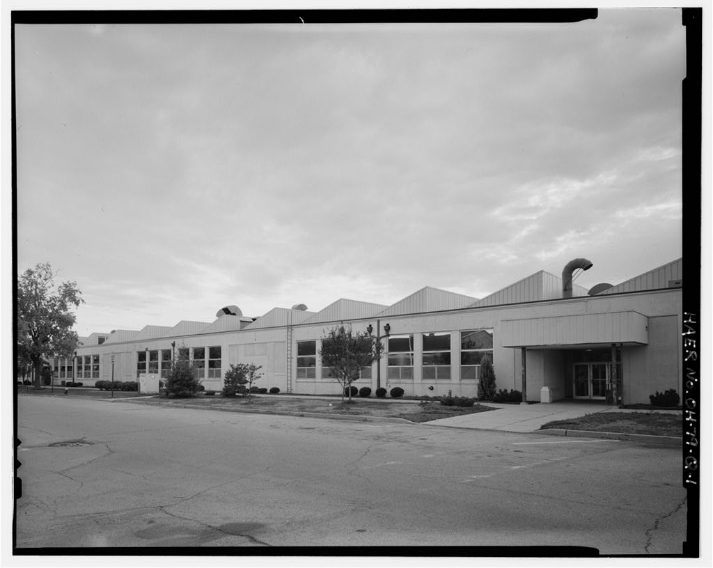
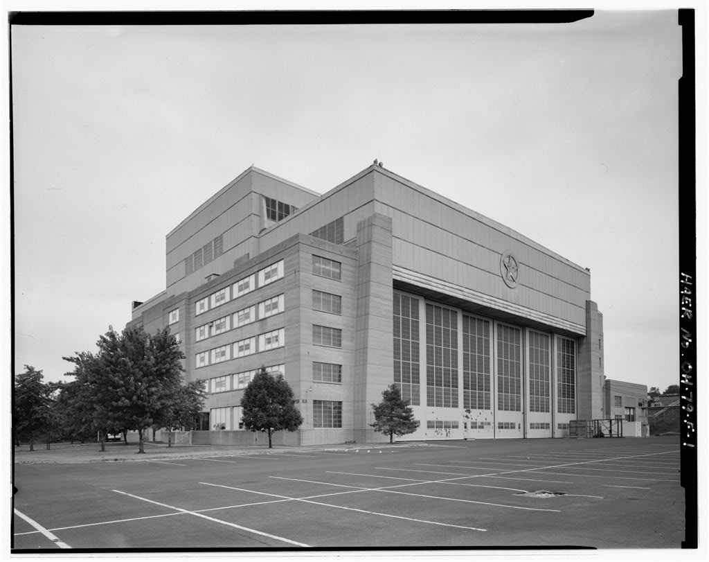
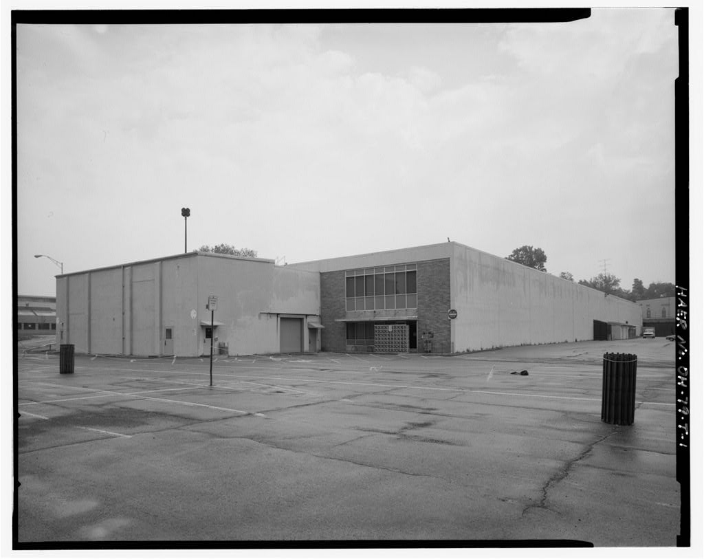
This two-story, six-course American bond brick building has a low-pitched, front-gabled roof with a copper entablature. Exhibiting elements of the Greek Revival style, rectangular columns with concrete capitals decorate the corners. Below the concrete stucco gables of the east and west ends, fifteen bays of twelve-pane windows with concrete sills run the entire width of the building. The second story of the north side contains twelve window bays, with two nine-pane and two twelve- pane windows in each bay. The ground floor contains similar bays with large, steel, double doors leading to the generator room. The south side, now obscured by Building 20, has eleven window bays. At the west end, large metal double doors are flanked by single doors, themselves flanked by nine-pane windows.
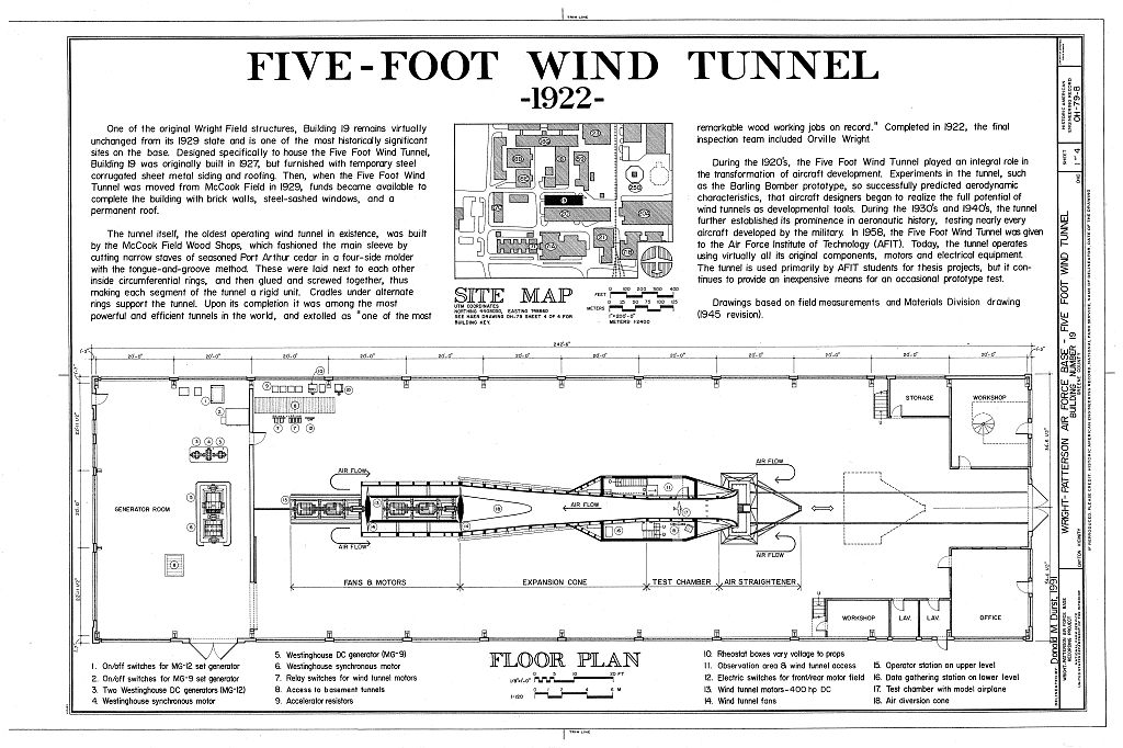
Other single doors are located on the north and east sides of the building. The original copper downspouts have been painted over, and several original awning hooks remain over the windows. The tunnel itself retains most of its original components. The motor generators, drive motors and electrical equipment are all original. This equipment (built by Sprague Electric between has only been overhauled once, and that was not until the early Four original humidifiers, manufactured by the Bannson Company, remain near the ceiling of the building. HISTORY: One of the original Wright Field structures, Building 19 remains virtually unchanged from its state and is one of the most historically significant buildings on Wright-Patterson Air Force Base.
Although designed specifically to house the Five-Foot Wind Tunnel, Building 19 was built in as a temporary structure, with steel corrugated sheet metal siding and roofing. When the Five-Foot Wind Tunnel was actually moved from McCook Field in funds became available to make the building permanent with brick walls, steel-sashed windows, and a permanent roof. The Air Service's Engineering Division began planning the construction of a wind tunnel after World War I.
Wind tunnels had been an increasingly popular tool for aircraft engineering since the Wright brothers successfully used data from their homemade tunnel (22"-square and 5'-long) in By subjecting small scale models to artificial winds, tunnels allow engineers to test the effect of design changes on such characteristics as airplane drag, stability and maneuverability at far lower cost than would the building of full-size prototype airplanes. By the Air Service was issuing outside contracts for aerodynamic testing in the amount of per year. The construction of an in-house wind tunnel seemed an economic and practical necessity. WRIGHT-PATTERSON AIR FORCE BASE, AREA B, BUILDING 19, FIVE-FOOT WIND TUNNEL HAER No.
OH-79-B (Page 3) Refinements to tunnel technology have been constant in this century, but engineers have identified five elements that constitute any wind tunnel: an enclosed passage through which a drive system sends moving air; a test section, in which a scale model is suspended in a controlled airstream; and associated test instrumentation. Originally, the Air Service Engineering Division desired an 8-foot diameter test section for its research at McCook Field. At the time, however, no building at McCook was large enough to contain a tunnel of that size. Moreover, since it was known that the tunnel might be moved in the near future, portability was a significant concern.
Consequently, the Army Air Service settled on a 5-foot version, with provisions for increasing the size at a later date. The McCook Field Wood Shops built the tunnel under the supervision of Myers, most probably without special design drawings or specifications. It is likely, however, that engineers at the Massachusetts Institute of Technology contributed the basic plans for the tunnel. Upon completion it was the most powerful and efficient tunnel in the world, and was extolled as a remarkable wood working job. When the tunnel was completed in the final inspection team included Orville Wright. The Wood Shops at McCook fashioned the tunnel's main chamber by cutting narrow staves of seasoned Port Arthur cedar in a four- side molder.
These were fitted together with the tongue-and- groove method inside circumferential rings, and then glued and screwed, thus making each segment of the tunnel a rigid unit. Cradles under alternate rings supported the tunnel. The cradles for the test section segments were mounted on wheels that rode on rails, which allowed the tunnel to accommodate tests of maximum range and make use of the two original model support systems, or balances. The tunnel's test section has employed three types of balances in its lifetime. It originally came equipped with a National Physics Laboratory mass balance (manufactured by Wm. Gaertner & Co. in Chicago), embedded in 8 feet of concrete. Although not used for many years, all the components survive.
The other original model support is the tunnel's wire balance (sometimes referred to as a "Wright balance"), which also remains in Building 19 and is still used periodically. The primary means of model support and data collection today is a string gauge balance which features a full 6 of freedom and--sacrificing sensitivity for quantity--can issue about 400 data points per second. Instrumentation used in the tunnel included a water and kerosene micrometer (original), which was very accurate in boundary layer testing, but very slow and tedious to operate; several manometers (used to measure the pressure of air around a WRIGHT-PATTERSON AIR FORCE BASE, AREA B, BUILDING 19, FIVE-FOOT WIND TUNNEL HAER No.
OH-79-B {Page 4) surface); and an inclinometer dating from the Air was driven through the experimental section by two fans of 900 horsepower each. Wind speeds could reach 260 miles per hour, although the usual test conditions involved winds of miles per hour. According to Harold Larsen, Professor Emeritus at the Air Force Institute of Technology and long-time operator of the Five-Foot Wind Tunnel, the fabrication of the two twelve- blade fans for the tunnel was delayed due to the difficulty of procuring wood of the proper hardness. Tunnel engineers did not find an adequate source for the wood until they learned of a frozen cherry orchard in Michigan. Sometime during the a model accidentally escaped the test section, flying through the fan section where it shattered one fan blade.
As a result, the damaged blade--as well as the one directly opposite it--had to be removed, leaving only ten blades on the front fan. Almost seventy years old, the fans have developed hairline cracks in their hubs. Consequently, Professor Larsen is currently designing replacement fans which will make use of a composite material and a new, more efficient design. One of the last pieces of equipment moved to the new installation at Wright Field, the tunnel was disassembled at McCook during February of and reassembled in Building 19 by February of the next year. The tunnel itself was unaltered, except for the addition of an experimental cabin built around the tunnel near the test section, and the removal of wheels from the support cradles.
Building 19 1 s floor does have permanent rails installed, but the straightening vane assembly (which directs air flow in the tunnel) is now the only maneuverable component of the wind tunnel. The straightening vane assembly and the straightening vanes in the fan section both consist of an even number of vanes arranged symmetrically. Aerodynamics engineers have since discovered that an asymmetrical arrangement of a prime number of vanes is more efficient. One of the first assignments for the new tunnel (while still at McCook Field) was to test models of the Barling Bomber of The tunnel provided critical data on performance and stability on what was at that time the world's largest airplane.
The highly successful tests demonstrated that a wind tunnel could save tremendous amounts of time and money by increasing the predictability of prototypes. At the time of the Barling Bomber project, a test represented about 1 percent of the total cost of a new experimental airplane. Consequently, if a proposed aircraft turned out to be of a faulty design, 99 percent of the project cost, and possibly the pilot's life, was saved. At Wright Field, the Five-Foot Wind Tunnel became a critical component in the development of aircraft technology. The tunnel WRIGHT-PATTERSON AIR FORCE BASE, AREA B, BUILDING 19, FIVE-FOOT WIND TUNNEL HAER No.
OH-79-B (Page 5) tested nearly every aircraft, both whole models and components, developed by the military during the The Five-Foot Wind Tunnel provided critical data on the problems of "flutter"--an instability of the aircraft which eventually leads to failure. Tunnel engineers conducted control surface flutter, flight flutter, and flutter model tests on many aircraft and components prior to World War II. In the Aircraft Lab created a Flutter and Vibration Section, which took over most flutter testing. They conducted most tests in flight, since wind-tunnel engineers were reluctant to test models which might break up and damage the tunnel. Nonetheless, the Five-Foot tunnel has retained its usefulness for other kinds of researches.
In the Aircraft Laboratory (predecessor of the Flight Dynamics Directorate of Wright Laboratory) gave the Five-Foot Wind Tunnel to the Air Force Institute of Technology for its students' thesis projects, which often concentrate on specific problems for which the Air Force needs data. Furthermore, the Aeromechanics Division still occasionally uses the tunnel for testing, such as recent work on the project. Since World War II, the long list of aircraft that have benefitted from the experiments in the Five- Foot Wind Tunnel include the EC-135 (ARIA), and numerous missile systems. The models used in wind tunnels can be extremely expensive and time-consuming to build, thus reducing a tunnel's efficiency by limiting the amount of work available for it.
For example, just prior to World War II, an aluminum wing model for an A-26, accurate to within 11 , cost However, in a dramatic cost-cutting move, Harold Larsen contacted the commercial model company Revel in the It turned out that their 59 cent plastic models were well within the accuracy tolerances needed to conduct stability, control and aerodynamic testing. Consequently, thousands of dollars could be saved on initial testing of particular prototypes. It was only when the testing relied on mass, or high loads that more expensive models were needed, since plastic deflects easily. Many of the models tested in the tunnel throughout its long history remain on display within the wind tunnel building.
Examples range from early triplanes to large-scale missile bodies and early space shuttle prototypes. The Five-Foot Wind Tunnel enjoys status as the oldest operating wind tunnel in existence anywhere, and is being considered for National Landmark status by the American Society of Mechanical Engineers. Although Wright Field has housed many other, newer wind tunnels, the Five-Foot tunnel still presents an inexpensive and quick means for preliminary testing. About 30 percent of the tunnel's work is for other organizations, such as WRIGHT-PATTERSON AIR FORCE BASE, AREA B, BUILDING 19, FIVE-FOOT WIND TUNNEL HAER No. OH-79-B (Page 6) the Army, Navy, Central Intelligence Agency, and private contractors--essentially anyone with a government contract can arrange a test in the tunnel.
In recent years, the tunnel has been the site for such diverse tests as skyscraper aerodynamics, soap box derby models, and bicycle wheels for the U.S. Olympic team. Building 19 is almost exclusively a housing for the Five- Foot Wind Tunnel, although a few support facilities are also in the building. Enclosed office and workshop spaces flank the large bay doors leading out the west end. The motor-generator room at the east end of the building also contains two smaller wind tunnels. One of the tunnels, powered by a air conditioning motor, is used for tests needing very low turbulence levels and produces airspeeds up to 70'/sec. The second, very small and unique, wind tunnel tests cascades and turning vanes. The building also contains a 2-ton overhead crane.
For bibliography, see Wright-Patterson Air Force Base overview report (HAER No. OH-79).
 Block
Block