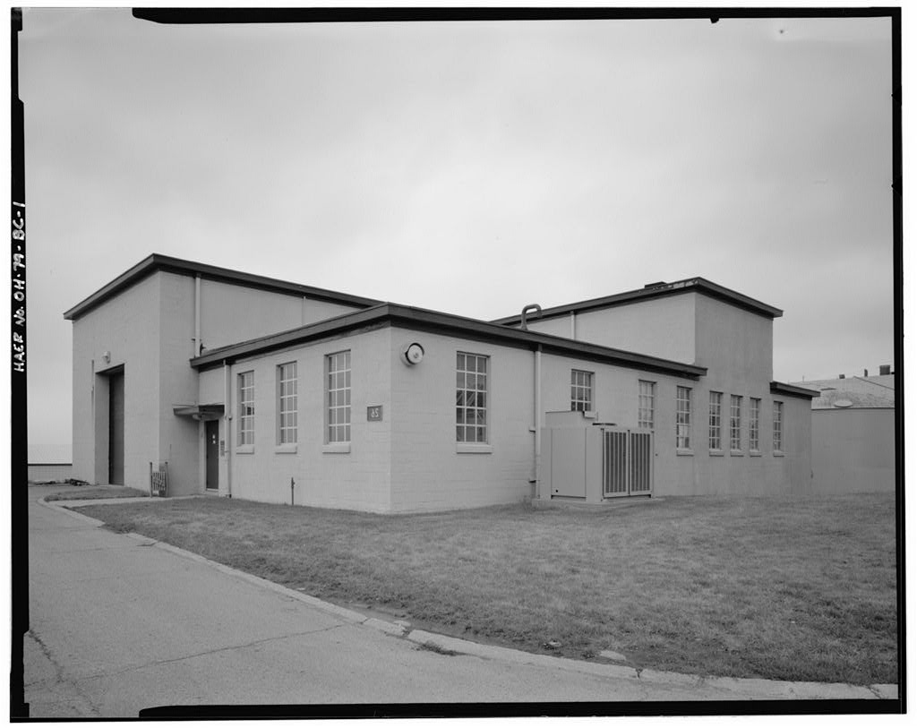
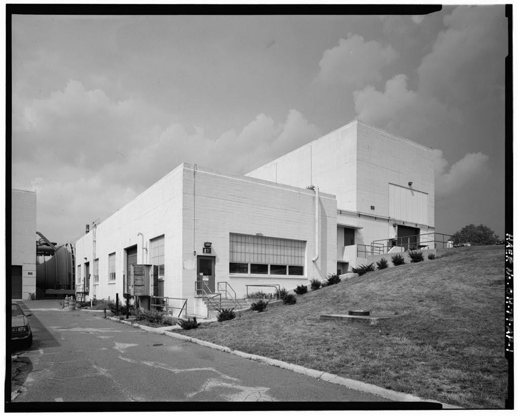
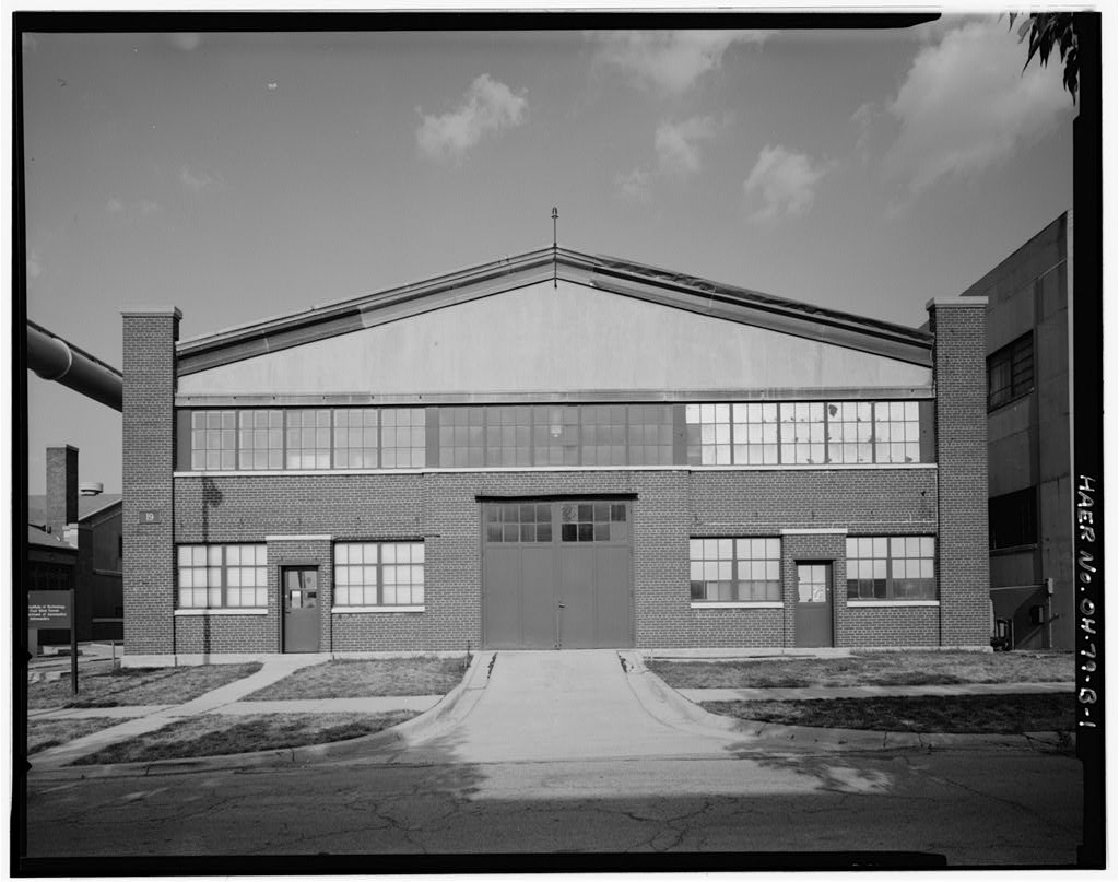
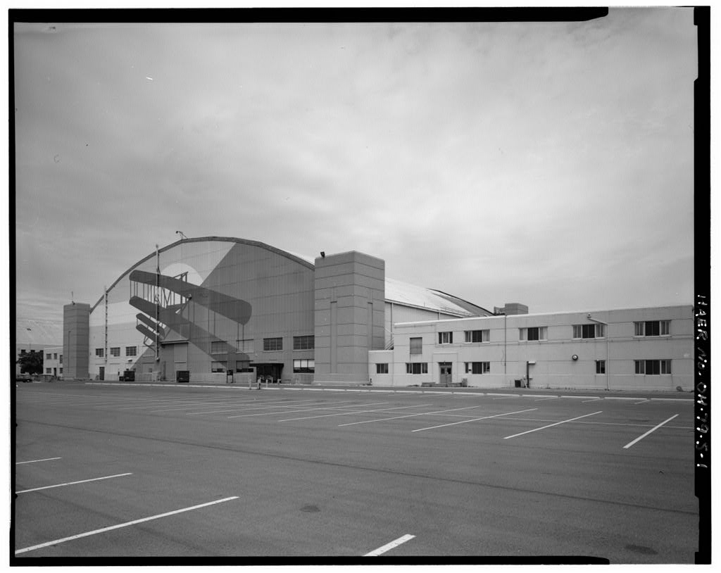
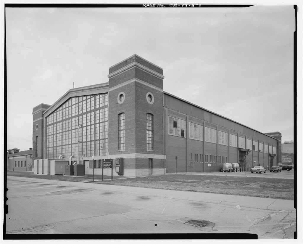
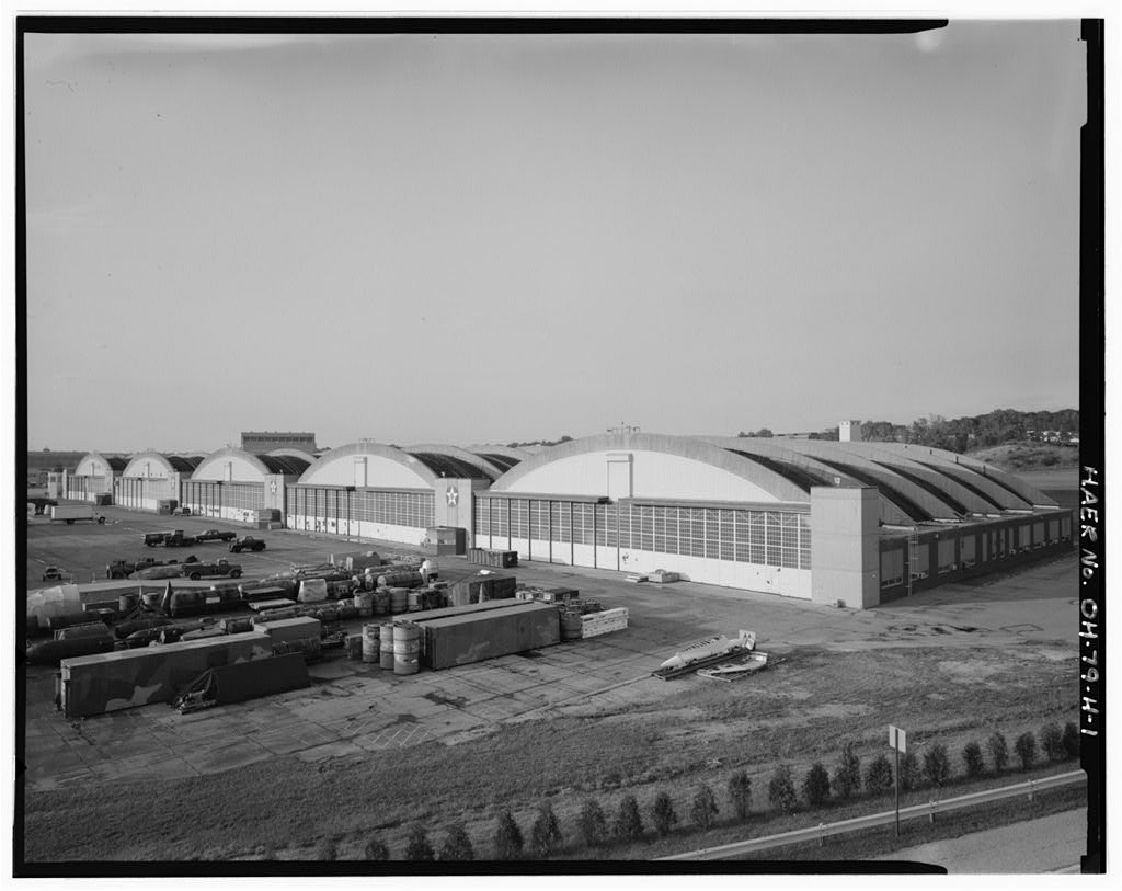
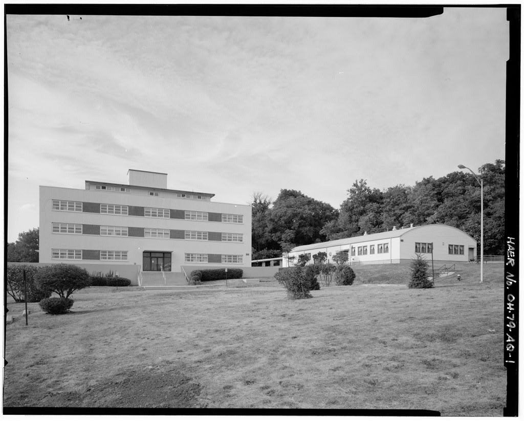
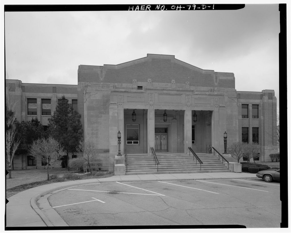
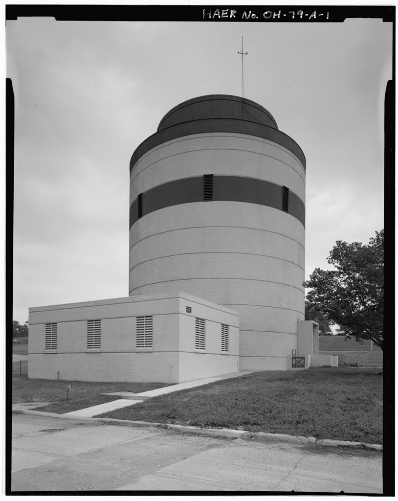
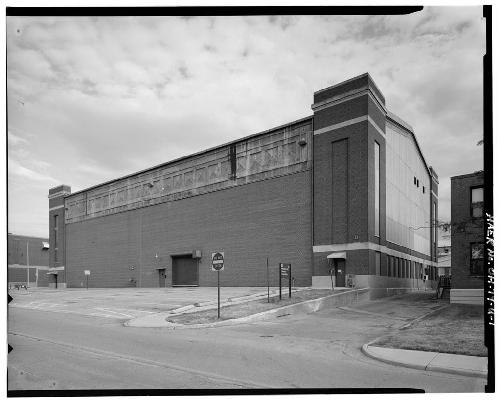
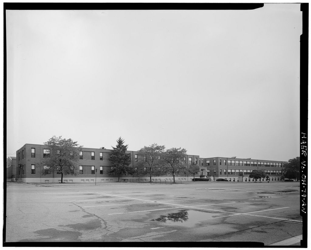
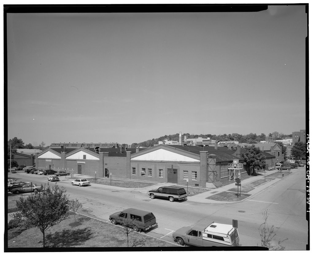
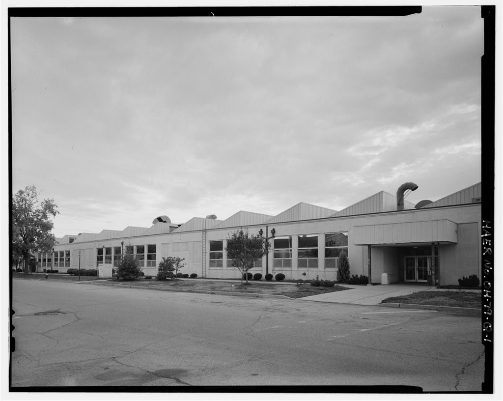
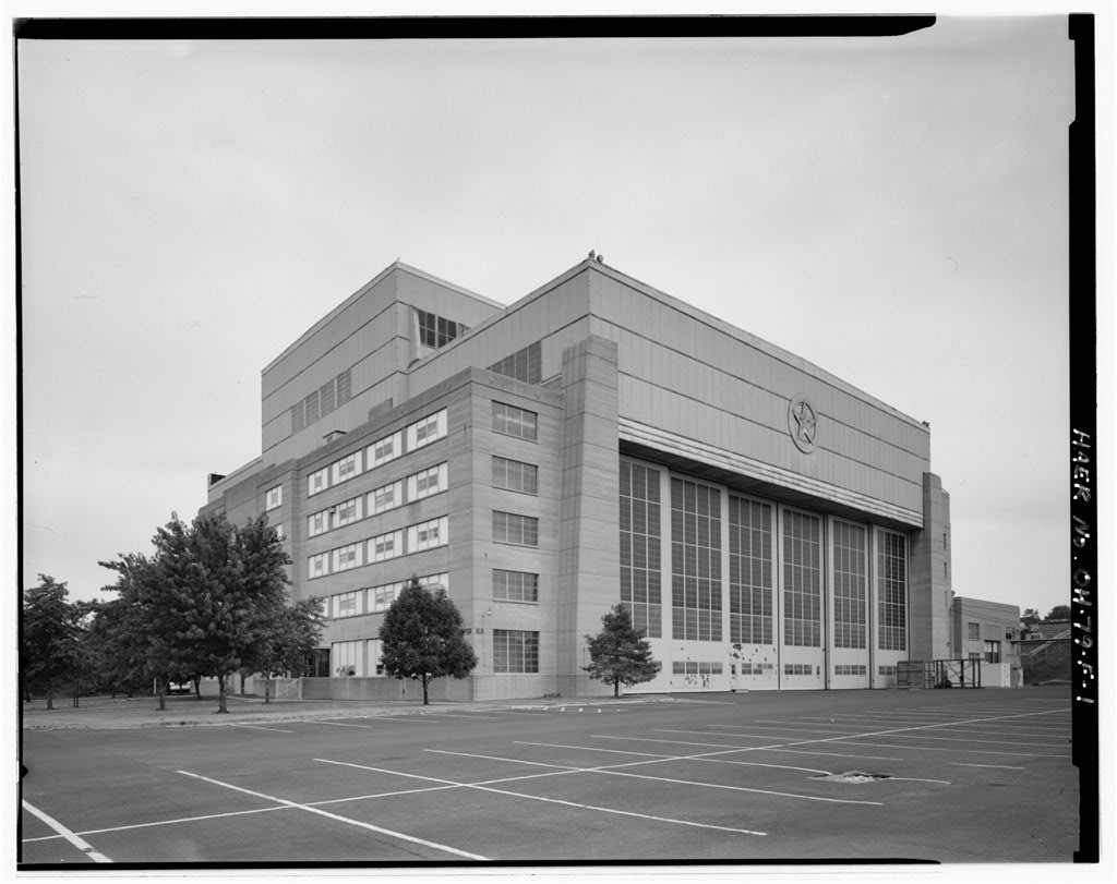
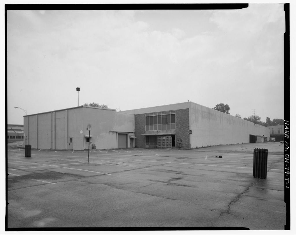
Building 26 sits in the northeast corner of the wind tunnel complex, and, although it is largely obscured by additions, tanks, fences and pipes, it is consistent in style with the other buildings in the vicinity. The three-story, split level, reinforced-concrete building has a flat roof with a wood cornice and frieze band, a penthouse, and irregular wings. The two-story west end has a parapeted roof front and four upper level window bays. The roof underside and the control room inside have been acoustically treated. HISTORY: In September of construction began on Building 26, the new Supersonic Testing Laboratory. By the Two Foot Supersonic Wind Tunnel was operational, with the Six-Inch Supersonic Wind Tunnel following a year later.
Two-Foot Trisonic Gasdynamics Facility The "trisonic" in this wind tunnel's name refers to its capability to operate at subsonic, transonic, and supersonic speeds. The tunnel operated for two decades as the Supersonic Gasdynamics Facility, capable of only supersonic and relatively inefficient subsonic testing. In the early 197 0s, however, a 15" transonic section was designed to fill the transonic void left by the conversion of the Ten-Foot Wind Tunnel to the 50 Megawatt Facility. For subsonic testing, this closed circuit, variable density wind tunnel generates airflow at mach speeds from to With the transonic insert in place, airflow through mach 1 can be attained.
For supersonic testing, different sets of nozzles are inserted for discrete mach numbers of and In the early the tunnel s compressor could be connected in series with the Ten-Foot Wind Tunnel's old scavenging pumps in Building which gave the tunnel a mach 5 capability. However, that configuration produced an airflow with a Reynolds Number too low for practical applications. (Reynolds Number is the ratio represented by dividing the product of the density of the fluid and the velocity of the fluid and the linear dimension of the body in the fluid by the kinematic coefficient of viscosity of the fluid.
Thus, as the size of the model decreases, the density of the fluid must increase proportionally for the test to accurately illustrate the aerodynamic properties of the full scale model in flight. This becomes an especially critical factor for high speed tunnels, as they usually have very small test sections and therefore are limited to very small scale models.) Powered by a 3500-horsepower induction motor and a horsepower AC synchronous motor, the ten stage, axial flow compressor features unique variable vanes. The stagnation section WRIGHT-PATTERSON AIR FORCE BASE, AREA B, BUILDING 26, SUPER SONIC TEST LABORATORY HAER No. OH-79-BC (Page 3) contains a honeycomb and screen arrangement to minimize turbulence.
This section also maintains the airflow's temperature at 100 F ( 1 ) with a water-cooled heat exchanger. Model support for the tunnel is a rack-mounted 50" radius crescent, equipped with a variety of sting extensions. The test section is equipped with Schlieren quality windows. The tunnel's optical instrumentation includes excellent Schlieren and laser light sheet capabilities, spherical and parabolic mirrors, optical benches, light sources, cameras, and an interferometer. A Jarrel Ash 3.4 meter grating spectrograph was transferred to Building 254 in the early Consuming eight million watts per hour, the Trisonic Gasdynamics Facility's continuous run-time makes it preferable to many other high temperature, high speed tunnels.
Throughout its 40 years of operation, the tunnel has contributed to many advanced aircraft and missile projects. High angle of attack studies are popular in the tunnel, which can simulate angles up to 48 . For example, numerous nozzle designs for the nose tip have been tested in the facility. The nozzles, which improve high angle of attack and tight turning capabilities, are also being considered for use on several of the advanced fighters currently in service and . Along with the numerous other hypersonic glide vehicles (some of which are not expected to be in production until and beyond) have been tested in the Trisonic Gasdynamics Facility.
Some other designs recently analyzed in the tunnel include submerged inlets for aircraft and missiles, a Canadian delta wing model, and ICBM nose tips capable of penetrating 50' of concrete. Six-Inch Supersonic Wind Tunnel Built in the Six-Inch Supersonic Wind Tunnel facility conducted aerodynamic testing on models in the supersonic range by Powered by one 1, 000-horsepower variable-frequency motor, the variable-density, closed-return wind tunnel had mach capabilities to with a test section measuring 6" x 6" x However, by the mid the tunnel, though not officially closed, was no longer being used.
With no foreseeable use, the Air Force donated the Six-Inch Wind Tunnel to Ohio State University in For bibliography, see Wright-Patterson Air Force Base overview report WRIGHT-PATTERSON AIR FORCE BASE, AREA B, BUILDING 26, SUPER SONIC TEST LABORATORY HAER No. OH-79-BC (Page 4) Two Foot Trisonic Gasdvnamics Facility Type: Closed circuit, variable density, continuous flow Overall Size: 71 3" x 27' Centerline Circuit Length: Model Type: 3 dimensional Test Section: Closed throat, rectangular, 2' x 2', 4' long Max. Diameter: 9' Contraction Ratio: Velocity: Subsonic: mach - Transonic: through mach 1 Supersonic: discrete mach no. 3.0 Max. Dynamic Pressure: Subsonic: 350 psf Transonic: psf Supersonic: 600 - psf Total Pressure: psf (normal range: Max.
Reynolds Number/Foot: Subsonic: 2.5 million Transonic: 8 million Supersonic: 3-5 million Power: hp induction motor, hp AC synchronous motor Temp. Control: Water cooled (calcium chloride brine heat exchanger) Operating Temp. & Press. Range: Tunnel stagnation temperature maintained at 100 F 1 , stagnation pressure maintained to within 1 psf of any pressure within range Air Drive: Allis Chalmers 10-stage, axial flow compressor Drive Shaft: 10' long. WRIGHT-PATTERSON AIR FORCE BASE, AREA B, BUILDING 26, SUPER SONIC TEST LABORATORY HAER No. OH-79-BC (Page 5) Max. Fan Model Support System: Rack mounted 50" radius crescent with position displayed on operator's console with any accuracy to F, pitch range from -1 F to F (-1 to F for transonic section)
 Block
Block