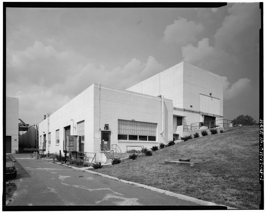
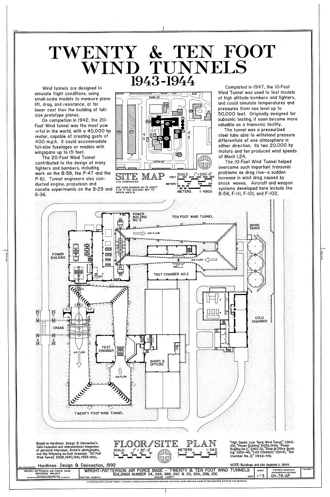
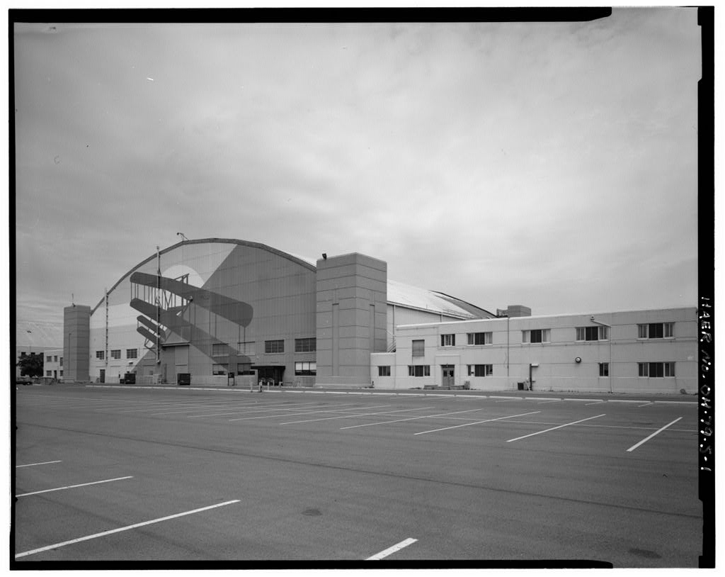
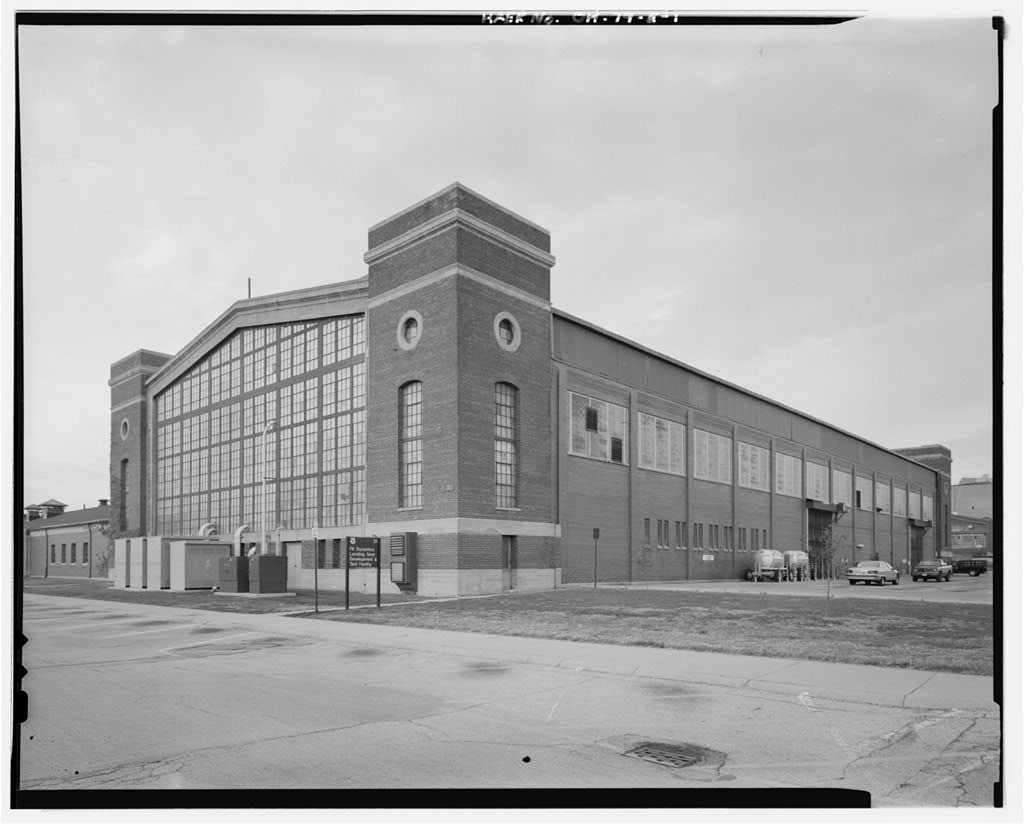
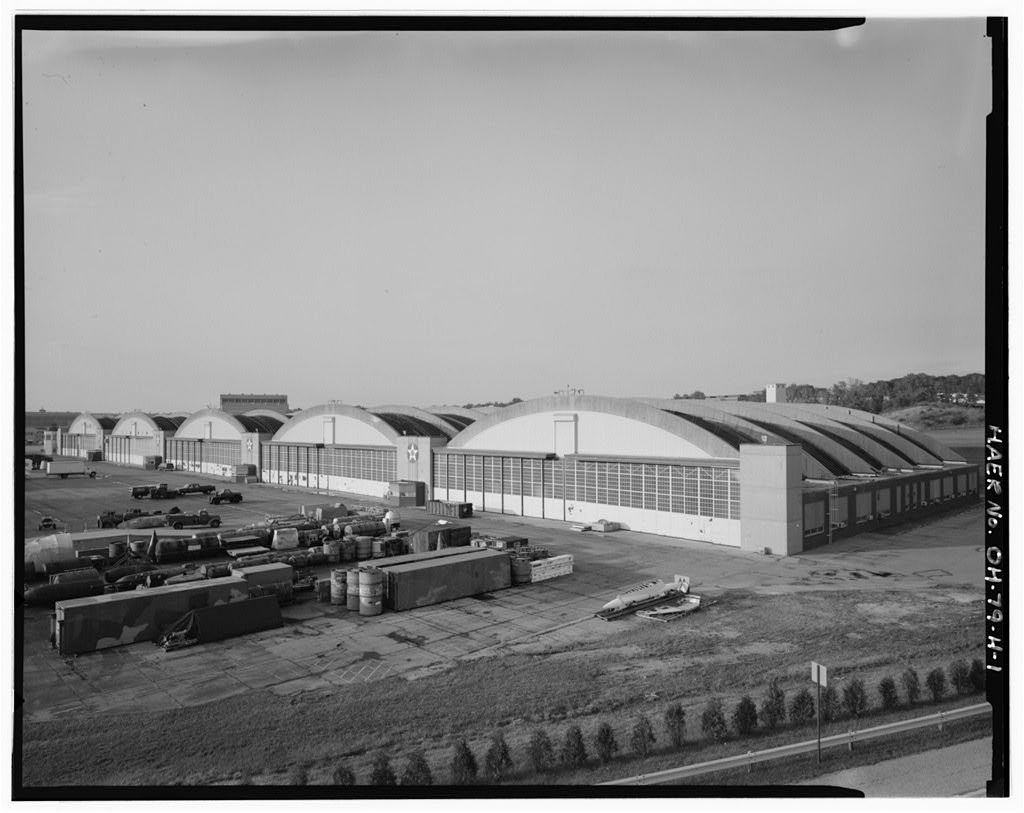
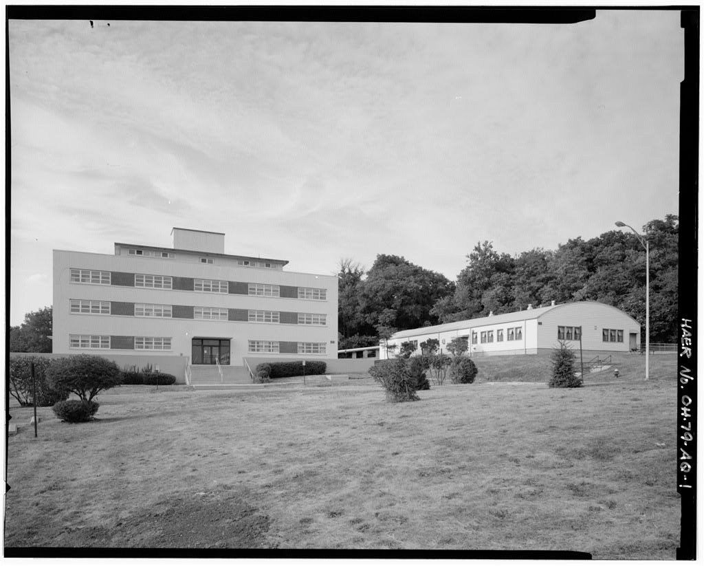
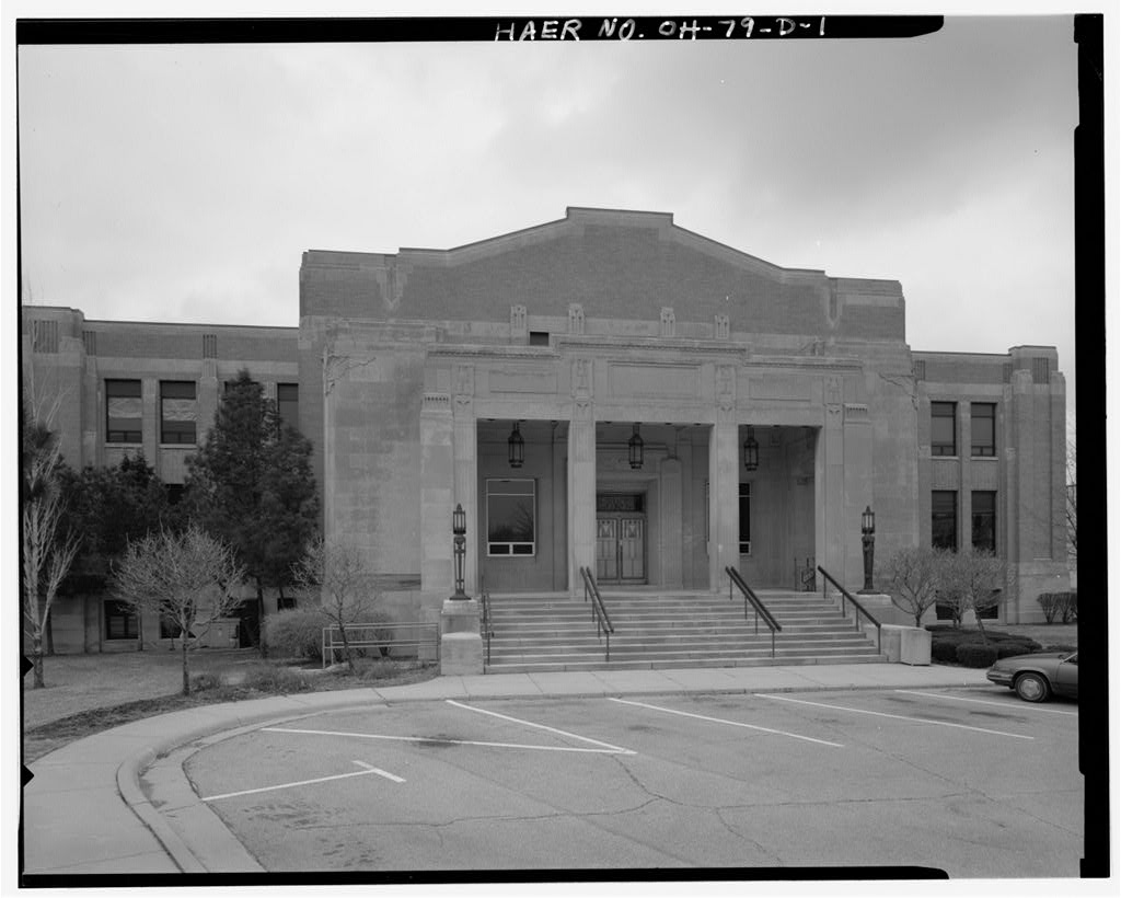
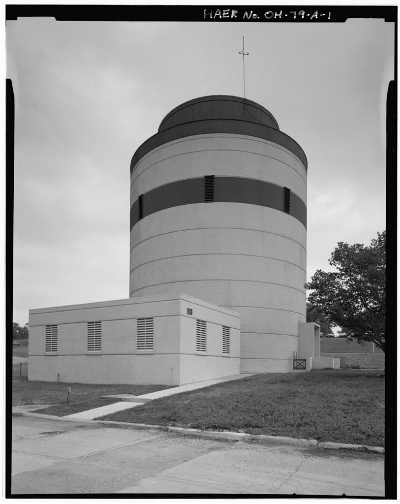
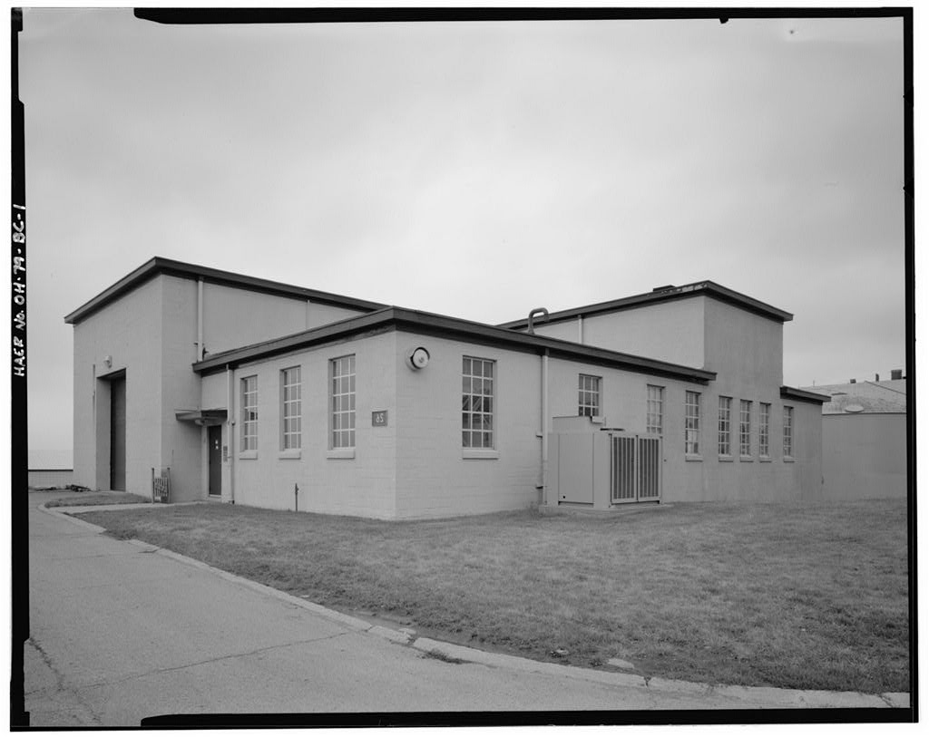
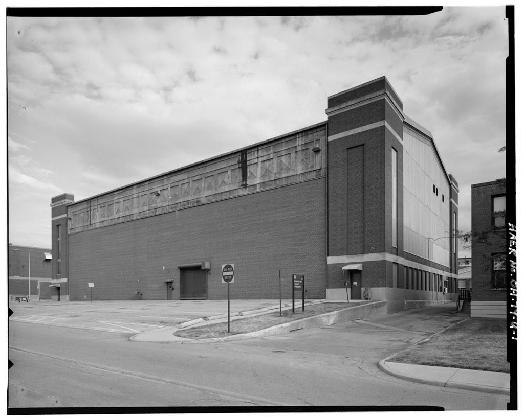
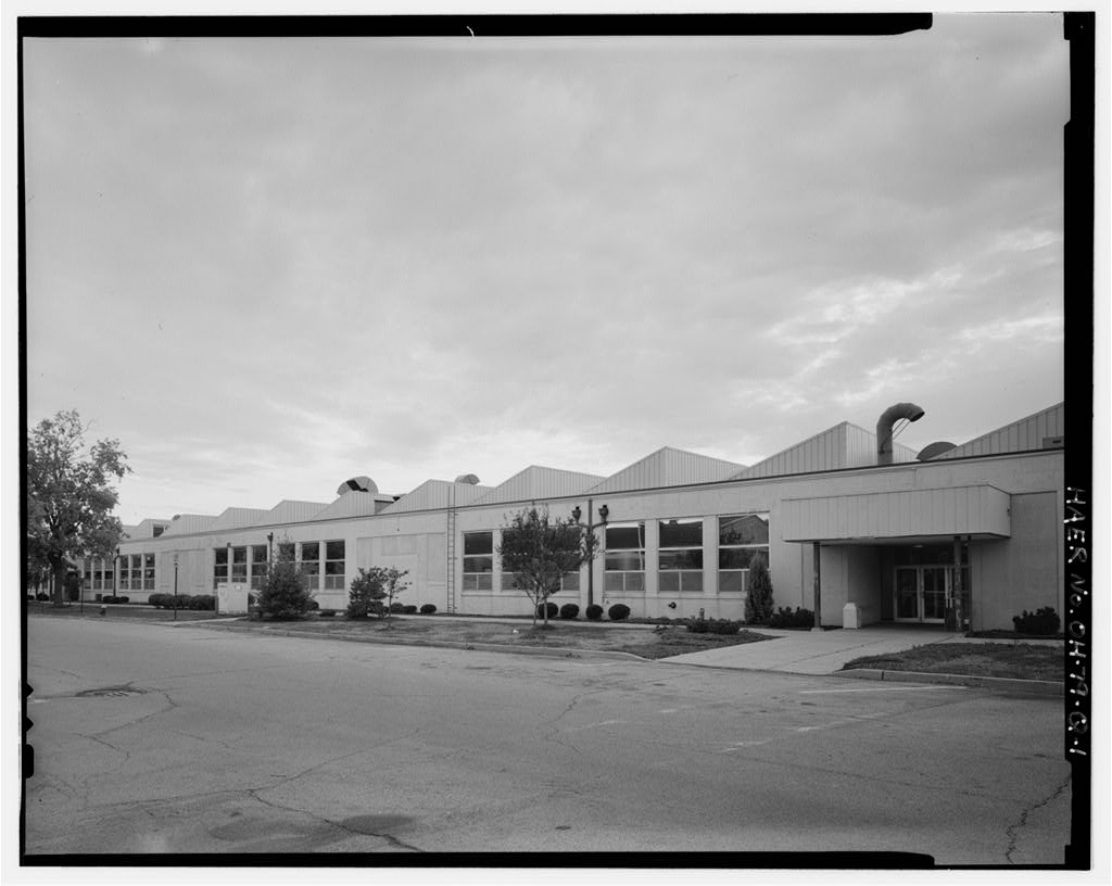
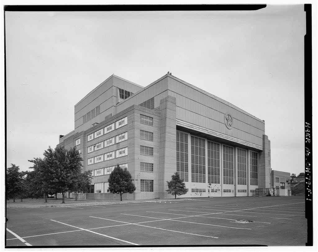
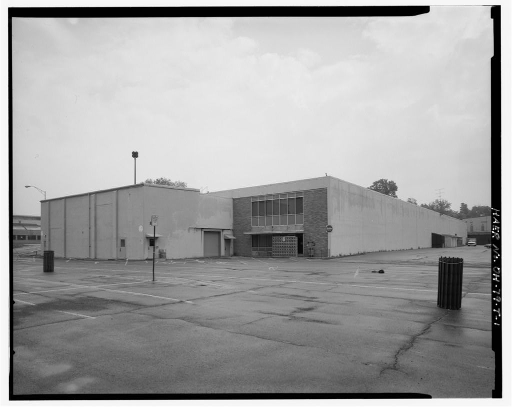
Building 25A: Cold Chamber Building 2 5A is a four-story, split level, concrete building, originally L-shaped with one wing 62* x and the other 60' x Additions were made in and during which the lower section was extended to the south. Building Test Chamber Building Building 25B is a four-story, high-bay, cast-in-place concrete building. The tunnel portion of the 10-Foot Wind Tunnel is still in place, running through the building from west to east. The conversion in the to the 50 Megawatt Facility did not alter the building significantly, except for the new hardware inside the tunnel structure and its related equipment. One of the 10-Foot Wind Tunnel's original 20,000-horsepower motors sits idle against the south wall.
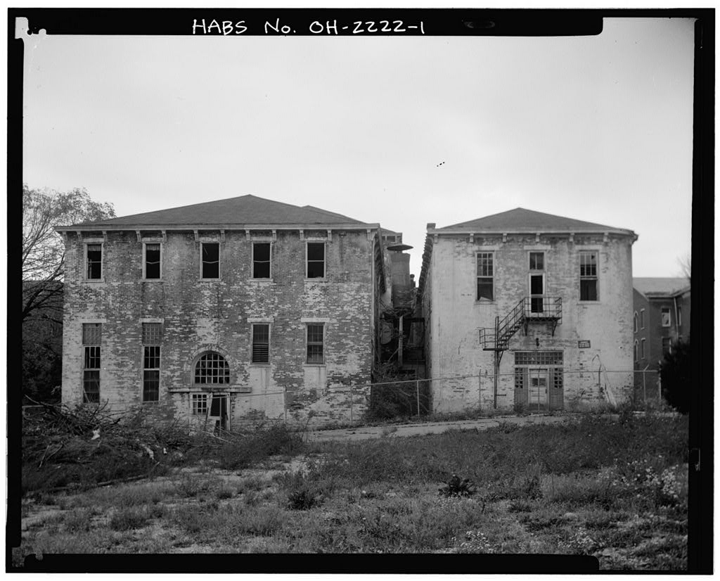
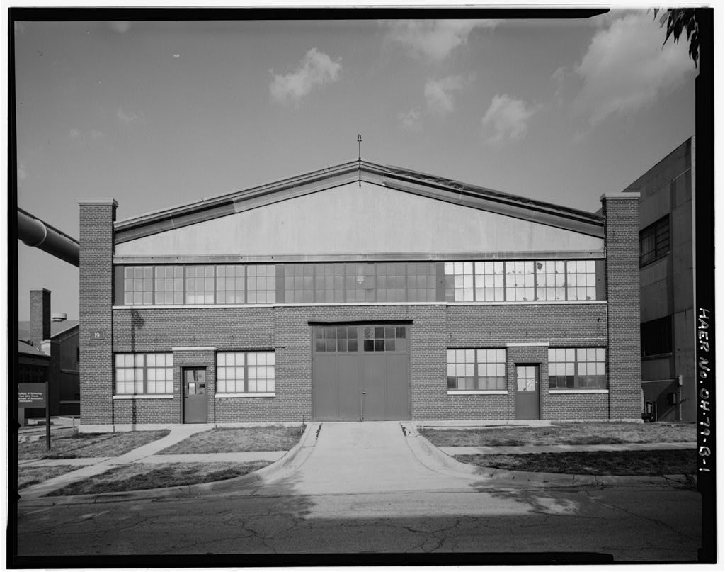
Building Subsonic Aerodynamic Research Facility The three-story, open bay building features six-course brick, a high concrete foundation and a parapeted concrete coped flat roof. The north end of the building has screen-covered blow-out panels over its entire expanse. Buildings 25C and 24A have nearly identical pilaster and window bay arrangements, both displaying elements of the Georgian style. The buildings are now connected by a one-story, flat roofed addition. Building 2 5D: Scavenging Building Building 25D is a two-story brick building, with a low- parapeted flat roof with concrete coping. It has steel-sashed windows with concrete sills.
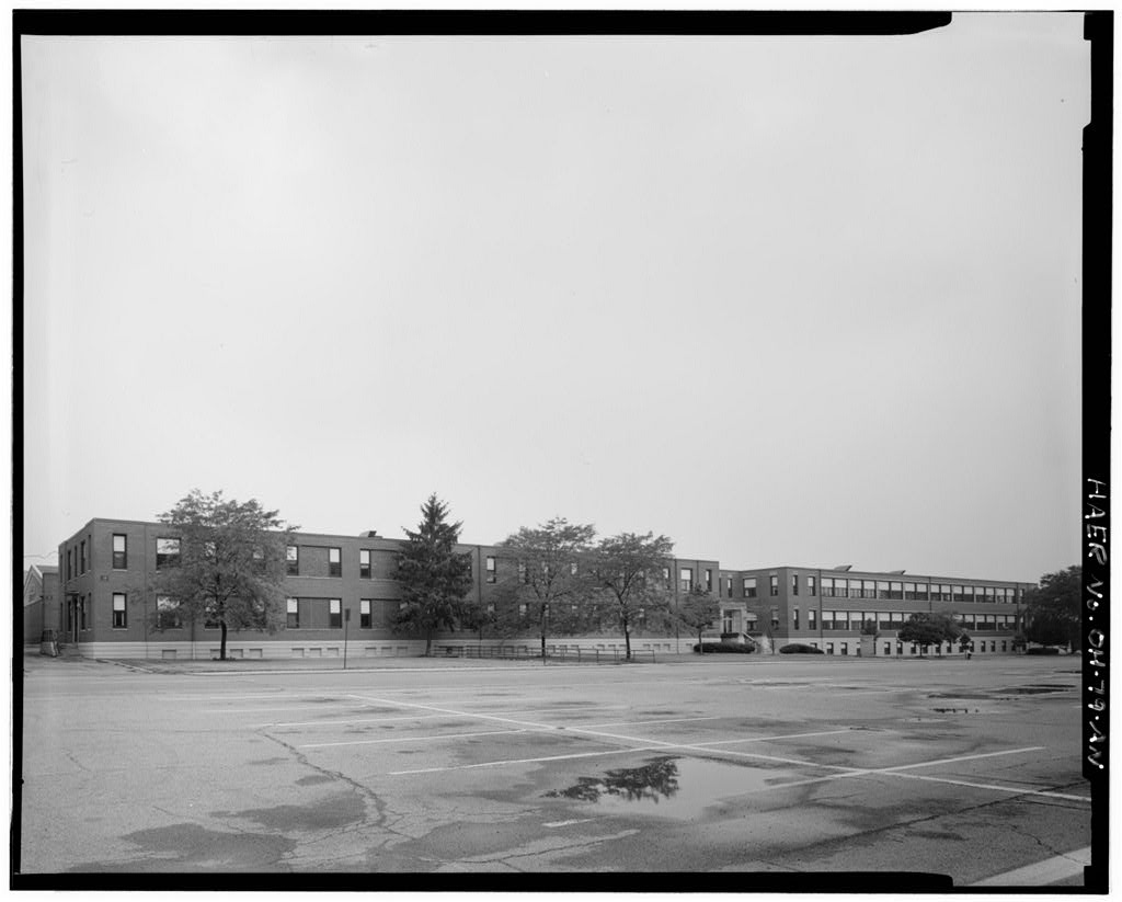
The north side has flat soldier arches on the three long window bays, while the south side abuts Building Among the equipment currently in Building 25D is a set of auxiliary motors and a two-stage compressor previously used for the 10-Foot Wind Tunnel. Not presently in use, the set may be employed in the future for auxiliary airflow to the Subsonic Aerodynamic Research Laboratory (SARL), for miscellaneous secondary flows such as experiments requiring simulation of cabin explosions or jet exhaust. Also in the 50' high building is a 25-ton bridge crane, a control room, and an auxiliary compressor system. WRIGHT-PATTERSON AIR FORCE BASE, AREA B, BUILDINGS 25A-D & 24A-C, 10-FOOT & 20-FOOT WIND TUNNEL COMPLEX HAER No.
OH-79-AP (Page 3) HISTORY: Building 25A: Cold Chamber Completed in the Cold Chamber was designed by J. Gordon Turnbull, Inc., of Cleveland, Ohio, with consulting engineers Svedrup & Parcel, of St Louis. Frank Messer & Sons, Inc., of Cincinnati, was the contractor. The building was originally known as the Frigitorium and belonged to the Aeronautical Accessories Laboratory. It contained cold chambers which used four gallon brine tanks to attain temperatures as low as -75 F for arctic testing. The cold chambers no longer exist. Among the facilities now housed in Building 25A is the 2-Foot Hydrodynamic Facility, a water tunnel that, while not as precise as a wind tunnel, provides a reasonably accurate, qualitative simulation of an aircraft in flight.
Finally, Building 2 5A holds auxiliary equipment for the Trisonic Gasdynamic Facility (see Building and the 50 Megawatt Electrogasdynamic (see Building Cold Chamber System Cold Room Dimension: 82f x 25' x 25' Insulation: 14" corkboard Cold Room Air Circulation: ft3/min. , two 30 hp fans Cold Cells 59 x 11' x 18 Insulation: 6" Ferrotherm (13 layers) Refrigeration Temperature: -75 F Refrigeration Capacity: BTU/hr net Compressors: 5 Ammonia Total Horsepower: 500 Ammonia Pumps 4 5 5 hp each Water Pump: 360 15 hp Exciter: 300 amp, 250 v, 100 hp Building Test Chamber Building Built in Building 25B contained the test section and control room for the 10-Foot Wind Tunnel.
The 21,738-square-foot building also housed office space, a crew room, a model room, and two traveling overhead cranes (40-ton and 5-ton). Designed for testing models of high altitude bombers and fighters, this closed circuit tunnel was originally intended for high speed subsonic testing, but soon became more valuable as a transonic facility. Unlike the 20-Foot Wind Tunnel nearby, the 10- Foot tunnel could simulate the temperatures and pressures associated with flight from sea level up to altitudes of WRIGHT-PATTERSON AIR FORCE BASE, AREA B, BUILDINGS 25A-D & 24A-C, 10-FOOT & 20-FOOT WIND TUNNEL COMPLEX HAER NO.
OH-79-AP (Page 4) Construction on the tunnel began in March it was operational by January Laid out in a x rectangle, the tunnel exited the east side of Building 25B where it reached its maximum diameter of 40* and gradually narrowed before entering Building In this building the two 20,000-horsepower motors and fan section drove the air up to a speed of Mach The tunnel then returned to the west end of Building where its test section, control room and related equipment resided, for a centerline circuit length of and a total volume of cubic feet. The tunnel itself was a pressure-sealed steel tube built to withstand pressure differentials of 1 atmosphere in either direction.
Approximately 70 percent of the tunnel's research time went to missile and aircraft models, while the remaining 3 0 percent was spent on wings and other components. Many special conditions arise in the transition from subsonic to transonic speeds. In the days before computer analysis, the nonlinear equations needed to explain these special aerodynamic circumstances were not practical. The 10- Foot Wind Tunnel, therefore, was instrumental in solving many of the transonic problems. Dr. Bernhard Goerthert, a leader in transonic research for Germany during World War II, came to Wright Field in the late through Project Paperclip.
Under his direction, the 10-Foot Wind Tunnel helped overcome many important transonic obstacles, such as drag rise a sudden increase in wing drag when Shockwaves occur. Throughout the the tunnel's research was instrumental in the development of many aircraft and weapon systems, such as the Bomarc, Snark, Rascal, Matador, Navaho and the A4 heat-seeker. In 19 58 the 10-Foot Wind Tunnel was shut down to make room for the 50 Megawatt Electrogasdynamic Facility for study of the conditions experienced by hypersonic aircraft upon re-entry into the earth's atmosphere. Components are tested in an airflow that is heated by a powerful continuous electric arc.
Building Subsonic Aerodynamic Research Facility Built in this building originally contained the motors and fan section of the 10-Foot Wind Tunnel. The motors and fans were removed upon conversion to the 50 Megawatt Facility; the tunnel remained. With the demise of the 50-Megawatt Facility, the tunnel section was removed and the tunnel openings sealed to make room for the new Subsonic Aerodynamic Research Laboratory (SARL), which dominates both the interior and exterior of Building The tunnel's inlet takes up the north wall of the three-story building and the tunnel extends through the middle of the open bay building and out the south end. The tunnel's outlet extends out of the WRIGHT-PATTERSON AIR FORCE BASE, AREA B, BUILDINGS 25A-D & 24A-C, 10-FOOT & 20-FOOT WIND TUNNEL COMPLEX HAER No.
OH-79-AP (Page 5) building's south end, where a two-story structure has been built to house the tunnel's 20,OOO-horsepower motor and support the exhaust deflector shields. Building Scavenging Building Built in as the Scavenging Building to evacuate the 10- Foot Wind Tunnel, Building 25D held a set of motors and compressors, including two 4-stage centrifugal compressors driven by a horsepower motor. Today the structure houses the Environmental Control Systems Simulators. 10-Foot Wind Tunnel Type: Single Return Overall Size: 6" x Centerline Circuit Length: Model Type: 2 or 3 dimensional Test Section: 10* diameter, 18' 3" long, circular, closed throat Max. Diameter: 40* Contraction Ratio: 16 to 1 Max. Velocity: Mach Max.
Dynamic Pressure: psf Power: Two hp AC induction motors using 20f Wind Tunnel speed control system Energy Ratio: Temp. Control: Calcium Chloride brine heat exchanger Operating Temp. & Press. Range: -30 to F (stagnation), to 2 atmospheres (stagnation) WRIGHT-PATTERSON AIR FORCE BASE, AREA B, BUILDINGS 25A-D & 24A-C, 10-FOOT & 20-FOOT WIND TUNNEL COMPLEX HAER No. OH-79-AP (Page 6) Air Drive: Four counter-rotating 19' diameter fans, 16 laminated spruce blades per fan, 11' diameter hub Drive Shaft: Two 42' long, 18" diameter solid steel shafts Max.
Fan 465 Model Support System: Orthogonal balance (Wing through support system; Semi-span support system; or 3 strut support system); Rear sting support (with or without strain gage balance) Balance Capacity and Range: Orthogonal Balance Capacity: Lift Drag Side Force Rolling Mom. Yawing Mom. Yaw 5 Pitch -15 to +20 Pitching Mom. Strain Gage Balance Capacity: Lift 350 Drag Side Force Rolling Mom. Yawing Mom. lbs Pitching Mom. lbs Pitch or Yaw -3 to +8 Freon Refrigeration System for 10-Foot Wind Tunnel Refrigeration capacity: tons @ 70 F, 280 tons 40 F Refrigerant Temperature, Primary: -60 F Refrigerant Temperature, Secondary: -40 F Brine Tank Capacity galIons each WRIGHT-PATTERSON AIR FORCE BASE, AREA B, BUILDINGS 25A-D & 24A-C, 10-FOOT & 20-FOOT WIND TUNNEL COMPLEX HAER No.
0H-79-AP (Page 7) Total Brine Storage: gallons Total Refrigeration Storage: BTU Brine Range:-4 0 F to +12 0 F Brine Circulated Through Cooler:2500 gpm hp pump) Brine Circulated Through Tunnel Heat Exchanger:7500 gpm hp pump) Number of Compressors:2 Centrifugal Total Horsepower: Speed Range: to Condenser Water Tower: gpm Water Tower Fans: Two 3 0 hp Water Pump: gpm (75 hp) Water Pump: gpm (40 hp) Heat Exchanger (Wind Tunnel): ft2 Building 24, 20-Foot Wind Tunnel Complex Buildincr 24A: Power Building for Wind Tunnel Complex Building 24A is a three-story building featuring six-course brick, a high concrete foundation and a parapeted, concrete-coped, flat roof.
On the east and west sides of the building, eight window bays are arranged two-four-two, with three-quarter rectangular pilasters between the sets and at the ends of the building. The window bays feature long, narrow windows at the second level, and shorter windows on the lower and upper levels. An addition connecting the building to Building 25C has eliminated the lower level window bays on the east side. The north entrance has double metal doors flanked by six over six steel-sashed windows. Above the doors, beginning half way up the building, three narrow window bays extend to the top level. To the south of the building, a large craneway allowed for the installation and removal of the fan assembly. It still overlooks the complex, but is no longer operable.
The building contains two motor generator sets, a horsepower induction motor, and a 75-ton overhead crane. A second level balcony at the south end of the building houses the control room for the motors and motor-generator sets, and directly below are the control panels for the facility's electrical distribution system. WRIGHT-PATTERSON AIR FORCE BASE, AREA B, BUILDINGS 25A-D & 24A-C, 10-FOOT & 20-FOOT WIND TUNNEL COMPLEX HAER NO. OH-79-AP (Page 8) Building Sonic Fatigue Facility Support Area Building 24B was the original test chamber for the 20-Foot Wind Tunnel. This four-story, rectangular, concrete building has a low-parapeted flat roof. The wind tunnel openings on the north and south sides are now cemented over.
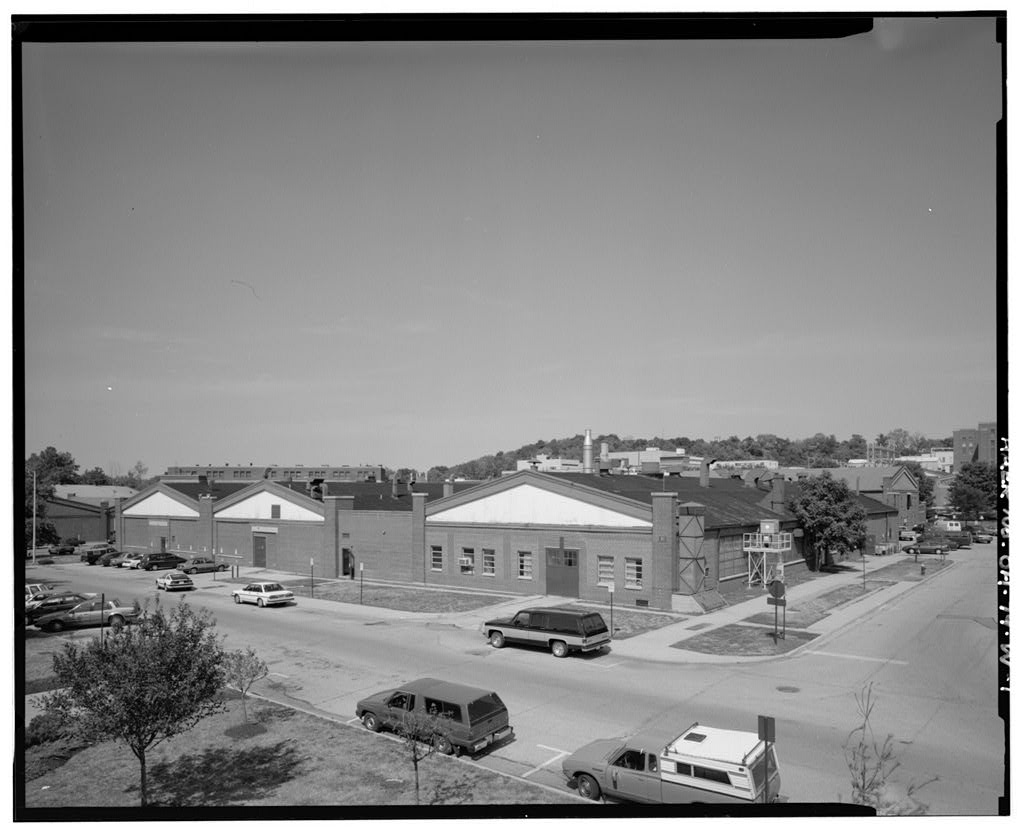
Building 24C abuts the east side, while the west side features concrete pilasters and twenty- four vent-like windows. Building 2 4C: Shop and Engineering Building This one-story shop and office building also has a parapeted flat roof. On the south facing end are doors flanked by two tall window bays with concrete sills. The east-facing mid section consists of two stories with a penthouse. There are eight large window bays on the southeast side. The advancing two-story entrance has windows on the penthouse and top level with two brick millions. The aluminum double doors have a concrete lintel and are flanked by two rectangular brick pilasters and ribbon windows.
HISTORY: Best known for the 2 0-Foot or Massie Memorial Wind Tunnel that it originally supported, the Building 24 complex comprises buildings dating from Structures from the World War II era were the first in what is now called the Aeromechanics Research Complex, a one-block area which includes, or included, the 20-Foot and 10-Foot Wind Tunnels, the Vertical Wind Tunnel, the Subsonic Aerodynamic Research Laboratory, the 2-Foot Trisonic Gasdynamic Facility, the 2-Foot Hydrodynamic Facility, the 6-Inch Supersonic Wind Tunnel, the 50 Megawatt Facility, and the Sonic Fatigue Facility. 2 0-Foot Wind Tunnel In the late 19 3 0s, physicist Dr. Theodore Von Karman was commissioned by the Army Air Forces to design the multi-million dollar 20-Foot Wind Tunnel. Captain Louis E.
Massie, the first chief of the Wind Tunnel Branch, oversaw its planning, design and construction. Tragically, in when the tunnel was 90 percent complete, Captain Massie died in a P-3 6 plane crash. At its formal dedication in the tunnel was christened the Massie Memorial Wind Tunnel. The new wind tunnel was, as one of many contemporary magazine reports put it, "truly colossal." The 20-Foot Wind Tunnel's horsepower motor was the largest variable-speed, wound-rotor-type induction motor of its time, making the tunnel the most powerful large tunnel in the world the previous most powerful wind tunnel only had two 4,000-horsepower motors. The tunnel utilized a WRIGHT-PATTERSON AIR FORCE BASE, AREA B, BUILDINGS 25A-D & 24A-C, 10-FOOT & 20-FOOT WIND TUNNEL COMPLEX HAER No.
OH-79-AP (Page 9) modified Kramer system to regulate the speed of the motor, and thus the fans and airspeed. Two motor-generator sets worked together to govern the main motor's rotor. When operating at full capacity, the two sixteen-blade fans approached 300 rpm while driving air through the circuit at 450 In an era where hypersonic tunnels in the mach range are almost common place, 450 mph may sound rather primitive but, considering the enormous test section, the tunnel was impressive even by today's standards. To regulate the heat generated by the 40' fans, a section just prior to the fans exchanged approximately 30 percent of the tunnel airflow with ambient air.
The 20' diameter test section accommodated full scale missiles or large scale models up to 16' long with a 15' wing span mounted on a six-component external balance. Models were installed and adjusted using a 10-ton elevator below the test section. The testing instruments themselves were housed in a 68'-high, reinforced-concrete building, in which technicians could observe and calibrate the behavior of models inside the tunnel. Completed in the 20-Foot Wind Tunnel contributed to the design of many World War II fighters and bombers, including considerable work on the Throughout its two decades of aeronautical experimentation, the 20-Foot Wind Tunnel contributed to countless aircraft and missile designs, including the P- 61, and McDonnel Convertiplane.
Tunnel personnel also handled engine, nacelle, and propulsion experiments for such aircraft as the and Occasionally, the tunnel was used to conduct experiments on fire suppression systems. An was once mounted in the tunnel and bullets fired into its burners to test the plane's combat effectiveness. The versatility of a tunnel with such a large test section was demonstrated when it was used for tests on a German V-l rocket smuggled out of Europe. Ordinarily, however, tunnel personnel conducted one of four types of experimentation: force and moment tests on models; pressure distribution and wake surveys; engine cooling studies; and powered model tests.
Powered and unpowered models accounted for approximately 70 percent of the tunnel's time, while wings, parachutes, and aircraft components each accounted for 10 percent. As aircraft began to exceed the speed of sound, the tunnel's effectiveness diminished. The need for subsonic research did not disappear, as even hypersonic vehicles must take off and land at subsonic speeds, but this type of testing could be done by NASA and even private industry. Consequently, the 20-Foot Wind Tunnel was deactivated on April 1, and the tunnel structure itself, WRIGHT-PATTERSON AIR FORCE BASE, AREA B, BUILDINGS 25A-D & 24A-C, 10-FOOT & 20-FOOT WIND TUNNEL COMPLEX HAER NO.
OH-79-AP (Page 10) which had dominated the area for almost two decades, was razed in Building 24A: Power Building for Wind Tunnel Complex Built as the power building for the 20-Foot Wind Tunnel, Building 24A has changed very little in fifty years. Equipment in the building could power either the 20-Foot Wind Tunnel or the 10- Foot Wind Tunnel (built in and now supplies power for the Structural Dynamics Facility (originally called the Sonic Fatigue Facility) and the Subsonic Aerodynamic Research Laboratory. The drive shaft from the Building's 40,000-horsepower motor extends from the south end to Building where it drove the compressor for the Sonic Fatigue Facility during the The compressor, the largest one of its time, provided high volume airflow to a bank of large noise generators.
These hydraulically operated sirens could generate noise level up to 170 decibel for the structural testing of aircraft components. Building Sonic Fatigue Facility Support Area Primarily the test section area for the 20-Foot Wind Tunnel, Building 2 4B also features a control room and support equipment for the tunnel. Two air locks provided access to the area containing the test chamber. Both air locks remain, although one has been converted into a telephone booth, and all the doors have been replaced. A 20-ton crane allowed for the installation of models, heavy equipment and the closed throat section. A 10-ton elevator beneath the test section served as a working platform for model adjustments. The platform and elevator equipment are intact, although not operable.
The facility also included a scale model of the tunnel powered by a 100-horsepower motor. The building is currently a support area for the Sonic Fatigue Facility, and includes two test chambers and a large butler building. The butler building fills most of the open area vacated by the 2 0-Foot Wind Tunnel's test section, and contains experiments on structures for use in space. Building Shop and Engineering Building Built as a shop and office area for the 20-Foot Wind Tunnel, the building still functions as a machine shop and office space for the Flight Dynamics Directorate. The construction contractor for this building was the Simpson Construction Company. For bibliography, see Wright-Patterson Air Force Base overview report (HAER No. OH-79).
WRIGHT-PATTERSON AIR FORCE BASE, AREA B, BUILDINGS 25A-D & 24A-C, 10-FOOT & 20-FOOT WIND TUNNEL COMPLEX HAER No. OH-79-AP (Page 11) 20-Foot Massie Memorial Wind Tunnel Type: Single Return Overall Size: x Centerline Circuit Length: 6" Model Type: 2 or 3 dimensional Test Section: Circular, 20' diameter, long, open or closed throat Max. Diameter: 45" Contraction Ratio: to 1 Max. Velocity: 450 mph empty (mach , 400 mph average model Max. Dynamic Pressure: 425 psf empty, 375 psf average model Power: hp AC induction motor, modified Kramer speed control system Energy Ratio: 4.9 Temp. Control: Air exchanger Operating Temp. & Press. Range: Atmospheric Air Drive: Two 40' diameter fans, 16 laminated spruce blades per fan, 16' hub Drive Shaft: long, 16" diameter, solid steel shaft Max.
Fan 297 Model Support System: Overhead Orthogonal Balance or 3 strut support system) Balance Capacity and Range: Lift Drag to Side Force to Roll
 Block
Block