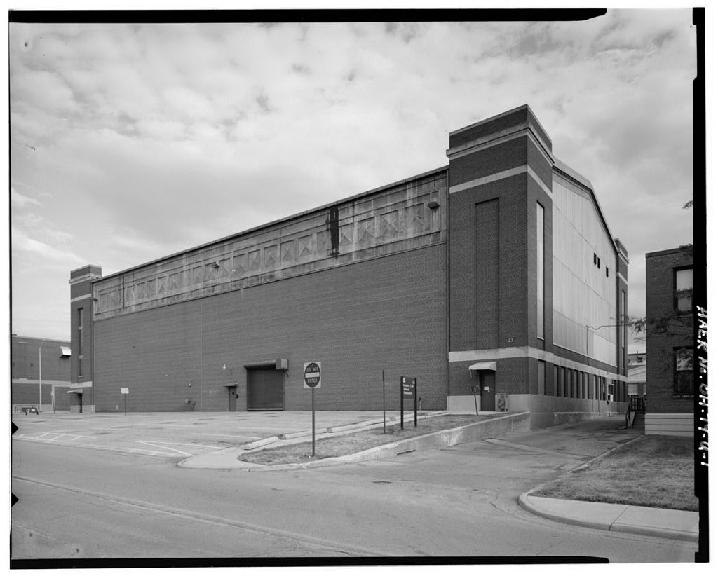
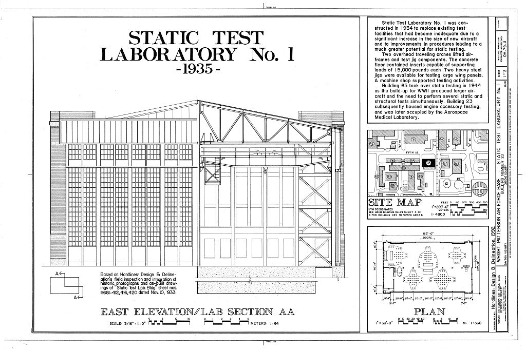
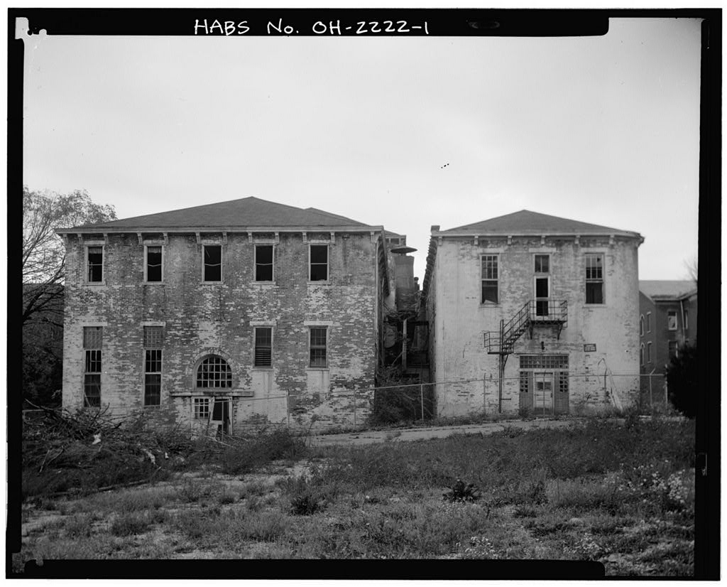
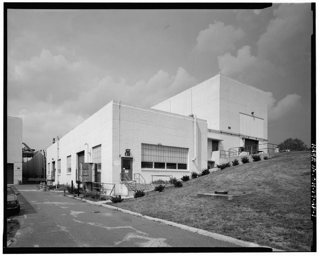
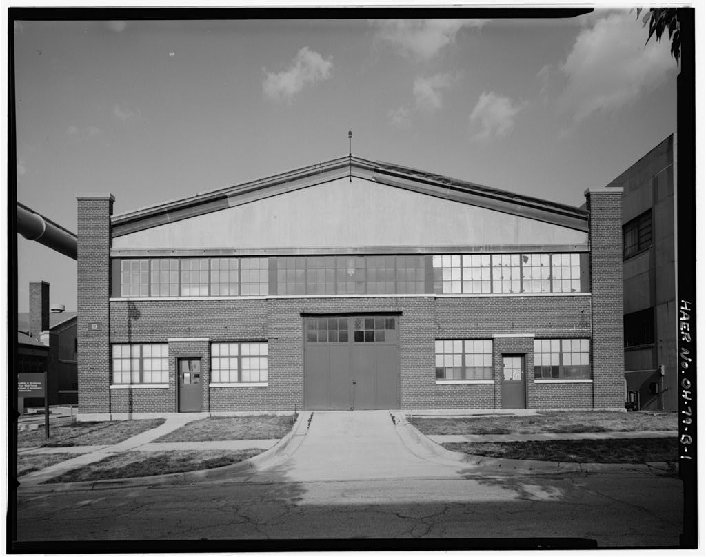
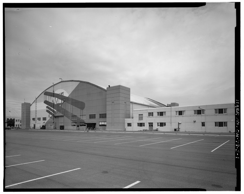
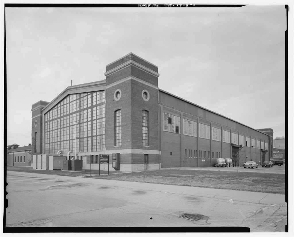
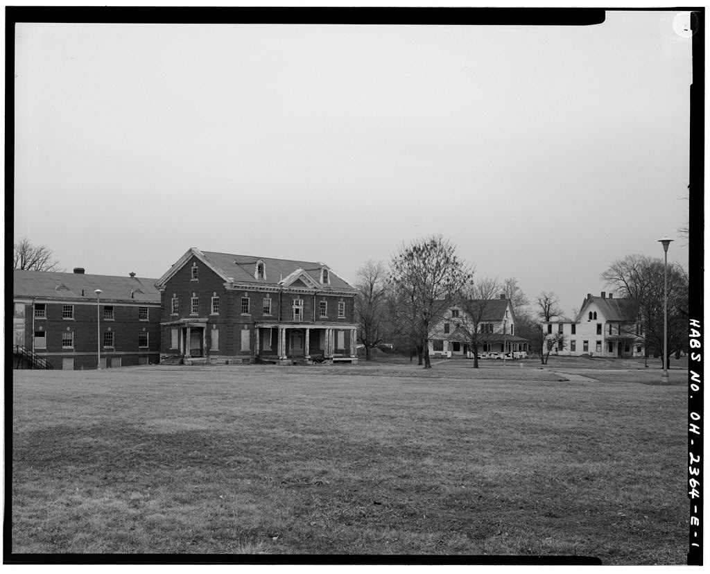
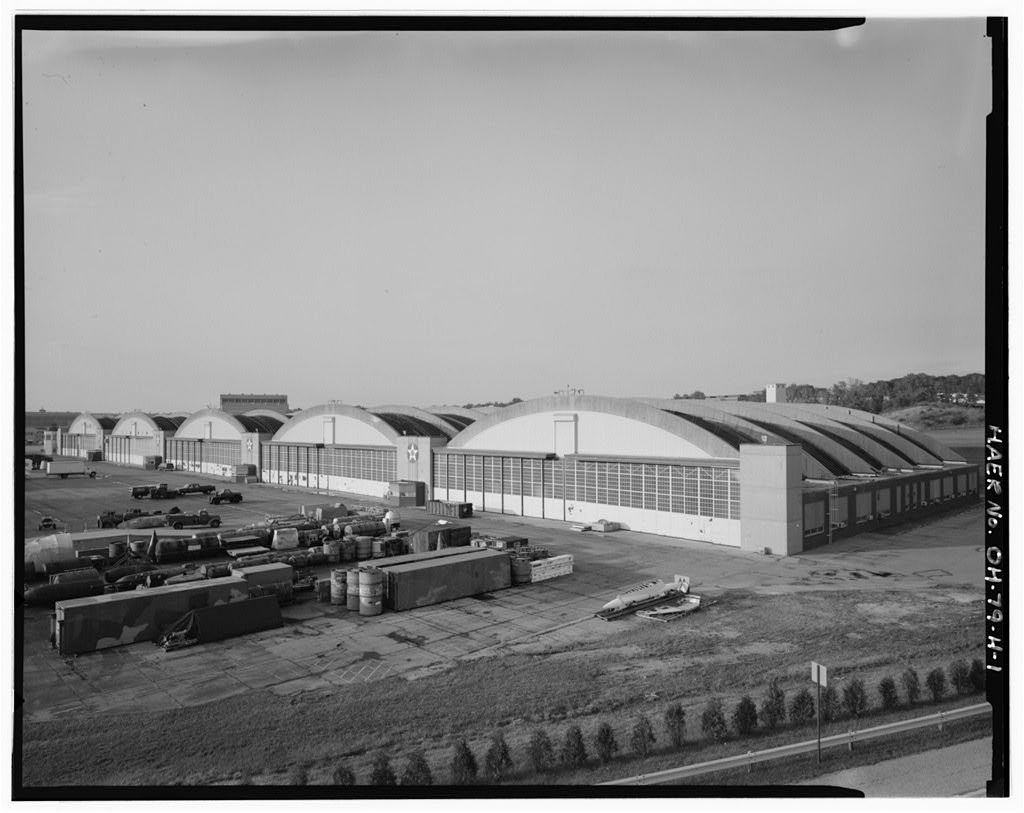
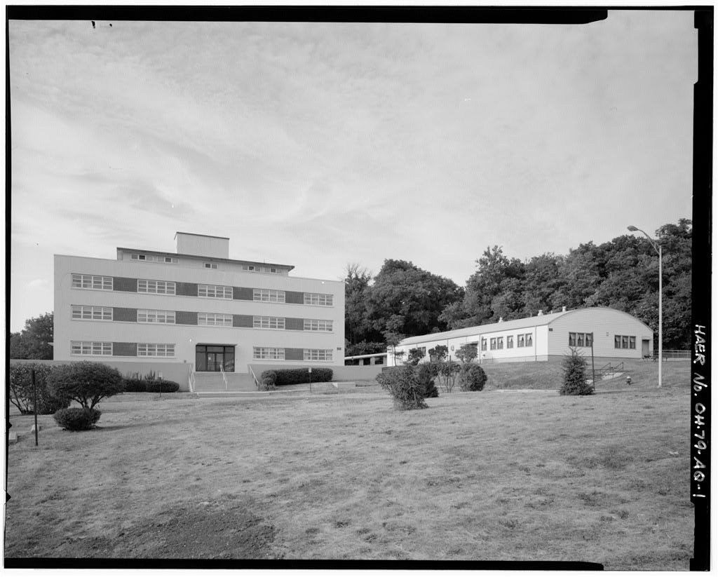
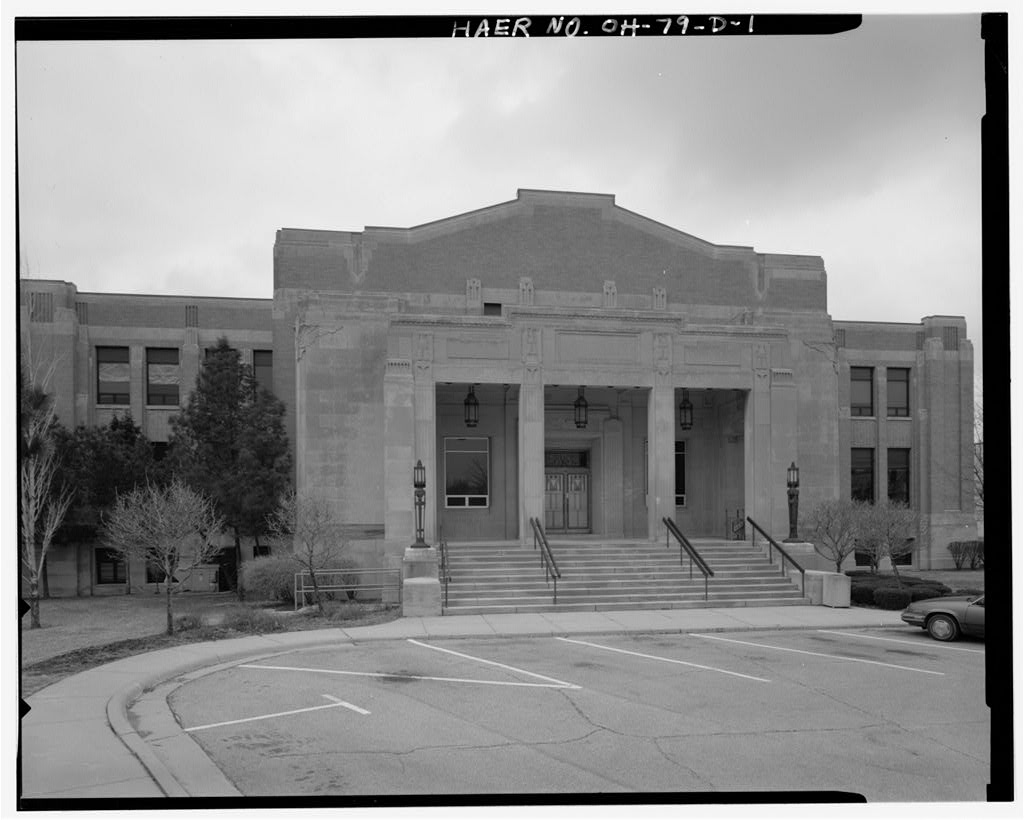
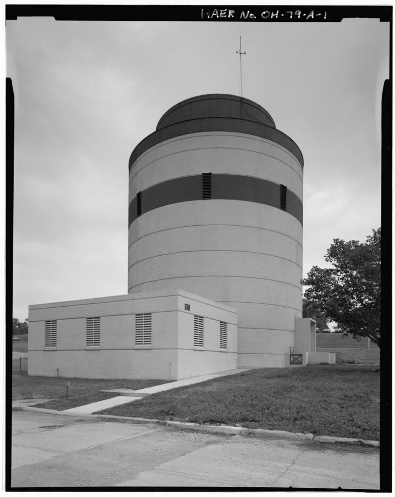
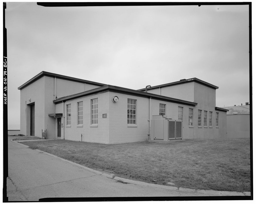
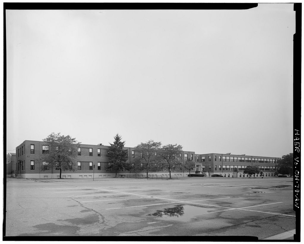
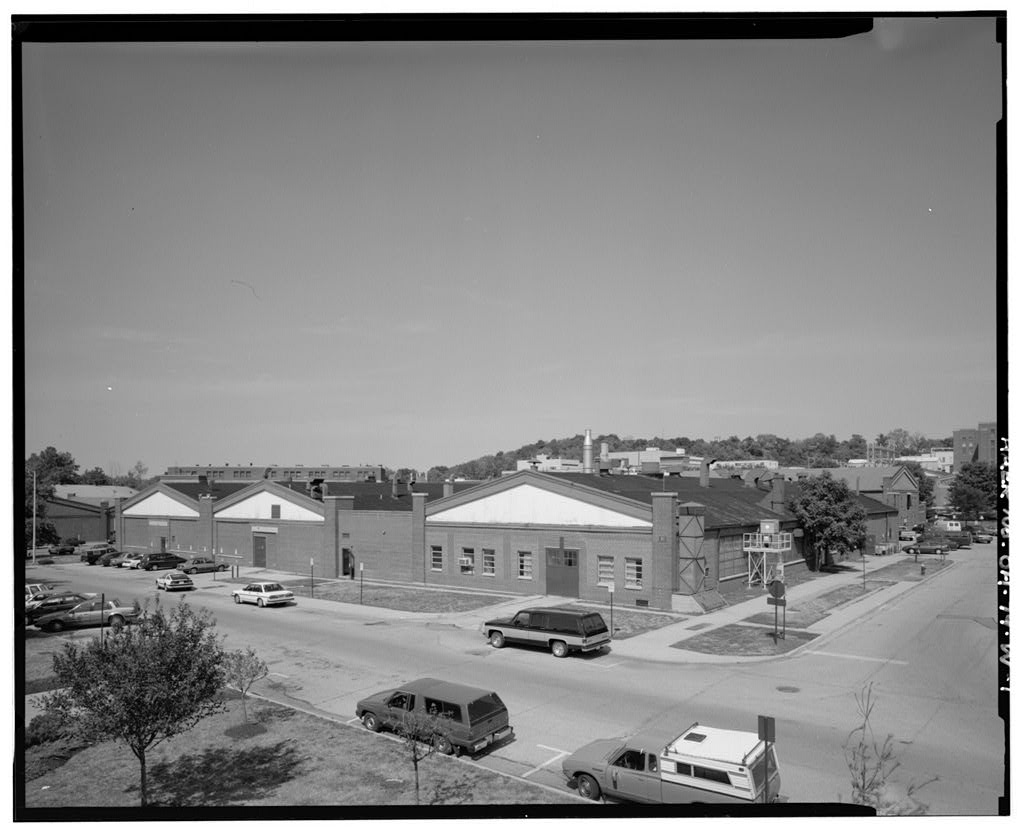
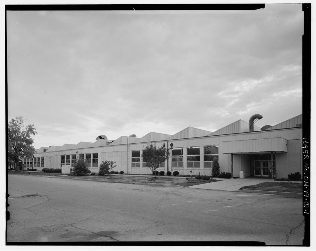
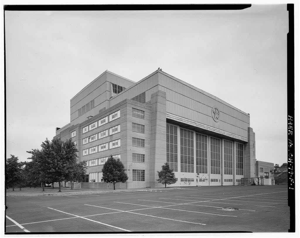
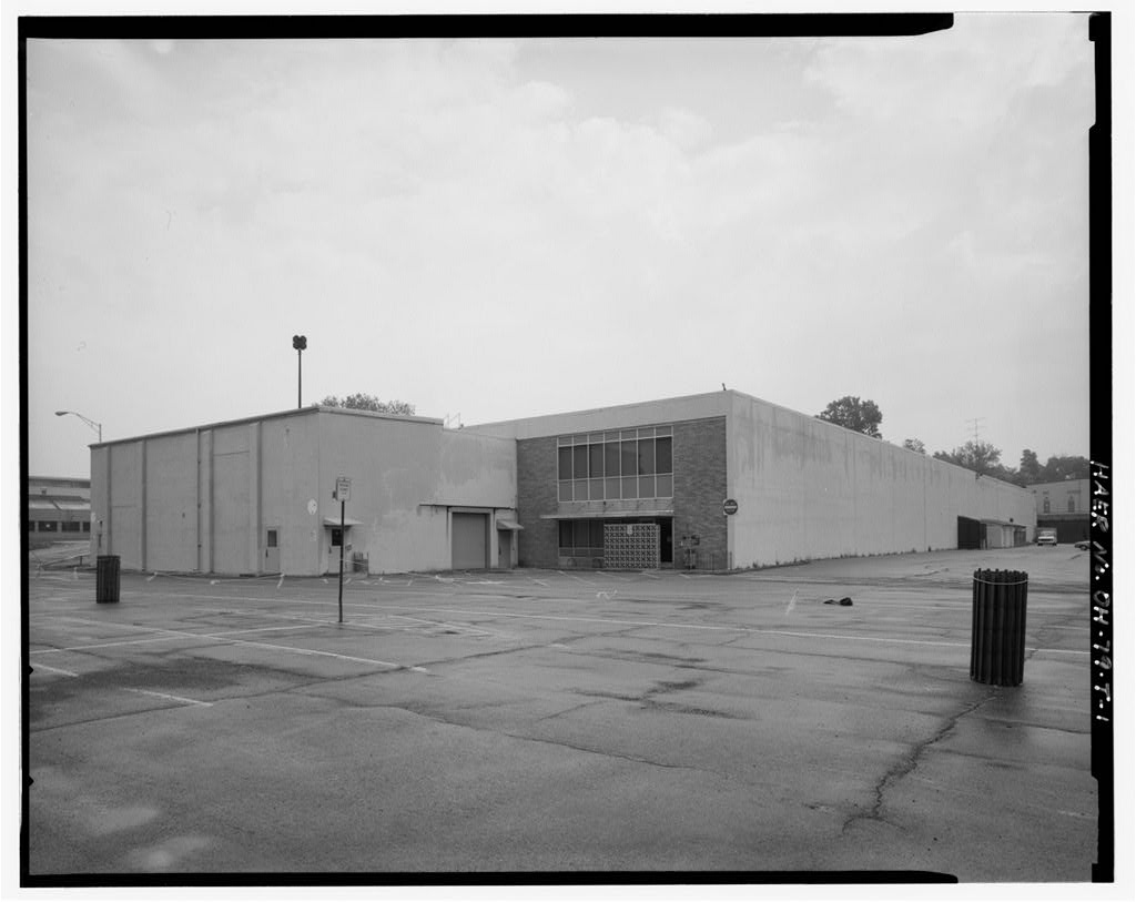
Wright-Patterson Air Force Base, Area B, Building 23, Static Test Laboratory No. 1, Southwest corner of Fifth & E Streets, Dayton
Wright-Patterson Air Force Base, Area B, Building 23, Static Test Laboratory No. 1, Southwest corner of Fifth & E Streets, Dayton, Montgomery County, OH. Surveyed as HAER OHIO,29-DAYT.V,1U-, with 1 photograph, 1 measured drawing and a 1,139-word written history.
From the record
“This building was the site of static structures tests on many World War II and earlier aircraft.”
Written record, HAER OHIO,29-DAYT.V,1U- survey. Machine-read text.
surveyed by the federal HAER program as HAER OHIO,29-DAYT.V,1U- · the record runs 1139 words · one of 121 surveyed structures published for this county.
1 photograph and 1 measured drawing from the federal survey record, Library of Congress.
Location
40 words
Source document
Quoted word for word from HAER OHIO,29-DAYT.V,1U-.
Not written, edited or summarised by this site.
Southwest corner of 5th and E Streets; Wright- Patterson Air Force Base, Area B, Dayton Vicinity, Greene County, Ohio. Date of Construction: Architect: Edgar R. Weaver, Chief of Static Test Laboratory. Construction Contractor: Works Progress Administration (WPA). Present Owner USAF.
Significance
82 words
The headings the report itself prints. Each one jumps to where it begins.
Source document
Quoted word for word from HAER OHIO,29-DAYT.V,1U-.
Not written, edited or summarised by this site.
This building was the site of static structures tests on many World War II and earlier aircraft. It exhibits architecture typical of the early period of construction at Wright Field. Project History This report is part of the overall Wright- Patterson Air Force Base, Area B documentation project conducted by HAER See overview report, HAER No. OH-79, for a complete description of the project. WRIGHT-PATTERSON AIR FORCE BASE, AREA B, BUILDING 23,
Static Test Laboratory
No. 1 HAER No. OH-79-U (Page 2)
DESCRIPTION
929 words
The headings the report itself prints. Each one jumps to where it begins.
Source document
Quoted word for word from HAER OHIO,29-DAYT.V,1U-.
Not written, edited or summarised by this site.
Building 2 3 is a six-course, American bond brick building with a copper entablature, typical of Wright Field. It measures x with a center roof height of The south, wall is constructed with extra brick and tile to deaden noise from the nearby propeller and power plant laboratories. Originally the north side of the building was the front, with a 10O' center- opening made up of eight sliding hangar-style doors on two tracks.
This opening was bricked in and replaced with conventional entrances after static test operations moved to the new Building 65 in Its large square corner towers are similar to those of Building 31, but the tower windows are not arched, the bull's eyes are not as ornate, and the decorative corner towers have only the two outer walls finished, resulting in a plainer, less visually dominant structure. The bull s eyes are now covered with green corrugated plastic. HISTORY: As military aircraft grew larger during the inter war period, some facilities at Wright Field also had to increase in size. One of these was the static test facility which had to be capacious enough to accommodate the largest military aircraft.
At ^fc the opening of Wright Field in static testing was performed ^^ in a portion of Building 31, the aircraft assembly hangar. Within a few years this space became terribly inadequate, both because airplanes quickly increased in size and because Wright Field engineers had greatly improved the procedures and therefore the experimental potential of static testing. This required a concomitant improvement in the size of the testing facility, so Building 23 was constructed in as a Works Progress Administration project and occupied in December of that year. One design flaw in this building was the use of a magnesium- fluro-silicate hardener on the concrete floors. This caused respiratory ailments and skin conditions among occupants of the building within ten weeks.
The problem was solved foy painting the floors. As originally used, the test floor was divided into two halves, each approximately 50' x . Two overhead travelling cranes of 5 and 15 ton capacity serviced the entire building, lifting airframes and test jig components. The 6" thick concrete floor contained inserts which could support loads of pounds each. Test structures could also be suspended from the crane and the flat bridge roof trusses, each of which could support a 50, G0O- pound concentrated load. Two heavy steel jigs were available to test large wing panels. Each could withstand a foot-pound moment and a pound shear. A machine shop was also set up to support the testing activities and perform minor repairs on airframes and parts. WRIGHT-PATTERSON AIR FORCE BASE, AREA B, BUILDING 23,
Static Test Laboratory
No. 1 HAER No. OH-79-U (Page 3) During Building decade as the static test laboratory, one of the most important projects developed cushion loading pads and tension loading pads. This research was performed on the a trainer aircraft that was the precursor of the advanced trainer AT- 6 Texan, in which nearly all American pilots of World War II passed their flight training. Loading pads are sponge rubber pads that are attached to the test structure (typically a wing) with epoxy. Cushion loading pads are attached to the top of the wing and transmit a compression load from a beam above the wing without damage to the wing's skin. Tension loading pads are attached to the bottom of the wing and loaded via hydraulic jacks.
Rather than always loading aircraft with dead weight, engineers had the alternative of applying discrete forces at specific points to obtain more exact simulations of flight conditions. Building 23 became inadequate when the military buildup for World War II produced both larger aircraft and the need to perform several static and structural tests simultaneously. The enormous Building 65 took over these functions in November and Building 2 3 began to host a new variety of experiments, including ^B engine accessory tests. With square feet of space, two large ^* cranes, and a 440-volt electrical system able to carry a horsepower drive system, this facility was perfectly suited for the testing of ignition, control, and other associated systems and components.
In the late the Aerospace Medical Laboratory installed medical science equipment in a portion of the building. In July the Medical Laboratory set up two ejection towers. One ejected subjects 35' downward into a curve of radius while the other ejected subjects upward at per second. The vertical accelerator, installed in July studied buffeting, vibration, and impact on objects of up to 4 00 pounds accelerated repeatedly to three times the force of gravity in a vertical distance of At the same time, the Medical Laboratory first used equilibrium chairs to study the mechanical and physiological effects of small amplitude vibrations in all three axes of space. Two years later, a 46' deceleration tower was introduced to test human subjects.
It had an experimental capability of imposing up to Building 2 3 hosted a variety of other facilities before becoming part of the Avionics Laboratory in One of the most interesting was the dynamic analyzer capsule of the 19 Constructed from pieces of a Snark missile, it used a system of six hydraulic rams to simulate the dynamic vibrations of high-altitude aircraft and was dubbed the "Rock and Roll." It was used to test and perfect photographic equipment for reconnaissance aircraft WRIGHT-PATTERSON AIR FORCE BASE, AREA B, BUILDING 23, STATIC TEST LABORATORY No. 1 HAER No. 0H-79-U (Page 4) without expensive in-flight testing. For bibliography, see Wright-Patterson Air Force Base overview report (HAER No. OH-79).
The original filed report, and the sheets the survey produced. Those published here appear above.
Also surveyed in Dayton
24 of 107 records shown
The federal surveyors worked through Dayton building by building. These are the other structures
they measured and filed a report on, longest report first.
 Block
Block