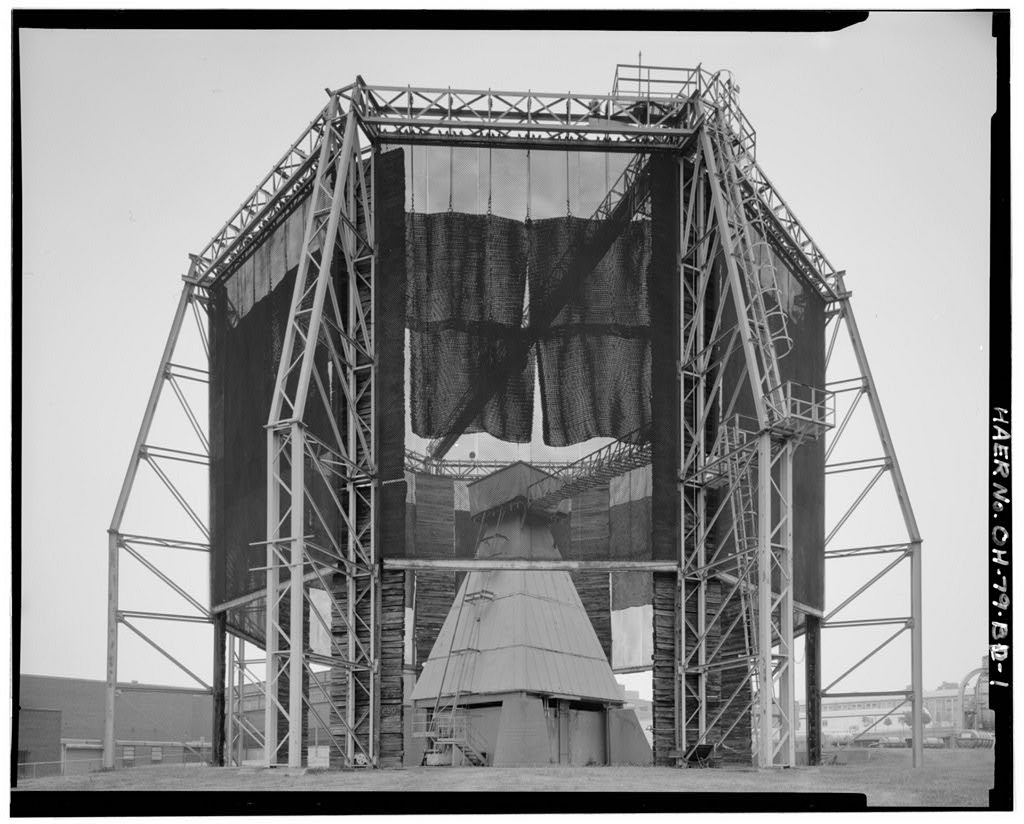
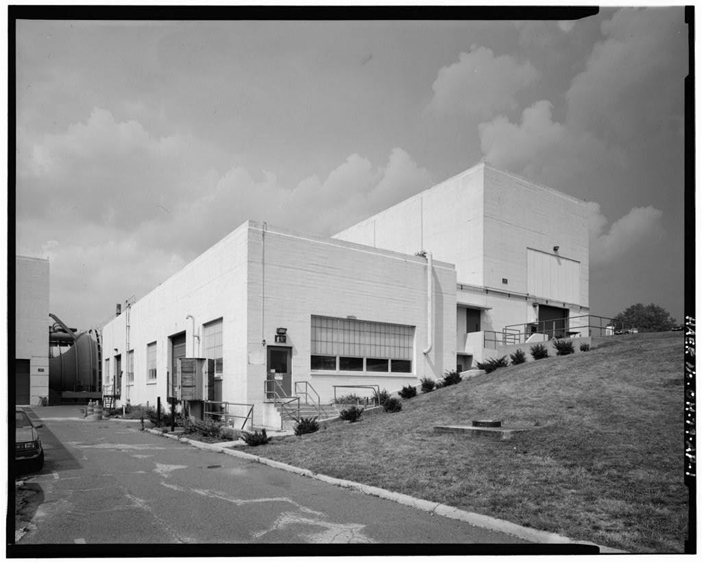
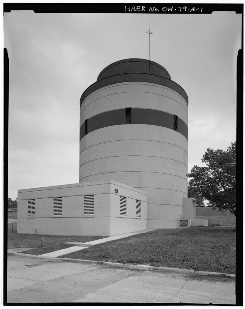
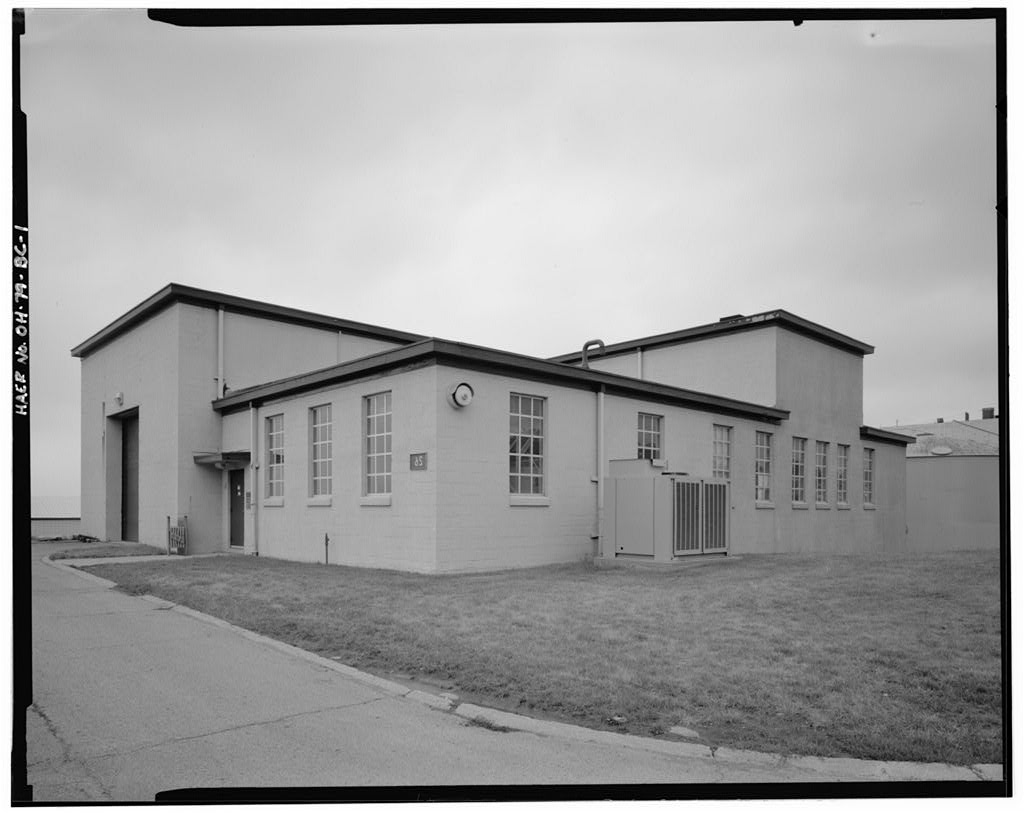
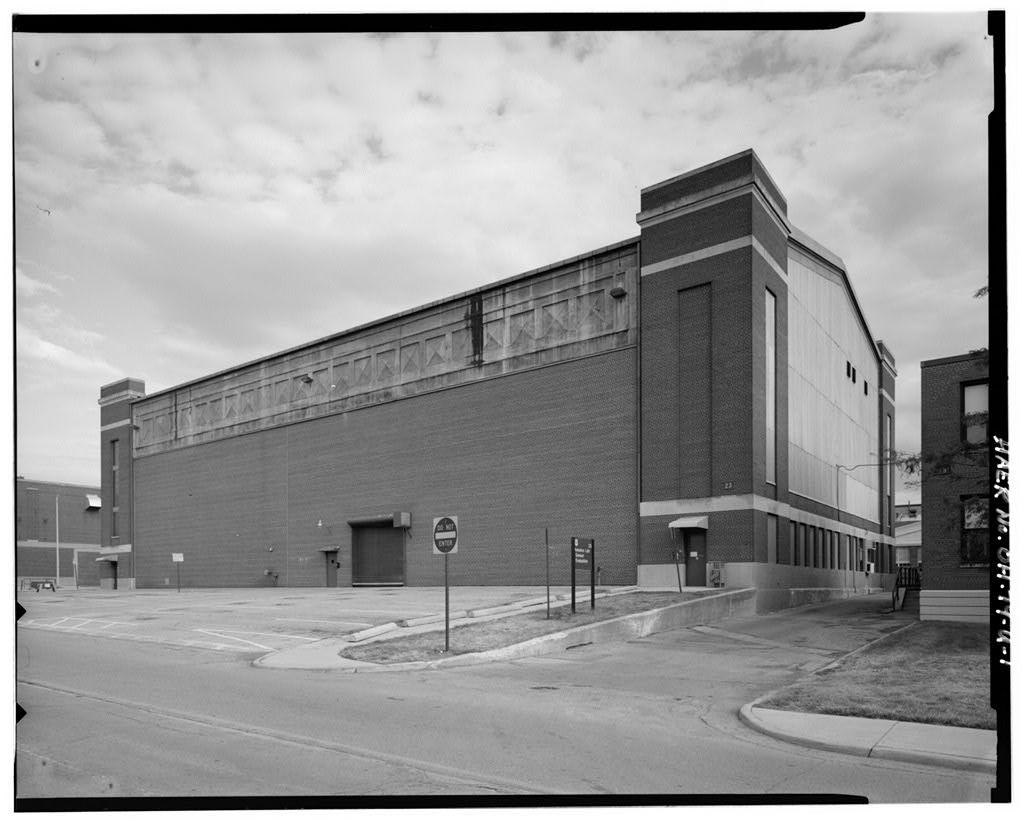
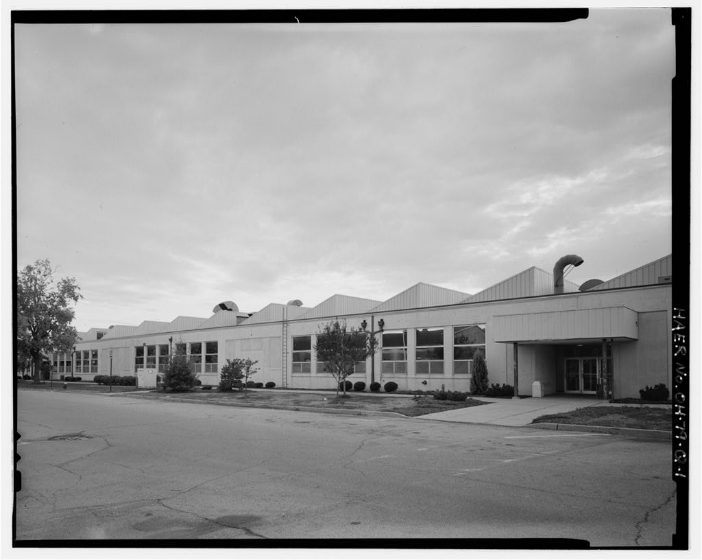
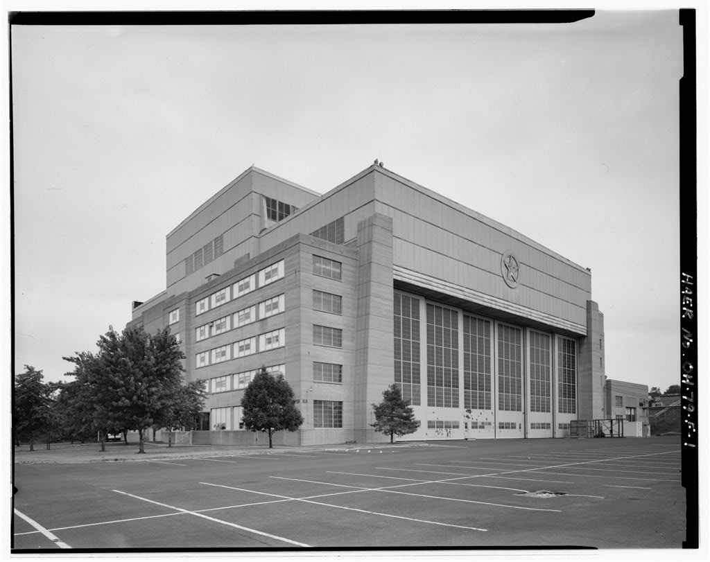
At the center of the rotor test site is a 50'-tall structural steel tower, covered with sheet steel. The tower has a 3 0-foot-square base and measures 61 across at the top. The concrete control room is located directly under the tower structure, and from here a large variable speed drive connects with a direct- driven vertical output shaft which turns the rotor blades. An elevator carries personnel to a removable work platform at the top of the tower. A safety enclosure with a diameter of 10 0' surrounds the tower and extends 25* above and below the plane of rotation. It consists of heavy wire mesh which hangs between eight structural steel vertical trusses. The removable work platform and a one-ton monorail crane extend across the top of the tower from the enclosure.
HISTORY: The Rotor Test Stand was built in to test helicopter blades of up to in diameter. It has a ground clearance of 50' to eliminate the ground-turbulence which arises when the blades are too low. The equipment has a maximum power of horsepower and can operate at speeds ranging from 150 to 600 revolutions per minute. The shaft is strong enough to resist thrusts of pounds and side loads of pounds, while the tower itself can sustain side loads of up to pounds. Instruments in the control room measure speed, power, thrust, and the side load imposed on the output shaft, and also track the rotor blades individually. To the east of the present rotor tower is a concrete pad which once supported an older rotor tower.
This tower was originally installed inside Building 2 0A, the propeller test acoustical enclosure, near the end of World War II, but was moved outside around to make room for propeller test rig Number 4, The test equipment consisted of two 500-horsepower, variable-speed, electric motors driving through a gear box into one common vertical shaft. Test articles of up to in diameter were attached to the shaft about 10' above the ground and rotated between 185 and 790 revolutions per minute. Instruments could measure the speed, power, and thrust imposed on the output shaft. The shaft could sustain thrusts up to pounds, and the tower could support instantaneous side loads up to pounds.
A 40'-high safety enclosure of structural steel and heavy wire mesh surrounded this tower at a diameter of Staff at the Propeller Lab relate that the mesh is hand-woven using elevator cables from the Empire State Building in New York. Unlike the larger tower, the drive equipment could be removed so that tie-down tests could be conducted on L complete helicopters. However, in all tests at this facility, the proximity of the rotor to the ground created turbulence patterns WRIGHT-PATTERSON AIR FORCE BASE, AREA B, BUILDING ROTOR TEST STAND HAER No. OH-79-BD (Page 3) that hampered attempts to effectively duplicate in-flight situations. Farther to the east is a gyroscopic propeller test stand (Building , which was constructed in and used for approximately fifteen years.
This was designed to test propellers under a variety of vibratory stress conditions. Test propellers were mounted inside a steel drum 19V in diameter by 3%f thick, which is evacuated to a simulated altitude of over feet. The propeller horsepower required is reduced by this vacuum so that propellers up to 20f in diameter, capable of absorbing up to horsepower, can be spun with a 60-horsepower electric motor. Superimposed on the normal rotation of the propeller is the rotation of the entire steel drum containing the test unit at speeds of up to 25 revolutions per minute. The gyroscopic action set up by this dual rotation produces vibratory stresses similar to those caused in flight by air flowing through the propeller at abnormal angles.
Propeller stresses induced by this rig simulate even the most severe flight conditions. Despite the capabilities of this unique device, it has not been used in nearly twenty years. For bibliography, see Wright-Patterson Air Force Base overview report (HAER No. OH-7 9). a
 Block
Block